sensor LEXUS LS430 2003 Factory Repair Manual
[x] Cancel search | Manufacturer: LEXUS, Model Year: 2003, Model line: LS430, Model: LEXUS LS430 2003Pages: 4500, PDF Size: 87.45 MB
Page 2871 of 4500
relay valve and locks the torque converter clutch.
If the ECM detects no lock-up after lock-up has been requested or if it detects lock-up when it is not requested,
the ECM interprets this as a fault in the shift solenoid valve SLU or lock-up system performance.
The ECM will turn on the MIL and store the DTC.
Example:
When any of the following is met, the system judges it as a malfunction.
a. There is a difference in rotation between before and after torque converters even when the ECM
commands lock-up.
(Engine speed is at least 75 rpm greater than input turbine speed.)
b. There is no difference in rotation between before and after torque converters even when the ECM
commands lock-up off.
(The difference between engine speed and input turbine speed is less than 35 rpm.)
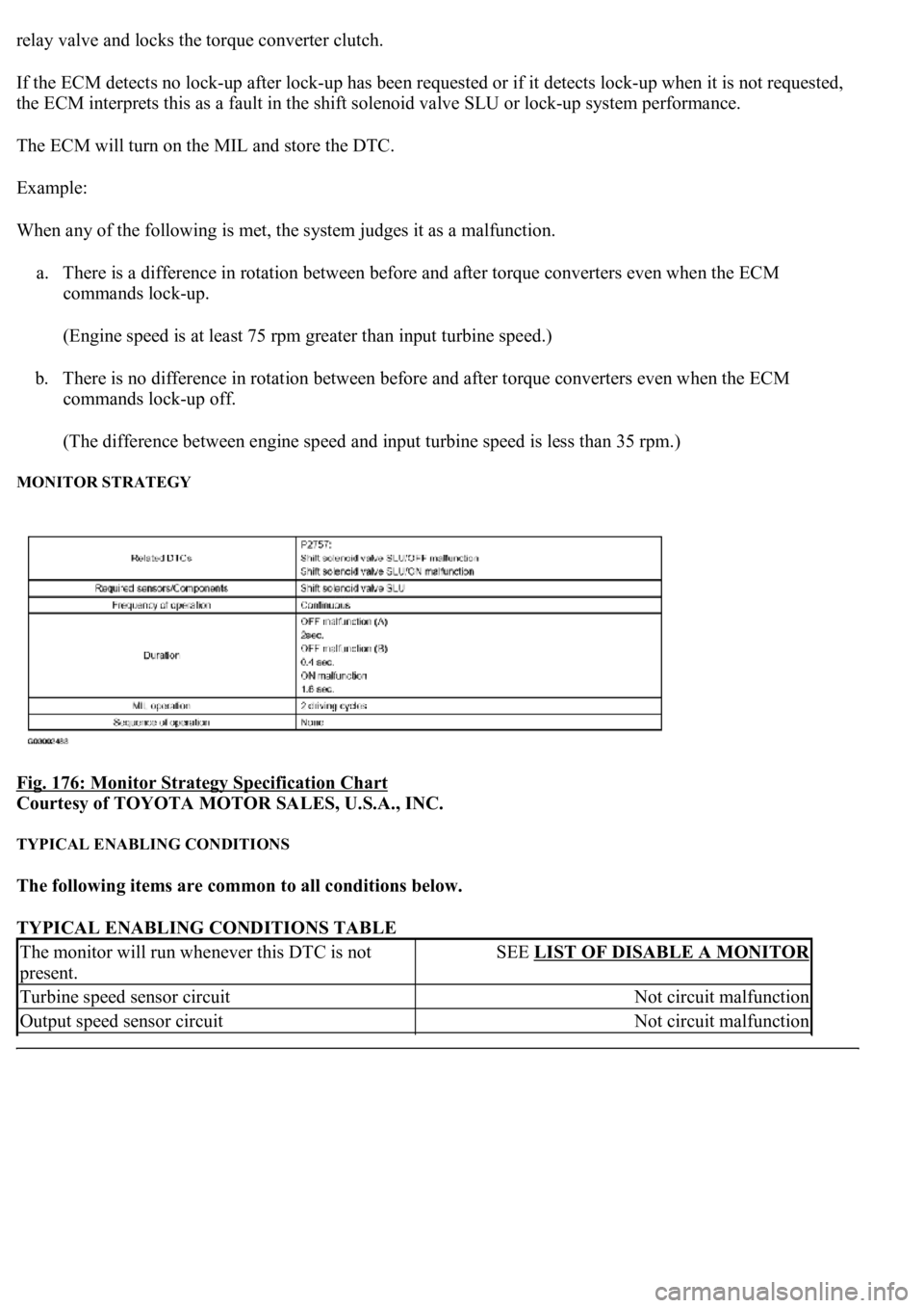
MONITOR STRATEGY
Fig. 176: Monitor Strategy Specification Chart
Courtesy of TOYOTA MOTOR SALES, U.S.A., INC.
TYPICAL ENABLING CONDITIONS
The following items are common to all conditions below.
TYPICAL ENABLING CONDITIONS TABLE
The monitor will run whenever this DTC is not
present.SEE LIST OF DISABLE A MONITOR
Turbine speed sensor circuitNot circuit malfunction
Output speed sensor circuitNot circuit malfunction
Page 2872 of 4500
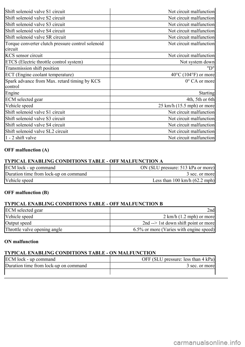
OFF malfunction (A)
TYPICAL ENABLING CONDITIONS TABLE - OFF MALFUNCTION A
OFF malfunction (B)
TYPICAL ENABLING CONDITIONS TABLE - OFF MALFUNCTION B
ON malfunction
TYPICAL ENABLING CONDITIONS TABLE - ON MALFUNCTION
Shift solenoid valve S1 circuitNot circuit malfunction
Shift solenoid valve S2 circuitNot circuit malfunction
Shift solenoid valve S3 circuitNot circuit malfunction
Shift solenoid valve S4 circuitNot circuit malfunction
Shift solenoid valve SR circuitNot circuit malfunction
Torque converter clutch pressure control solenoid
circuitNot circuit malfunction
KCS sensor circuitNot circuit malfunction
ETCS (Electric throttle control system)Not system down
Transmission shift position"D"
ECT (Engine coolant temperature)40°C (104°F) or more
Spark advance from Max. retard timing by KCS
control0° CA or more
EngineStarting
ECM selected gear4th, 5th or 6th
Vehicle speed25 km/h (15.5 mph) or more
Shift solenoid valve S1 circuitNot circuit malfunction
Shift solenoid valve S3 circuitNot circuit malfunction
Shift solenoid valve S4 circuitNot circuit malfunction
Shift solenoid valve SL2 circuitNot circuit malfunction
1 - 2 shift valveNot circuit malfunction
ECM lock - up commandON (SLU pressure: 513 kPa or more)
Duration time from lock-up on command3 sec. or more
Vehicle speedLess than 100 km/h (62.2 mph)
ECM selected gear2nd
Vehicle speed2 km/h (1.2 mph) or more
Output speed2nd --> 1st down shift point or more
Throttle valve opening angle6.5% or more (Varies with engine speed)
ECM lock - up commandOFF (SLU pressure: less than 4 kPa)
Duration time from lock-up on command3 sec. or more
Page 2873 of 4500

TYPICAL MALFUNCTION THRESHOLDS
Both of the following conditions are met: OFF malfunction (A) and (B)
OFF malfunction (A)
TYPICAL MALFUNCTION THRESHOLDS TABLE - OFF MALFUNCTION A
OFF malfunction (B)
TYPICAL MALFUNCTION THRESHOLDS TABLE - OFF MALFUNCTION B
ON malfunction
2 detections are necessary per driving cycle:
1st detection; temporary flag ON
2md detection; pending fault code ON
Vehicle speed must be under 10 km/h (6.2 mph) once before 2nd detection.
TYPICAL MALFUNCTION THRESHOLDS TABLE - ON MALFUNCTION
COMPONENT OPERATING RANGE
COMPONENT OPERATING RANGE TABLE
INSPECTION PROCEDURE
HINT:
Performing the ACTIVE TEST using the hand-held tester allows the relay, VSV, actuator and so on to operate
without parts removal. Performing the ACTIVE TEST as the first step of troubleshooting is one method to
shorten labor time.
It is possible to display the DATA LIST during the ACTIVE TEST.
Throttle valve opening angle9% or more
Vehicle speedLess than 60 km/h (37.3 mph)
Engine speed - Turbine speed (NE - NT)70 rpm or more
Engine speed - Turbine speed (NE - NT)Not 3.08 to 7.50
Engine speed - Turbine speed| (|NE - NT|)Less than 35 rpm
Speed sensor (NT)Input speed is equal to engine speed when lock-up
ON.
Page 2879 of 4500
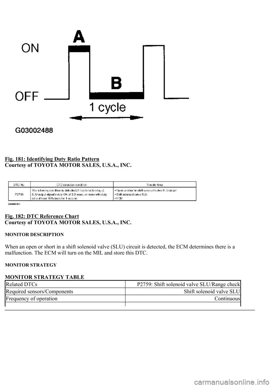
Fig. 181: Identifying Duty Ratio Pattern
Courtesy of TOYOTA MOTOR SALES, U.S.A., INC.
Fig. 182: DTC Reference Chart
Courtesy of TOYOTA MOTOR SALES, U.S.A., INC.
MONITOR DESCRIPTION
When an open or short in a shift solenoid valve (SLU) circuit is detected, the ECM determines there is a
malfunction. The ECM will turn on the MIL and store this DTC.
MONITOR STRATEGY
MONITOR STRATEGY TABLE
Related DTCsP2759: Shift solenoid valve SLU/Range check
Required sensors/ComponentsShift solenoid valve SLU
Frequency of operationContinuous
Page 2894 of 4500
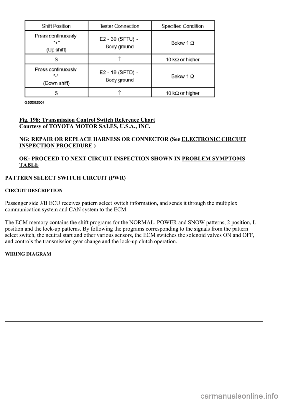
Fig. 198: Transmission Control Switch Reference Chart
Courtesy of TOYOTA MOTOR SALES, U.S.A., INC.
NG: REPAIR OR REPLACE HARNESS OR CONNECTOR (See ELECTRONIC CIRCUIT
INSPECTION PROCEDURE )
OK: PROCEED TO NEXT CIRCUIT INSPECTION SHOWN IN PROBLEM SYMPTOMS
TABLE
PATTERN SELECT SWITCH CIRCUIT (PWR)
CIRCUIT DESCRIPTION
Passenger side J/B ECU receives pattern select switch information, and sends it through the multiplex
communication system and CAN system to the ECM.
The ECM memory contains the shift programs for the NORMAL, POWER and SNOW patterns, 2 position, L
position and the loc
k-up patterns. By following the programs corresponding to the signals from the pattern
select switch, the neutral start and other various sensors, the ECM switches the solenoid valves ON and OFF,
and controls the transmission gear change and the lock-up clutch operation.
WIRING DIAGRAM
Page 2905 of 4500
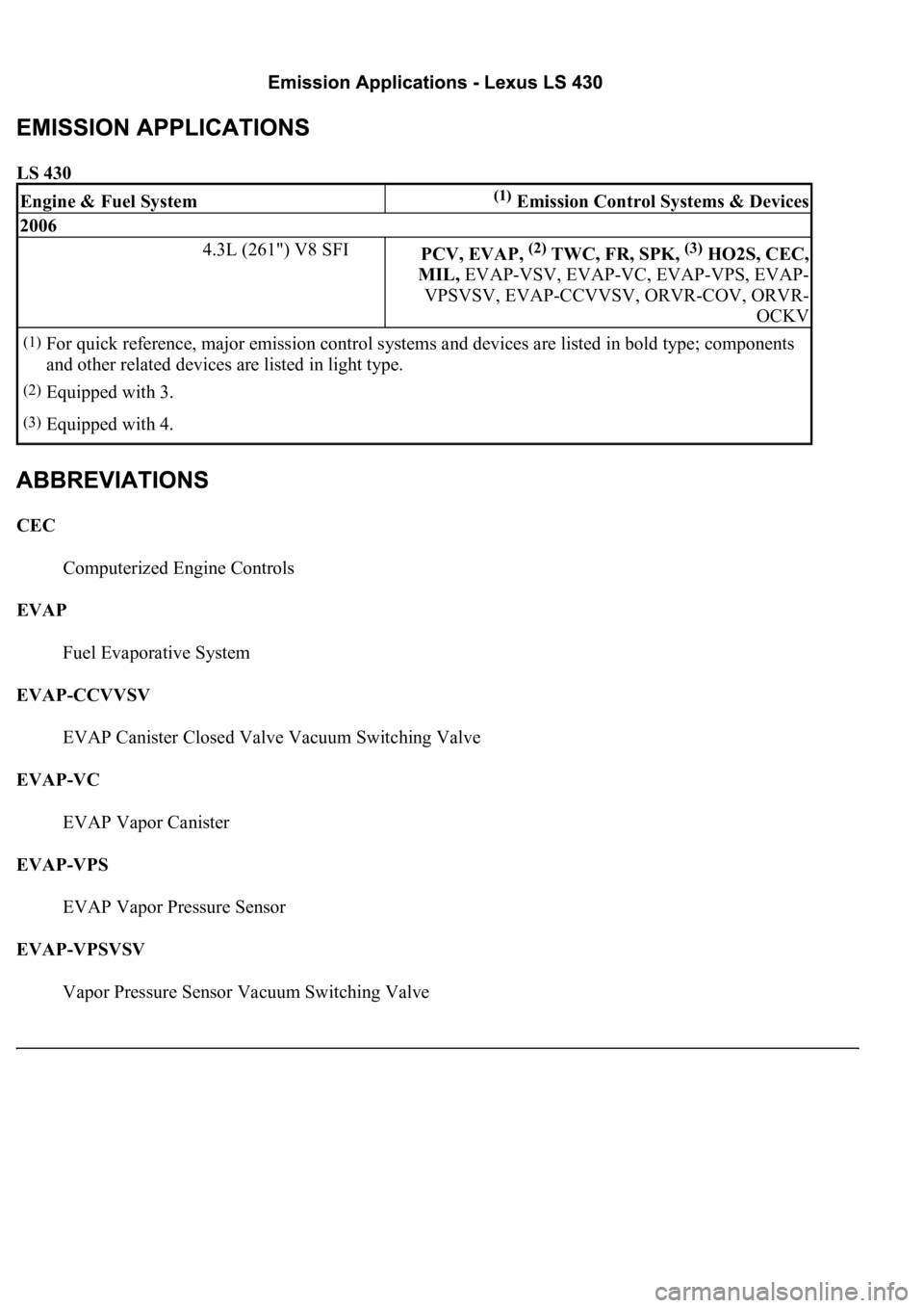
LS 430
CEC
Computerized Engine Controls
EVAP
Fuel Evaporative System
EVAP-CCVVSV
EVAP Canister Closed Valve Vacuum Switching Valve
EVAP-VC
EVAP Vapor Canister
EVAP-VPS
EVAP Vapor Pressure Sensor
EVAP-VPSVSV
Vapor Pressure Sensor Vacuum Switching Valve
Engine & Fuel System(1) Emission Control Systems & Devices
2006
4.3L (261") V8 SFIPCV, EVAP, (2) TWC, FR, SPK, (3) HO2S, CEC,
MIL, EVAP-VSV, EVAP-VC, EVAP-VPS, EVAP-
VPSVSV, EVAP-CCVVSV, ORVR-COV, ORVR-
OCKV
(1)For quick reference, major emission control systems and devices are listed in bold type; components
and other related devices are listed in light type.
(2)Equipped with 3.
(3)Equipped with 4.
Page 2906 of 4500
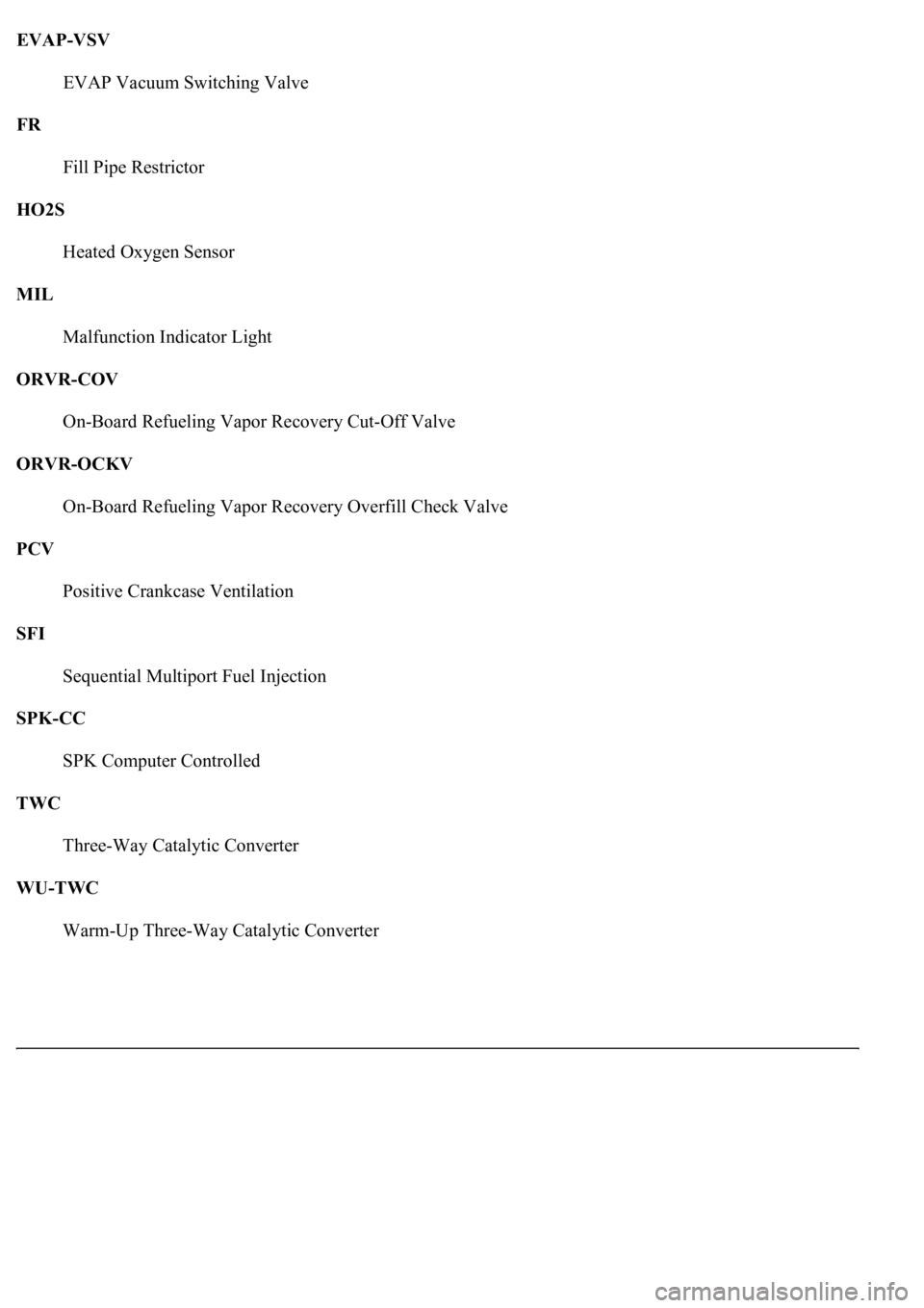
EVAP-VSV
EVAP Vacuum Switching Valve
FR
Fill Pipe Restrictor
HO2S
Heated Oxygen Sensor
MIL
Malfunction Indicator Light
ORVR-COV
On-Board Refueling Vapor Recovery Cut-Off Valve
ORVR-OCKV
On-Board Refueling Vapor Recovery Overfill Check Valve
PCV
Positive Crankcase Ventilation
SFI
Sequential Multiport Fuel Injection
SPK-CC
SPK Computer Controlled
TWC
Three-Way Catalytic Converter
WU-TWC
Warm-Up Three-Wa
y Catalytic Converter
Page 2912 of 4500
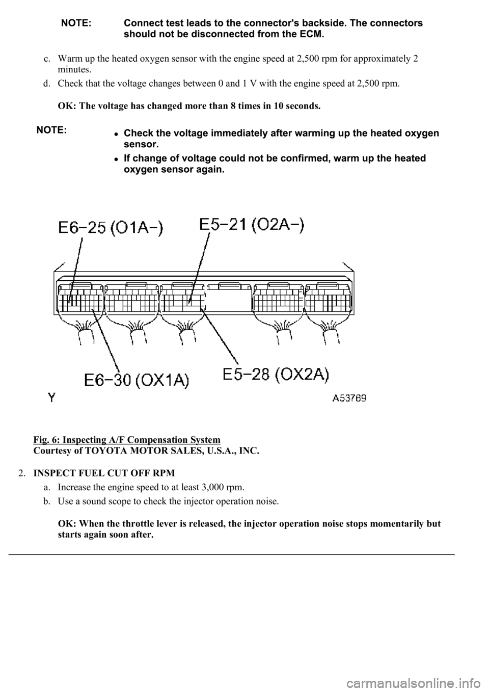
c. Warm up the heated oxygen sensor with the engine speed at 2,500 rpm for approximately 2
minutes.
d. Check that the voltage changes between 0 and 1 V with the engine speed at 2,500 rpm.
OK: The voltage has changed more than 8 times in 10 seconds.
Fig. 6: Inspecting A/F Compensation System
Courtesy of TOYOTA MOTOR SALES, U.S.A., INC.
2.INSPECT FUEL CUT OFF RPM
a. Increase the engine speed to at least 3,000 rpm.
b. Use a sound scope to check the injector operation noise.
OK: When the throttle lever is released, the injector operation noise stops momentarily but
starts again soon after.
Page 2914 of 4500
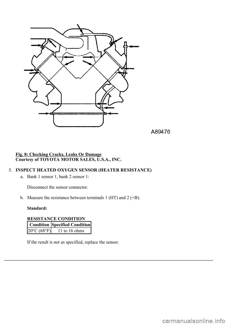
Fig. 8: Checking Cracks, Leaks Or Damage
Courtesy of TOYOTA MOTOR SALES, U.S.A., INC.
5.INSPECT HEATED OXYGEN SENSOR (HEATER RESISTANCE)
a. Bank 1 sensor 1, bank 2 sensor 1:
Disconnect the sensor connector.
b. Measure the resistance between terminals 1 (HT) and 2 (+B).
Standard:
RESISTANCE CONDITION
If the result is not as specified, replace the sensor.
ConditionSpecified Condition
20°C (68°F)11 to 16 ohms
Page 2915 of 4500
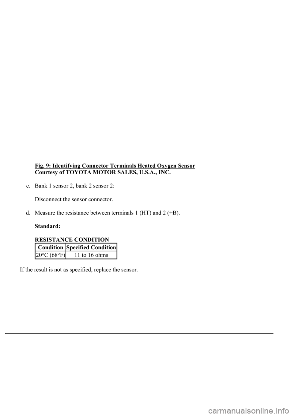
Fig. 9: Identifying Connector Terminals Heated Oxygen Sensor
Courtesy of TOYOTA MOTOR SALES, U.S.A., INC.
c. Bank 1 sensor 2, bank 2 sensor 2:
Disconnect the sensor connector.
d. Measure the resistance between terminals 1 (HT) and 2 (+B).
Standard:
RESISTANCE CONDITION
If the result is not as specified, replace the sensor.
ConditionSpecified Condition
20°C (68°F)11 to 16 ohms