LEXUS LS430 2003 Factory Repair Manual
LS430 2003
LEXUS
LEXUS
https://www.carmanualsonline.info/img/36/57050/w960_57050-0.png
LEXUS LS430 2003 Factory Repair Manual
Page 2964 of 4500
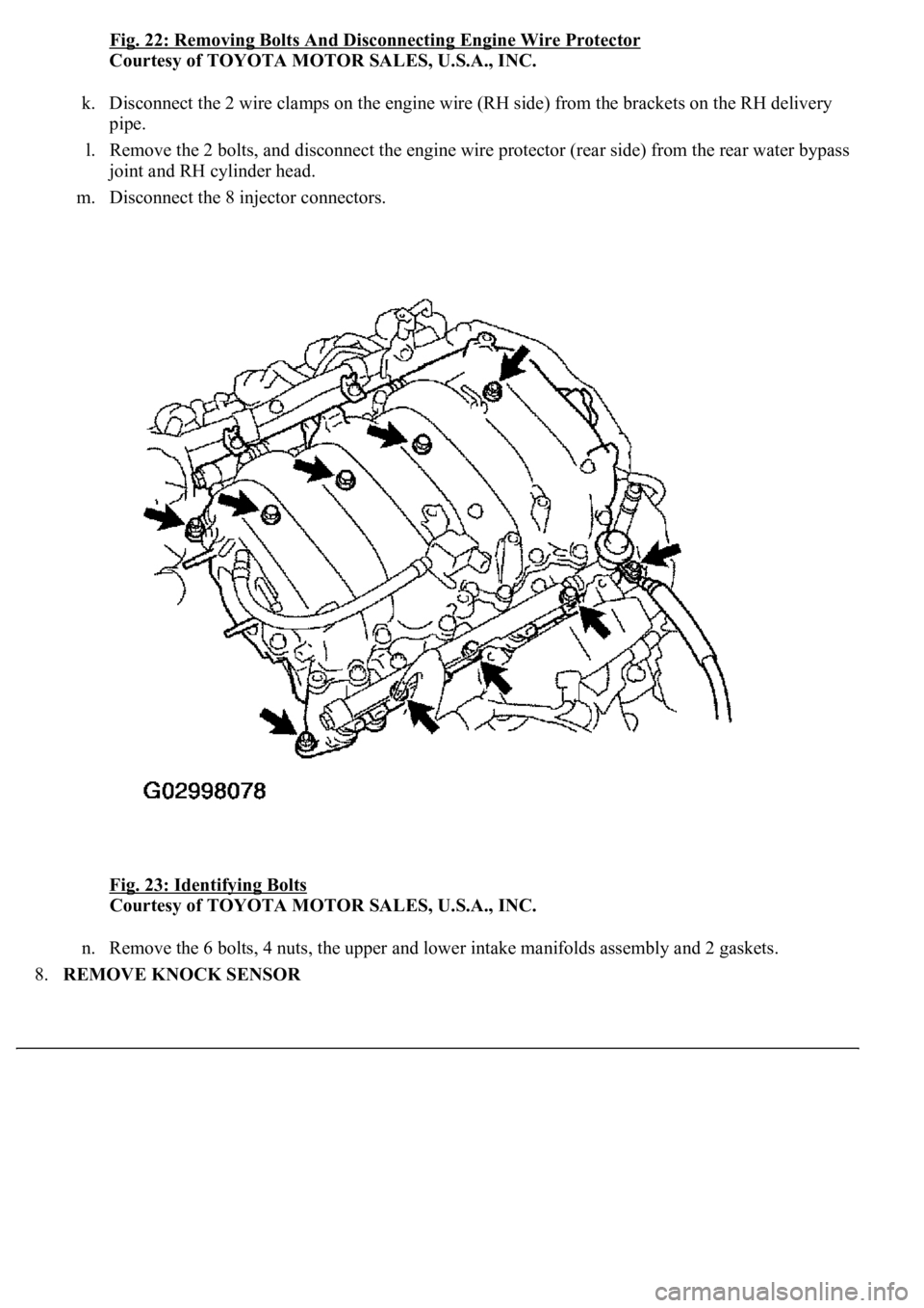
Fig. 22: Removing Bolts And Disconnecting Engine Wire Protector
Courtesy of TOYOTA MOTOR SALES, U.S.A., INC.
k. Disconnect the 2 wire clamps on the engine wire (RH side) from the brackets on the RH delivery
pipe.
l. Remove the 2 bolts, and disconnect the engine wire protector (rear side) from the rear water bypass
joint and RH cylinder head.
m. Disconnect the 8 injector connectors.
Fig. 23: Identifying Bolts
Courtesy of TOYOTA MOTOR SALES, U.S.A., INC.
n. Remove the 6 bolts, 4 nuts, the upper and lower intake manifolds assembly and 2 gaskets.
8.REMOVE KNOCK SENSOR
Page 2965 of 4500
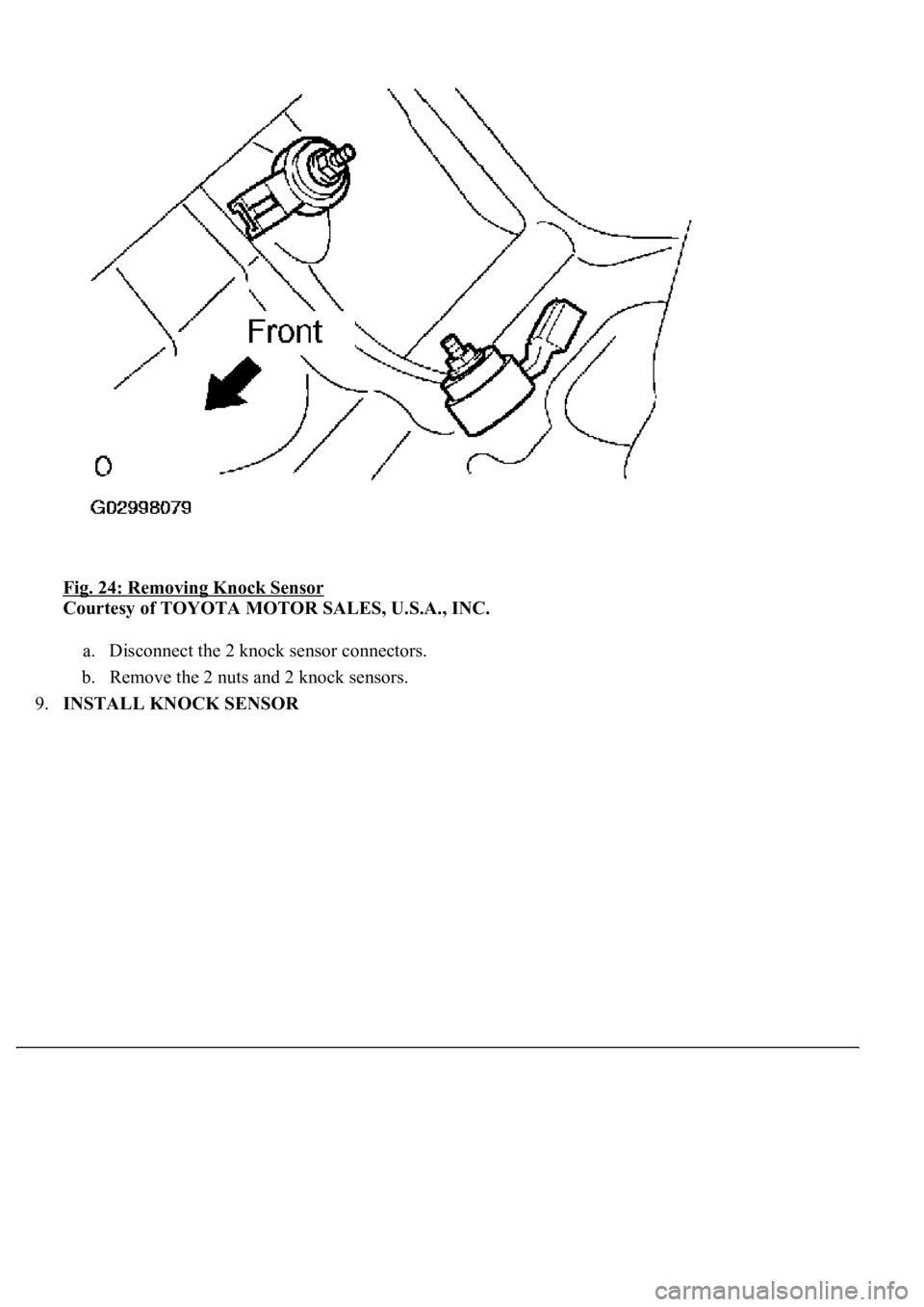
Fig. 24: Removing Knock Sensor
Courtesy of TOYOTA MOTOR SALES, U.S.A., INC.
a. Disconnect the 2 knock sensor connectors.
b. Remove the 2 nuts and 2 knock sensors.
9.INSTALL KNOCK SENSOR
Page 2966 of 4500
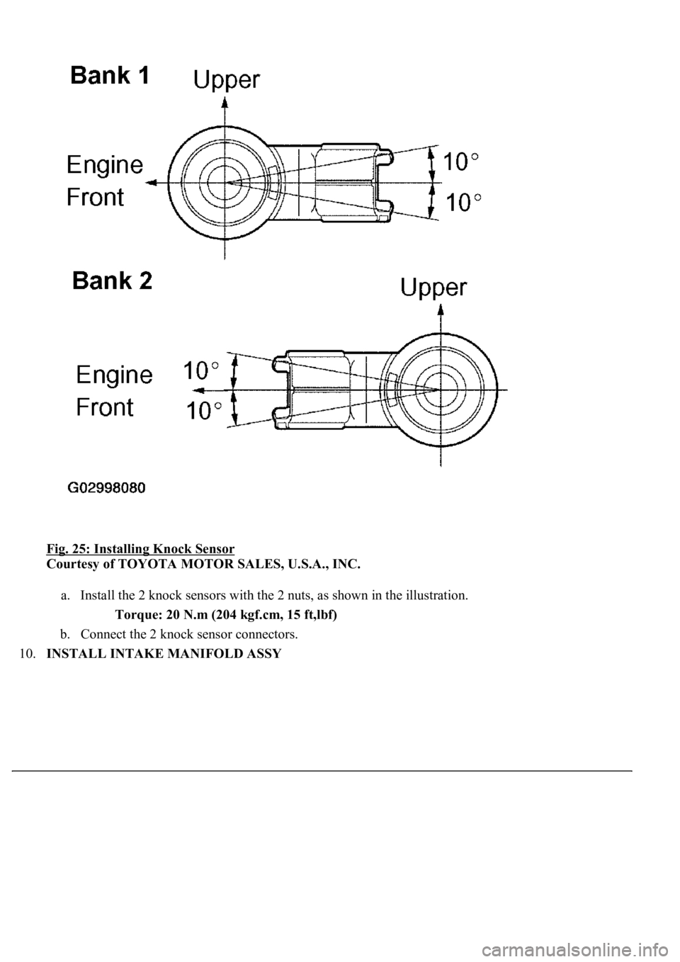
Fig. 25: Installing Knock Sensor
Courtesy of TOYOTA MOTOR SALES, U.S.A., INC.
a. Install the 2 knock sensors with the 2 nuts, as shown in the illustration.
Torque: 20 N.m (204 kgf.cm, 15 ft,lbf)
b. Connect the 2 knock sensor connectors.
10.INSTALL INTAKE MANIFOLD ASSY
Page 2983 of 4500
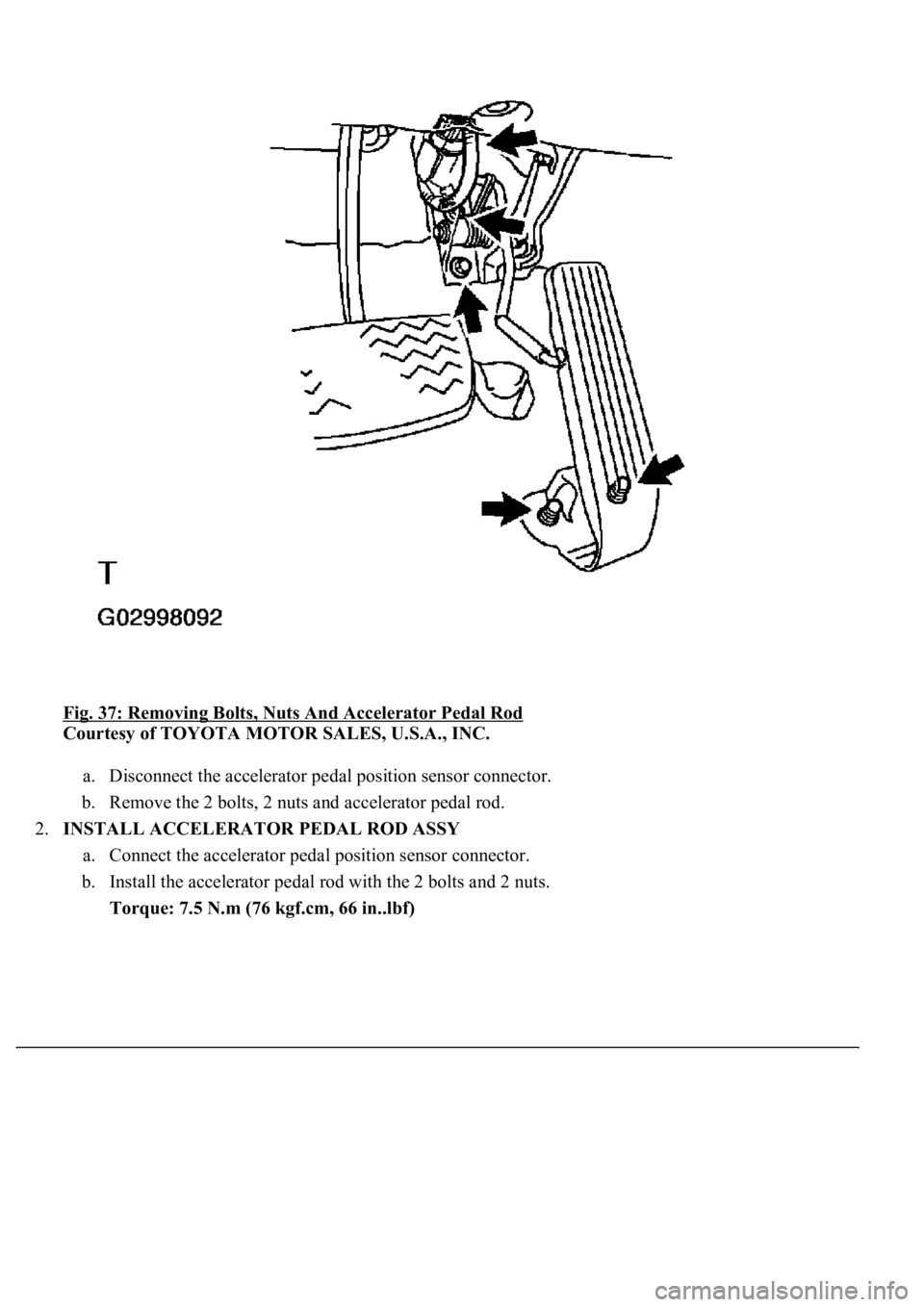
<0029004c004a001100030016001a001d000300350048005000520059004c0051004a000300250052004f00570056000f00030031005800570056000300240051004700030024004600460048004f0048005500440057005200550003003300480047004400
4f0003003500520047[
Courtesy of TOYOTA MOTOR SALES, U.S.A., INC.
a. Disconnect the accelerator pedal position sensor connector.
b. Remove the 2 bolts, 2 nuts and accelerator pedal rod.
2.INSTALL ACCELERATOR PEDAL ROD ASSY
a. Connect the accelerator pedal position sensor connector.
b. Install the accelerator pedal rod with the 2 bolts and 2 nuts.
Torque: 7.5 N.m (76 kgf.cm, 66 in..lbf)
Page 2990 of 4500
5. Adjust the hood lock.
1. w/ Pre-collision safety system:
Disconnect the cable from the battery negative (-) terminal.
2. w/ Pre-collision safety system:
Disconnect the connector.
3. w/ Pre-collision safety system:
Remove the 3 bolts and millimeter wave radar sensor.
Fig. 6: Removing Bolts And Millimeter Wave Radar Sensor
Courtesy of TOYOTA MOTOR SALES, U.S.A., INC.
4. Remove the cap (see OVERHAUL
).
5. Loosen the 2 bolts and nut.
6. Ad
just the hood lock position so that the striker can enter it smoothly.
Page 2991 of 4500
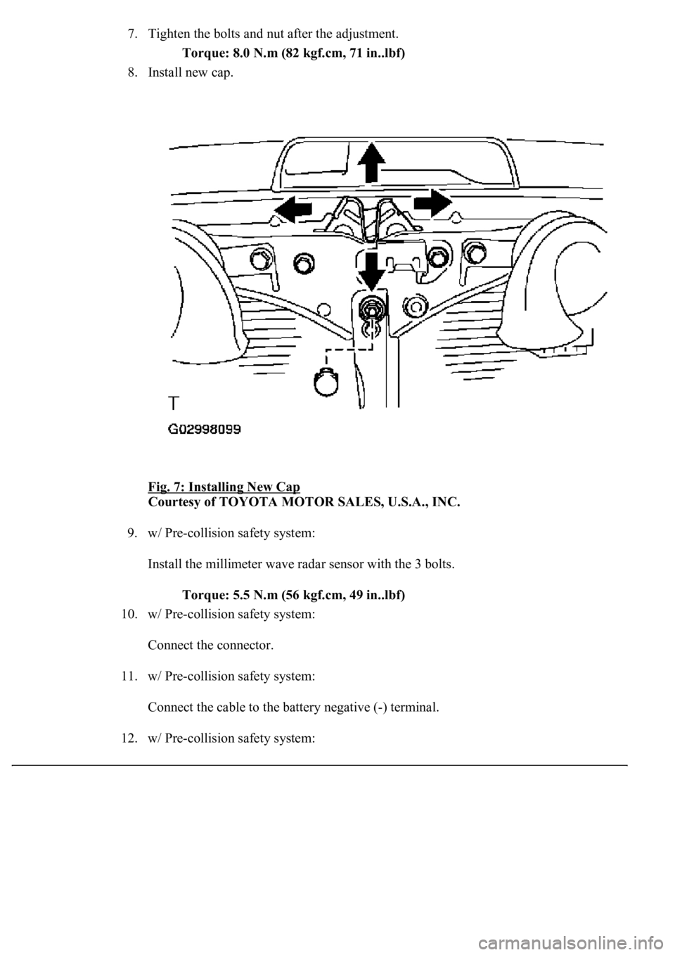
7. Tighten the bolts and nut after the adjustment.
Torque: 8.0 N.m (82 kgf.cm, 71 in..lbf)
8. Install new cap.
Fig. 7: Installing New Cap
Courtesy of TOYOTA MOTOR SALES, U.S.A., INC.
9. w/ Pre-collision safety system:
Install the millimeter wave radar sensor with the 3 bolts.
Torque: 5.5 N.m (56 kgf.cm, 49 in..lbf)
10. w/ Pre-collision safety system:
Connect the connector.
11. w/ Pre-collision safety system:
<002600520051005100480046005700030057004b00480003004600440045004f004800030057005200030057004b00480003004500440057005700480055005c000300510048004a00440057004c005900480003000b0010000c0003005700480055005000
4c00510044004f00110003[
12. w/ Pre-collision safet
y system:
Page 2992 of 4500
Preform the initialization (see INITIALIZATION).
13. w/ Pre-collision safety system:
Inspect the SRS warning lamp (see DIAGNOSIS SYSTEM
).
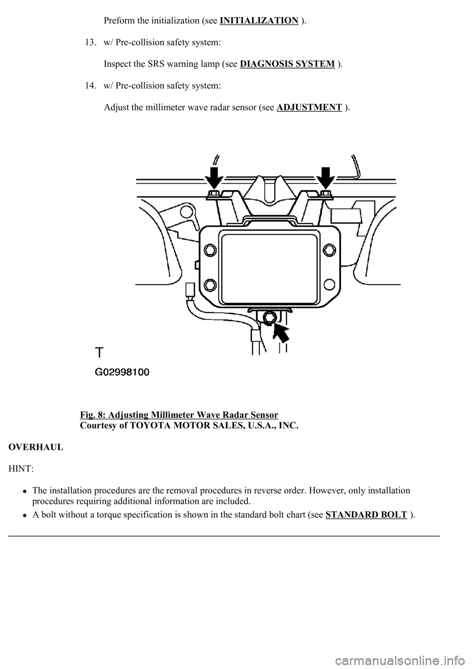
14. w/ Pre-collision safety system:
Adjust the millimeter wave radar sensor (see ADJUSTMENT
).
Fig. 8: Adjusting Millimeter Wave Radar Sensor
Courtesy of TOYOTA MOTOR SALES, U.S.A., INC.
OVERHAUL
HINT:
The installation procedures are the removal procedures in reverse order. However, only installation
procedures requiring additional information are included.
A bolt without a torque specification is shown in the standard bolt chart (see STANDARD BOLT).
Page 2995 of 4500
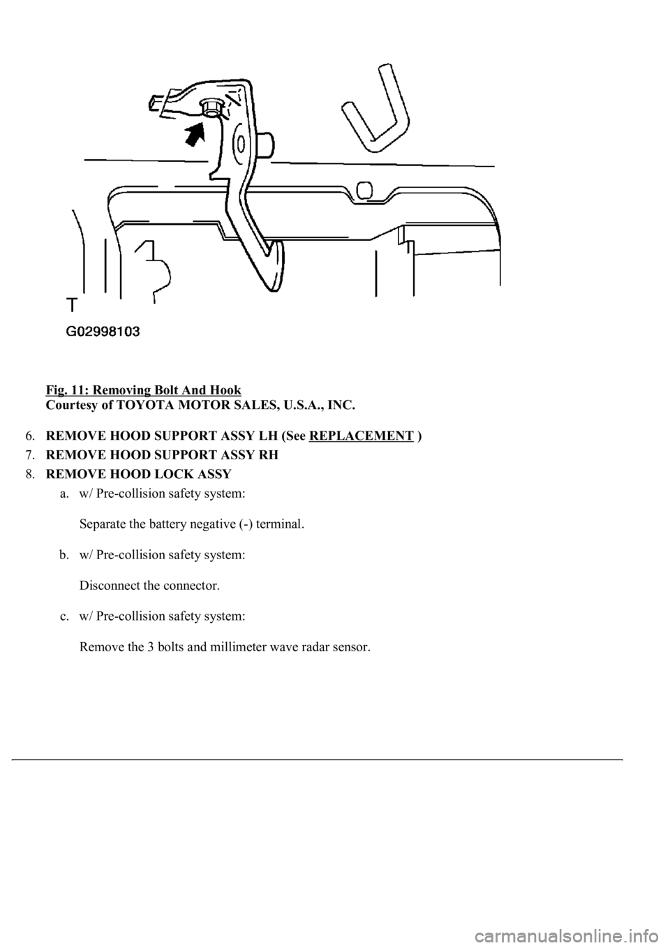
Fig. 11: Removing Bolt And Hook
Courtesy of TOYOTA MOTOR SALES, U.S.A., INC.
6.REMOVE HOOD SUPPORT ASSY LH (See REPLACEMENT
)
7.REMOVE HOOD SUPPORT ASSY RH
8.REMOVE HOOD LOCK ASSY
a. w/ Pre-collision safety system:
Separate the battery negative (-) terminal.
b. w/ Pre-collision safety system:
Disconnect the connector.
c. w/ Pre-collision safety system:
Remove the 3 bolts and millimeter wave radar sensor.
Page 3009 of 4500
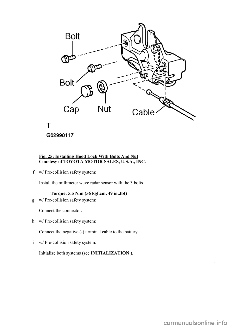
Fig. 25: Installing Hood Lock With Bolts And Nut
Courtesy of TOYOTA MOTOR SALES, U.S.A., INC.
f. w/ Pre-collision safety system:
Install the millimeter wave radar sensor with the 3 bolts.
Torque: 5.5 N.m (56 kgf.cm, 49 in..lbf)
g. w/ Pre-collision safety system:
Connect the connector.
h. w/ Pre-collision safety system:
Connect the negative (-) terminal cable to the battery.
i. w/ Pre-collision safety system:
Initialize both s
ystems (see INITIALIZATION).
Page 3010 of 4500
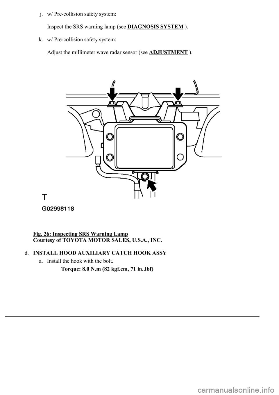
j. w/ Pre-collision safety system:
Inspect the SRS warning lamp (see DIAGNOSIS SYSTEM
).
k. w/ Pre-collision safety system:
Adjust the millimeter wave radar sensor (see ADJUSTMENT
).
Fig. 26: Inspecting SRS Warning Lamp
Courtesy of TOYOTA MOTOR SALES, U.S.A., INC.
d.INSTALL HOOD AUXILIARY CATCH HOOK ASSY
a. Install the hook with the bolt.
Torque: 8.0 N.m (82 kgf.cm, 71 in..lbf)
