LEXUS LS430 2003 Factory Repair Manual
LS430 2003
LEXUS
LEXUS
https://www.carmanualsonline.info/img/36/57050/w960_57050-0.png
LEXUS LS430 2003 Factory Repair Manual
Page 4278 of 4500
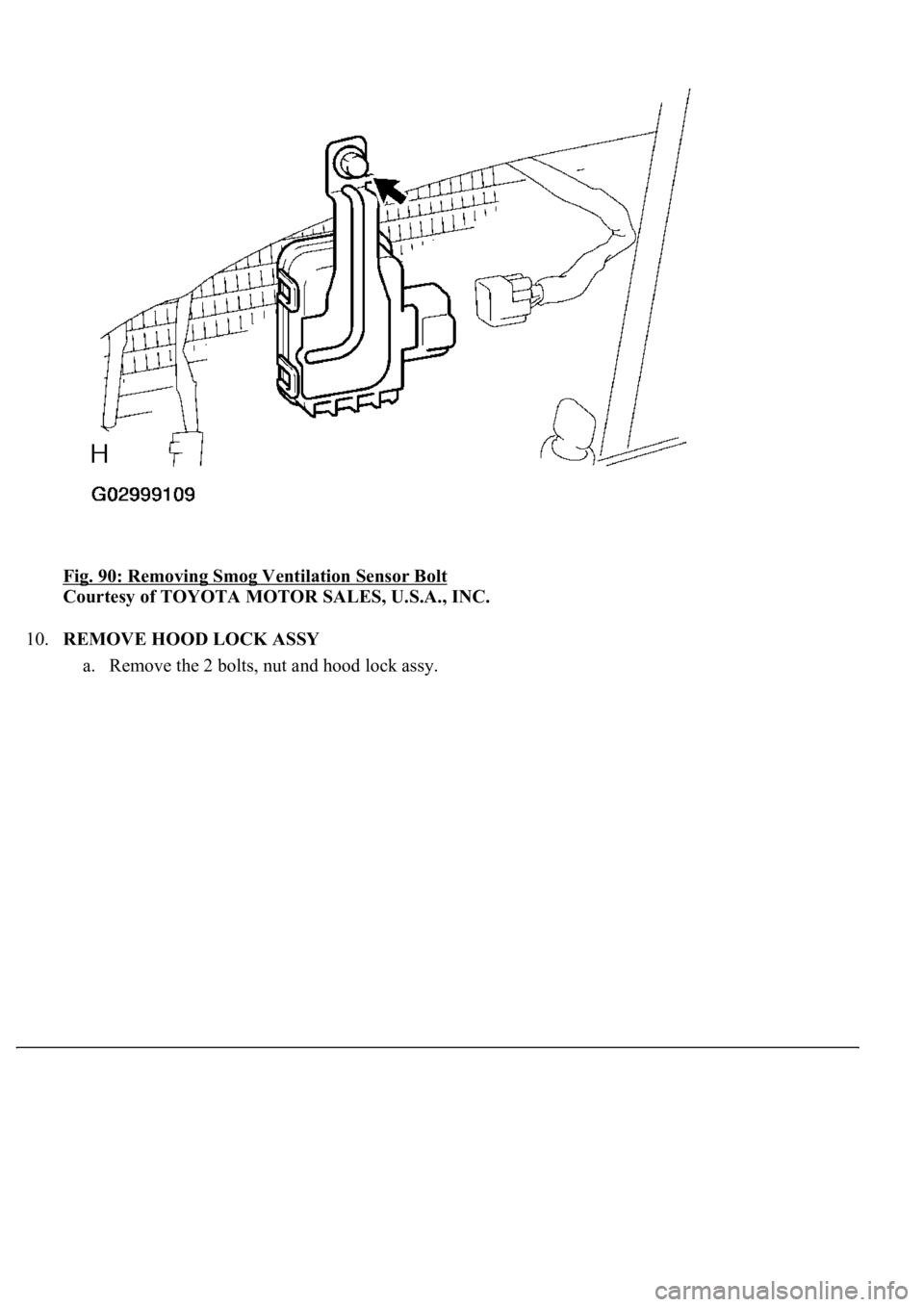
Fig. 90: Removing Smog Ventilation Sensor Bolt
Courtesy of TOYOTA MOTOR SALES, U.S.A., INC.
10.REMOVE HOOD LOCK ASSY
a. Remove the 2 bolts, nut and hood lock ass
y.
Page 4295 of 4500
INSPECTION
1.INSPECT REAR BLOWER MOTOR CIRCUIT (See REAR BLOWER MOTOR CIRCUIT
)
2.EXHAUST DAMPER CONTROL SERVOMOTOR CIRCUIT (See EXHAUST DAMPER
CONTROL SERVOMOTOR CIRCUIT )
3.INSPECT REAR MAGNETIC VALVE CIRCUIT (See REAR MAGNETIC VALVE CIRCUIT
)
4.INSPECT SMOKE SENSOR CIRCUIT (See SMOKE SENSOR CIRCUIT
)
5.INSPECT EVAPORATOR SUB-ASSY (REAR)
a. Check the evaporator sub-assy (rear) fins for blockage.
If the fins are clogged, clean them with compressed air.
b. Check the fitting for cracks or scratches.
If necessary, repair or replace.
6.INSPECT COOLING BOX LAMP SUB-ASSY
a. Connect positive (+) lead to terminal 1 and negative (-) lead to terminal 2.
b. Check that the cooling box lamp sub-assy comes on.
If coolin
g box light does not come on, replace the cooling box lamp sub-assy.
Page 4309 of 4500
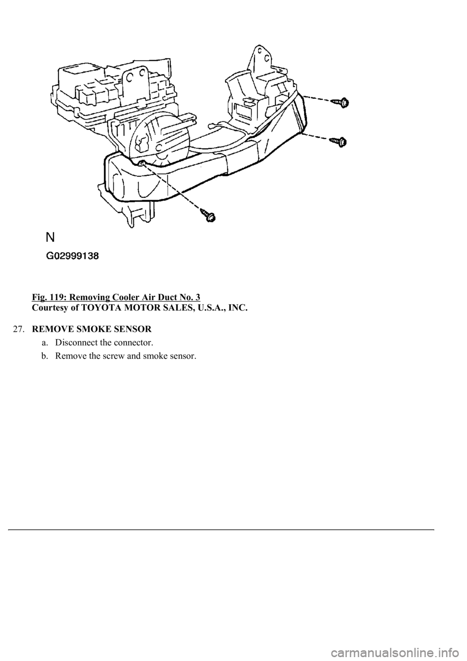
Fig. 119: Removing Cooler Air Duct No. 3
Courtesy of TOYOTA MOTOR SALES, U.S.A., INC.
27.REMOVE SMOKE SENSOR
a. Disconnect the connector.
b. Remove the screw and smoke sensor.
Page 4310 of 4500
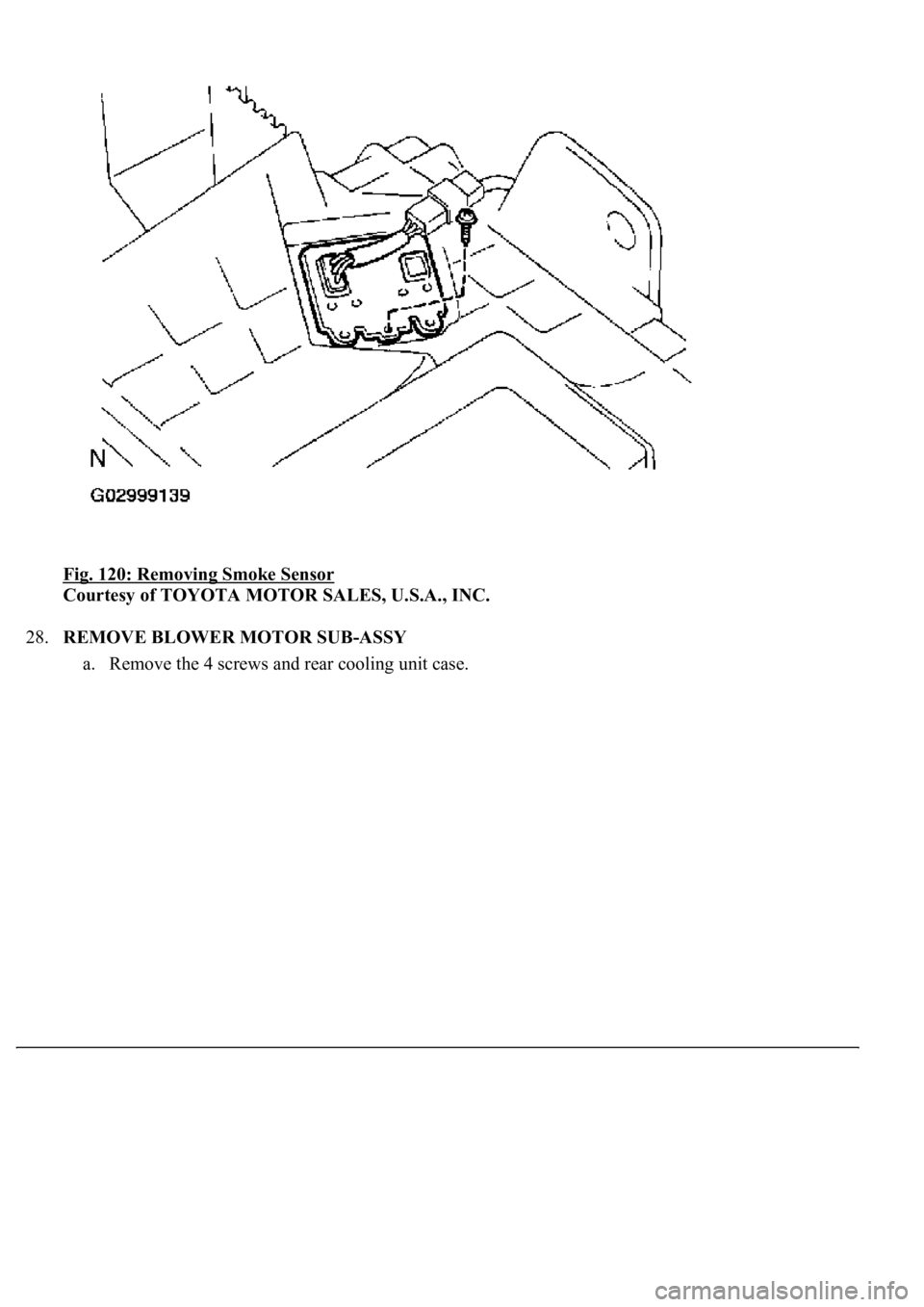
Fig. 120: Removing Smoke Sensor
Courtesy of TOYOTA MOTOR SALES, U.S.A., INC.
28.REMOVE BLOWER MOTOR SUB-ASSY
a. Remove the 4 screws and rear cooling unit case.
Page 4327 of 4500
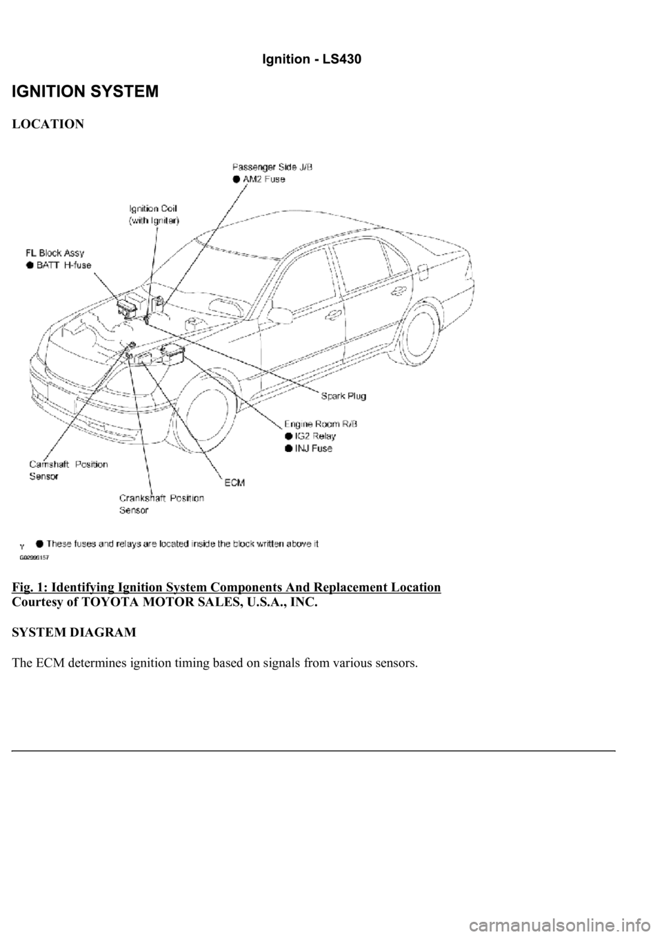
LOCATION
Fig. 1: Identifying Ignition System Components And Replacement Location
Courtesy of TOYOTA MOTOR SALES, U.S.A., INC.
SYSTEM DIAGRAM
The ECM determines ignition timing based on signals from various sensors.
Page 4336 of 4500
HINT:
Only use the spark plug cleaner when the electrode is free of oil. If the electrode has traces of oil,
use gasoline to clean off the oil before using the spark plug cleaner.
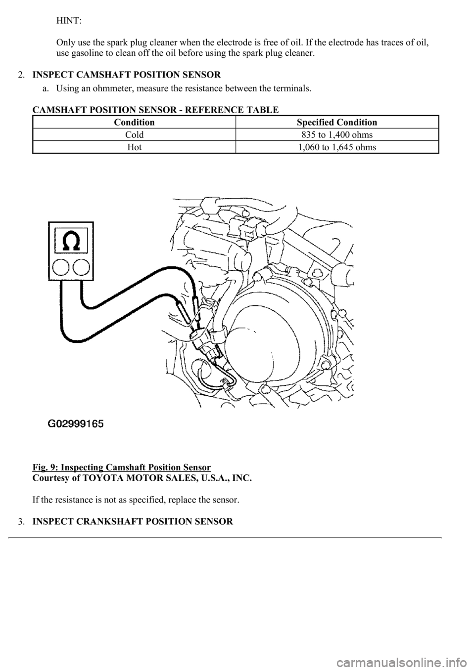
2.INSPECT CAMSHAFT POSITION SENSOR
a. Using an ohmmeter, measure the resistance between the terminals.
CAMSHAFT POSITION SENSOR - REFERENCE TABLE
Fig. 9: Inspecting Camshaft Position Sensor
Courtesy of TOYOTA MOTOR SALES, U.S.A., INC.
If the resistance is not as specified, replace the sensor.
3.INSPECT CRANKSHAFT POSITION SENSOR
ConditionSpecified Condition
Cold835 to 1,400 ohms
Hot1,060 to 1,645 ohms
Page 4337 of 4500
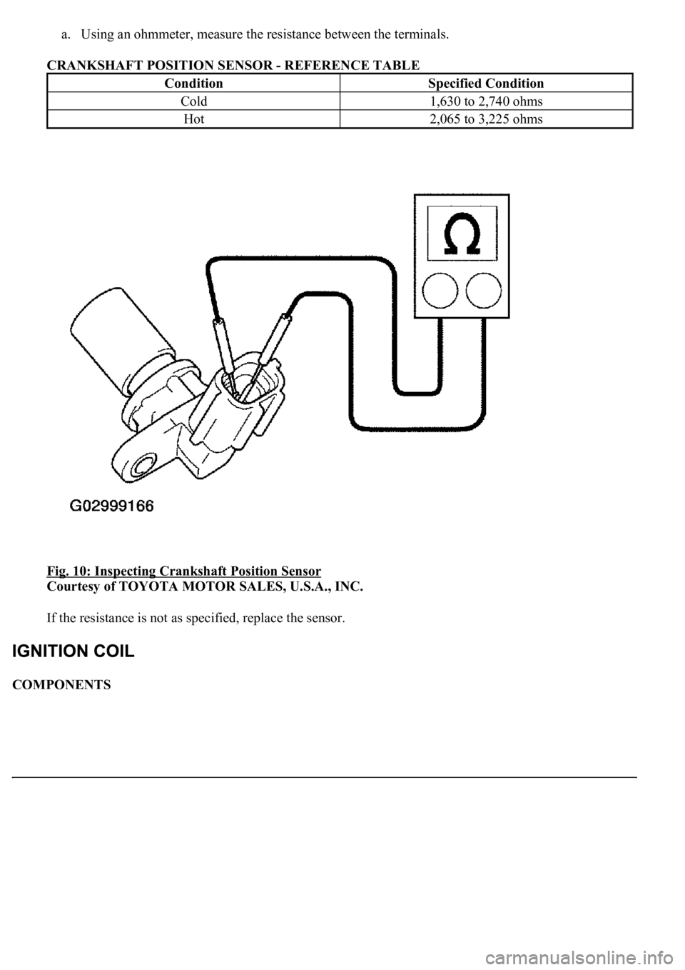
a. Using an ohmmeter, measure the resistance between the terminals.
CRANKSHAFT POSITION SENSOR - REFERENCE TABLE
Fig. 10: Inspecting Crankshaft Position Sensor
Courtesy of TOYOTA MOTOR SALES, U.S.A., INC.
If the resistance is not as specified, replace the sensor.
COMPONENTS
ConditionSpecified Condition
Cold1,630 to 2,740 ohms
Hot2,065 to 3,225 ohms
Page 4340 of 4500
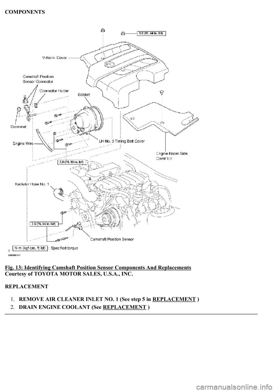
COMPONENTS
Fig. 13: Identifying Camshaft Position Sensor Components And Replacements
Courtesy of TOYOTA MOTOR SALES, U.S.A., INC.
REPLACEMENT
1.REMOVE AIR CLEANER INLET NO. 1 (See step 5 in REPLACEMENT
)
2.DRAIN ENGINE COOLANT (See REPLACEMENT
)
Page 4341 of 4500
3.REMOVE V-BANK COVER
4.REMOVE ENGINE ROOM SIDE COVER
5.DISCONNECT RADIATOR HOSE NO. 1
6.REMOVE TIMING BELT COVER SUB-ASSY NO. 3 LH (See step 18 in REPLACEMENT
)
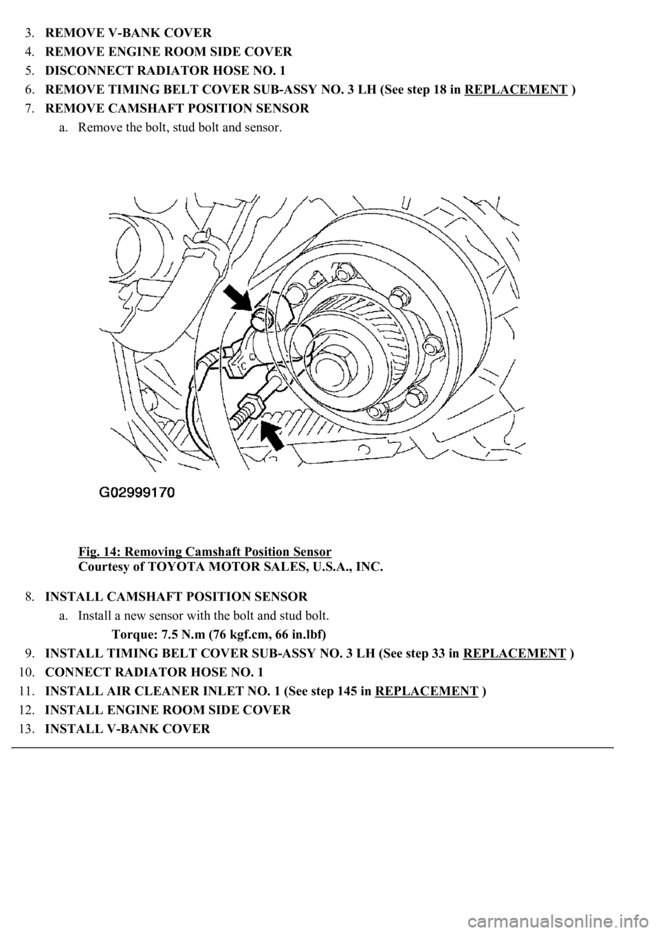
7.REMOVE CAMSHAFT POSITION SENSOR
a. Remove the bolt, stud bolt and sensor.
Fig. 14: Removing Camshaft Position Sensor
Courtesy of TOYOTA MOTOR SALES, U.S.A., INC.
8.INSTALL CAMSHAFT POSITION SENSOR
a. Install a new sensor with the bolt and stud bolt.
Torque: 7.5 N.m (76 kgf.cm, 66 in.lbf)
9.INSTALL TIMING BELT COVER SUB-ASSY NO. 3 LH (See step 33 in REPLACEMENT
)
10.CONNECT RADIATOR HOSE NO. 1
11.INSTALL AIR CLEANER INLET NO. 1 (See step 145 in REPLACEMENT
)
12.INSTALL ENGINE ROOM SIDE COVER
13.INSTALL V-BANK COVER
Page 4343 of 4500
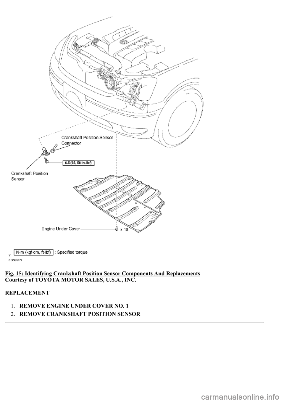
Fig. 15: Identifying Crankshaft Position Sensor Components And Replacements
Courtesy of TOYOTA MOTOR SALES, U.S.A., INC.
REPLACEMENT
1.REMOVE ENGINE UNDER COVER NO. 1
2.REMOVE CRANKSHAFT POSITION SENSOR
