LEXUS SC400 1991 Service Repair Manual
Manufacturer: LEXUS, Model Year: 1991, Model line: SC400, Model: LEXUS SC400 1991Pages: 4087, PDF Size: 75.75 MB
Page 1561 of 4087

POST ASSEMBLY
EG24Z±01
(See Components for Cylinder Block Prepation of
Disassembly and Post Assembly)
1. INSTALL WATER SEAL PLATE
(a) Remove any old packing (FIPG) material and be careful notto drop any oil on the contact surfaces of the seal plate and
cylinder block.
wUsing a razor blade and gasket scraper remove all the
old packing (FIPG) material from the gasket surfaces
and sealing groove.
w Thoroughly clean all components to remove all the
loose material.
w Using a non±residue solvent, clean both sealing
surfaces.
(b) Apply seal packing to the seal plate as shown in the illustration.
Seal packing:
Part No. 08826±00080 or equivalent
wInstall a nozzle that has been cut to 2 ± 3 mm (0.08±0.12
in.) opening.
w Parts must be assembled within 5 minutes of
application. Otherwise the material must be removed
and reapplied.
w Immediately remove nozzle from the tube and reinstall
cap.
(c) Install the seal plate with the 2 nuts. Alternately tighten the
nuts in several passes.
Torque: 14 N Vm (145 kgf Vcm, 10 ft Vlbf)
2. INSTALL GENERATOR BRACKET
Install the generater bracket with the bolt.
Torque: 18 N Vm (185 kgf Vcm, 13 ft Vlbf)
3. INSTALL OIL PUMP
(a) Remove any old packing (FIPG) material and be careful not
to drop any oil on the contact surfaces of the oil pump and
cylinder block.
wUsing a razor blade and gasket scraper, remove all the
old packing (FIPG) material from the gasket surfaces
and sealing groove.
w Thoroughly clean all components to remove all the
loose material.
w Using a non±residue solvent, clean both sealing
surfaces.
±
1UZ±FE ENGINE ENGINE MECHANICALEG±185
WhereEverybodyKnowsYourName
Page 1562 of 4087

(b) Apply seal packing to the oil pump as shown in the illustration.
Seal packing:
Part No. 08826±00080 or equivalent
NOTICE: Avoid applying an excessive amount to the sur-
face. Be particularly careful near oil passage.
w In sta ll a no zzle th a t ha s be e n cu t to a 2 ± 3 mm
(0.08±0.12 in.) opening.
w Parts must be assembled within 5 minutes of
application. Otherwise the material must be removed
and reapplied.
w Immediately remove nozzle from the tube and reinstall
cap.
(c) Install a new O±ring to the cylinder block.
(d) Engage the spline teeth of the oil pump drive gear with the large teeth of the crankshaft, and slide the oil pump on the
crankshaft.
(e) Install the oil pump with the 8 bolts. Uniformly tighten the bolts
in several passes.
Torque:
16 NVm (160 kgf Vcm, 12 ft Vlbf) for 12 mm head
30 N Vm (310 kgf Vcm, 22 ft Vlbf) for 14 mm head
HINT: Each bolt length is indicated in the illustration.
Bolt length:
50 mm (1.97 in.) for A of 12 mm head
106 mm (4.17 in.) for B of 12 mm head
30 mm (1.18 in.) for C of 12 mm head
40 mm (1.57 in.) for D of 14 mm head
EG±186
±
1UZ±FE ENGINE ENGINE MECHANICAL
WhereEverybodyKnowsYourName
Page 1563 of 4087
4. INSTALL NO.1 AND NO.2 OIL PANS(See steps 1 to 7 on pages EG±509 to 511)
5. INSTALL WATER PUMP
(a) Remove any old packing (FIPG) material and be careful not to drop any oil on the contact surfaces of the water pump and
cylinder block.
wUsing a razor blade and gasket scraper, remove all the
old packing (FIPG) material from the gasket surfaces
and sealing groove.
w Thoroughly clean all components to remove all the
loose material.
w Using a non±residue solvent, clean both sealing
surfaces.
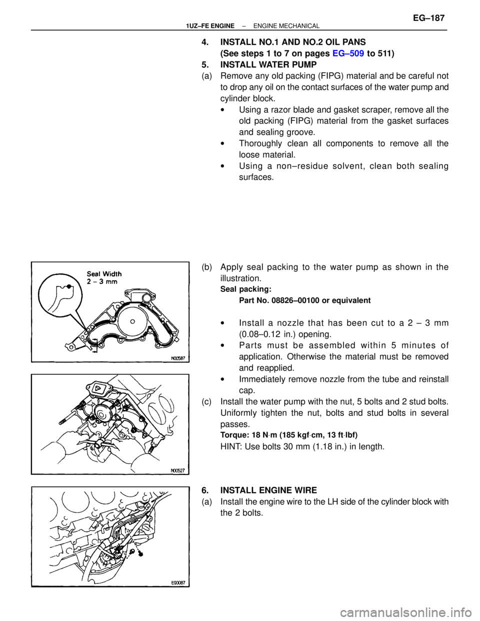
(b) Apply seal packing to the water pump as shown in the illustration.
Seal packing:
Part No. 08826±00100 or equivalent
wIn sta ll a no zzle th a t ha s be e n cu t to a 2 ± 3 mm
(0.08±0.12 in.) opening.
w Parts must be assembled within 5 minutes of
application. Otherwise the material must be removed
and reapplied.
w Immediately remove nozzle from the tube and reinstall
cap.
(c) Install the water pump with the nut, 5 bolts and 2 stud bolts. Uniformly tighten the nut, bolts and stud bolts in several
passes.
Torque: 18 N Vm (185 kgf Vcm, 13 ft Vlbf)
HINT: Use bolts 30 mm (1.18 in.) in length.
6. INSTALL ENGINE WIRE
(a) Install the engine wire to the LH side of the cylinder block with
the 2 bolts.
±
1UZ±FE ENGINE ENGINE MECHANICALEG±187
WhereEverybodyKnowsYourName
Page 1564 of 4087

(b) Install the engine wire cover with the 3 bolts.
(c) Connect the following connector:wCrankshaft position sensor connector
w Oil pressure switch connector
w Oil level sensor connector
7. INSTALL WATER BYPASS PIPE
(a) Install a new O±ring to the water bypass pipe.
(b) Apply soapy water to the O±ring.
(c) Push the water bypass pipe end into the pipe hole of the water pump.
(d) Install the water bypass pipe with the 2 bolts.
Torque: 18 N Vm (185 kgf Vcm, 13 ft Vlbf)
8. INSTALL KNOCK SENSORS
(a) Using SST, install the 2 knock sensors.
SST 09816±30010
Torque: 44 N Vm (450 kgf Vcm, 33 ft Vlbf)
(b) Connect the 2 knock sensor connectors.
9. INSTALL STARTER
(a) Install the engine wire clamp to the bracket on the starter.
(b) Connect the starter wire with the nut.
(c) Connect the starter connector.
(d) Install the starter with the 2 bolts.
Torque: 39 N Vm (400 kgf Vcm, 29 ft Vlbf)
EG±188±
1UZ±FE ENGINE ENGINE MECHANICAL
WhereEverybodyKnowsYourName
Page 1565 of 4087
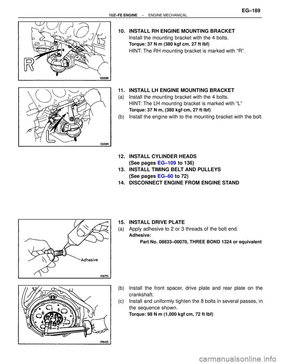
10. INSTALL RH ENGINE MOUNTING BRACKETInstall the mounting bracket with the 4 bolts.
Torque: 37 N Vm (380 kgf Vcm, 27 ft Vlbf)
HINT: The RH mounting bracket is marked with ªRº.
11. INSTALL LH ENGINE MOUNTING BRACKET
(a) Install the mounting bracket with the 4 bolts. HINT: The LH mounting bracket is marked with ªLº
Torque: 37 N Vm, (380 kgf Vcm, 27 ft Vlbf)
(b) Install the engine with to the mounting bracket with the bolt.
12. INSTALL CYLINDER HEADS
(See pages EG±109 to 136)
13. INSTALL TIMING BELT AND PULLEYS (See pages EG±60 to 72)
14. DISCONNECT ENGINE FROM ENGINE STAND
15. INSTALL DRIVE PLATE
(a) Apply adhesive to 2 or 3 threads of the bolt end.
Adhesive:
Part No. 08833±00070, THREE BOND 1324 or equivalent
(b) Install the front spacer, drive plate and rear plate on thecrankshaft.
(c) Install and uniformly tighten the 8 bolts in several passes, in
the sequence shown.
Torque: 98 N Vm (1,000 kgf Vcm, 72 ft Vlbf)
±
1UZ±FE ENGINE ENGINE MECHANICALEG±189
WhereEverybodyKnowsYourName
Page 1566 of 4087
ENGINE & TRANSMISSION ASSEMBLY
EG34U±01
(See Components for Engine & Transmission Separation and
Assembly)
1. INSTALL TRANSMISSION TO ENGINE
(See page AT±23)
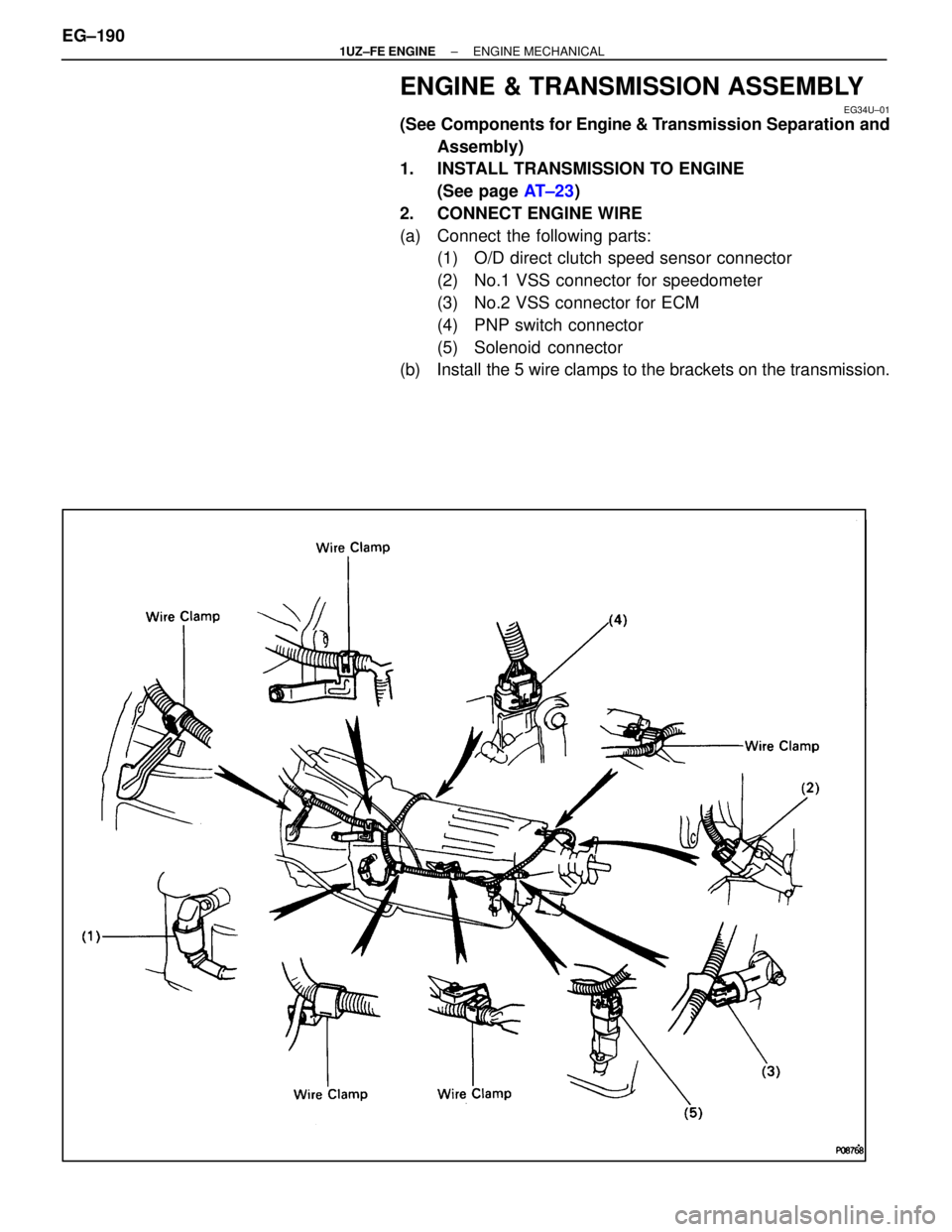
2. CONNECT ENGINE WIRE
(a) Connect the following parts: (1) O/D direct clutch speed sensor connector
(2) No.1 VSS connector for speedometer
(3) No.2 VSS connector for ECM
(4) PNP switch connector
(5) Solenoid connector
(b) Install the 5 wire clamps to the brackets on the transmission.
EG±190
±
1UZ±FE ENGINE ENGINE MECHANICAL
WhereEverybodyKnowsYourName
Page 1567 of 4087

3. INSTALL OIL COOLER PIPE FOR TRANSMISSION
(a) Temporarily install the oil cooler pipe with the 2 pipe bracketsand 2 bolts.
(b) C onnect the 2 oil cooler pipes to the unions on the
transmission.
Torque: 34 N Vm (350 kgf Vcm, 26 ft Vlbf)
(c) Tighten the 2 pipe clamp bolts.
4. INSTALL OIL DIPSTICK GUIDE AND DIPSTICK FOR
TRANSMISSION
(a) Install a new O±ring to the dipstick guide
(b) Apply soapy water to the O±ring
(c) Connect the dipstick guide end to the dipstick tube of the oil
pan.
(d) Install the dipstick guide with the bolt.
(e) Install the dipstick.
±
1UZ±FE ENGINE ENGINE MECHANICALEG±191
WhereEverybodyKnowsYourName
Page 1568 of 4087

ENGINE INSTALLATION
EG2HW±02
(See Components for Engine Removal and Installation)
1. INSTALL ENGINE AND TRANSMISSION ASSEMBLY INVEHICLE
(a) Attach the engine chain hoist to the engine hangers.
(b) Slowly lower the engine and transmission assembly into the engine compartment.
NOTICE: Be careful not to hit the PS gear housing and
PNP switch.
(c) Insert the stud bolts of the front engine mounting brackets into the stud bolt holes of the front suspension crossmember.
(d) Keep the engine level.
(e) Install the rear engine mounting member with the 4 bolts and 4 nuts.
Torque:
25 NVm (250 kgf Vcm, 19 ft Vlbf) for bolt
13 N Vm (135 kgf Vcm, 10 ft Vlbf) for nut
(f) Install the 2 nuts holding the engine mounting brackets to the
front suspension crossmember.
Torque: 59 N Vm (600 kgf Vcm, 43 ft Vlbf)
EG±192±
1UZ±FE ENGINE ENGINE MECHANICAL
WhereEverybodyKnowsYourName
Page 1569 of 4087
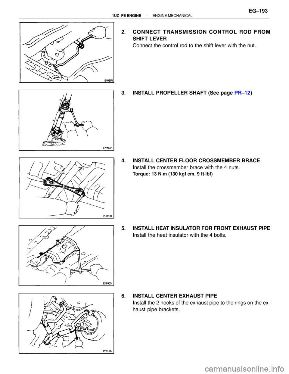
2. CONNECT TRANSMISSION CONTROL ROD FROMSHIFT LEVER
Connect the control rod to the shift lever with the nut.
3. INSTALL PROPELLER SHAFT (See page PR±12)
4. INSTALL CENTER FLOOR CROSSMEMBER BRACE Install the crossmember brace with the 4 nuts.
Torque: 13 N Vm (130 kgf Vcm, 9 ft Vlbf)
5. INSTALL HEAT INSULATOR FOR FRONT EXHAUST PIPE
Install the heat insulator with the 4 bolts.
6. INSTALL CENTER EXHAUST PIPE Install the 2 hooks of the exhaust pipe to the rings on the ex-
haust pipe brackets.
±
1UZ±FE ENGINE ENGINE MECHANICALEG±193
WhereEverybodyKnowsYourName
Page 1570 of 4087
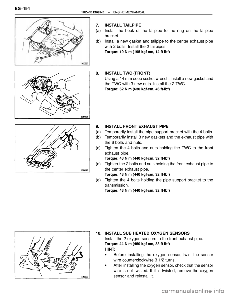
7. INSTALL TAILPIPE
(a) Install the hook of the tailpipe to the ring on the tailpipebracket.
(b) Install a new gasket and tailpipe to the center exhaust pipe with 2 bolts. Install the 2 tailpipes.
Torque: 19 N Vm (195 kgf Vcm, 14 ft Vlbf)
8. INSTALL TWC (FRONT)
Using a 14 mm deep socket wrench, install a new gasket and
the TWC with 3 new nuts. Install the 2 TWC.
Torque: 62 N Vm (630 kgf Vcm, 46 ft Vlbf)
9. INSTALL FRONT EXHAUST PIPE
(a) Temporarily install the pipe support bracket with the 4 bolts.
(b) Temporarily install 3 new gaskets and the exhaust pipe with
the 6 bolts and nuts.
(c) Tighten the 4 bolts and nuts holding the TWC to the front exhaust pipe.
Torque: 43 N Vm (440 kgf Vcm, 32 ft Vlbf)
(d) Tighten the 2 bolts and nuts holding the front exhaust pipe to
the center exhaust pipe.
Torque: 43 N Vm (440 kgf Vcm, 32 ft Vlbf)
(e) Tighten the 4 bolts holding the pipe support bracket to the
transmission.
Torque: 43 N Vm (440 kgf Vcm, 32 ft Vlbf)
10. INSTALL SUB HEATED OXYGEN SENSORS
Install the 2 oxygen sensors to the front exhaust pipe.
Torque: 44 N Vm (450 kgf Vcm, 33 ft Vlbf)
HINT:
w Before installing the oxygen sensor, twist the sensor
wire counterclockwise 3 1/2 turns.
w After installing the oxygen sensor, check that the sensor
wire is not twisted. If it is twisted, remove the oxygen
sensor and reinstall it.
EG±194
±
1UZ±FE ENGINE ENGINE MECHANICAL
WhereEverybodyKnowsYourName