MAZDA 323 1992 Suplement Manual Online
Manufacturer: MAZDA, Model Year: 1992, Model line: 323, Model: MAZDA 323 1992Pages: 279, PDF Size: 24.15 MB
Page 81 of 279

F3 CONTROL SYSTEM
Ve: Battery voltage
Termina
1N ’
10
1P
IQ
IR
IS
1T
tlJ
IV Jnput Outpul
0
0
0
0
0
0
0
0
0 Connected to
Throttle sensor
(idle switch) Test condition
Correct voltage Remark
Accelerator pedal released
Below 1.0V
lgnltlon switch
Accelerator pedal depressed
VI3 ON
Foglrght relay
P/S pressure
switch Fogtight switch ON
Fogfight switch OFF
Ignition switch ON
P/S pressure switch ON at Idle
PIS pressure switch OFF at idle Va
ov
V3
Below 1 .OV
VB -
-
A/C switch A/C switch ON
A/C switch OFF Below 23 Ignition switch
Va ’ ON and blower
motor ON
1 f Ekctrtc cooltng fan Fan operating (coolant temperature over
Below 1 .OV
switch
97OC 1207OF 1 or diagnosis connector
terminal TFA grounded) -
Fan not operating (Idle)
VI3
Blower control Blower control switch OFF or 1st position
.Va
swbtch Ignitton switch
Blower control switch 2nd or hjgher po-
Below 1 .OV ON
sition
Rear window
defroster switch Rear window defroster OFF
Rear window defroster ON Below 1 .OV Ignition switch
V0 ON
Headlight switch
Headfights ON Va
Headlights OFF -
Below 1.OV
Neutral/Clutch
Neutral position or clutch pedal
9eJow I .OV
switches
depressed
Others
Va
7
r u-.
I-I-I
f
2y 2w 2u 2s 20 20 2M 2K 21 2G 2E 2C 2A 1U 1s 10 10 1M 1K 11 rG IE tC ;A
22 2% 2V 2T 2R 2P ZN 2L 25 2H 2F 2D 28 tV 1T ‘IR IF 1N It ;J. IH IF ID 18
i
A
F3-48
-- Alwa@
Always
Always
Always
--
Always
--
Always
--
Always
--
Always
--
Always
(electric
--
Alway<;
--
Always
-e
Afway?;
I .ov
Always
--
Always
--
Alway:;
--
Page 82 of 279

-. _.. . . . . . _ - ._.
-w
CONTROL SYSTEM F3
I .
-.
Ve: Battery voltaae I
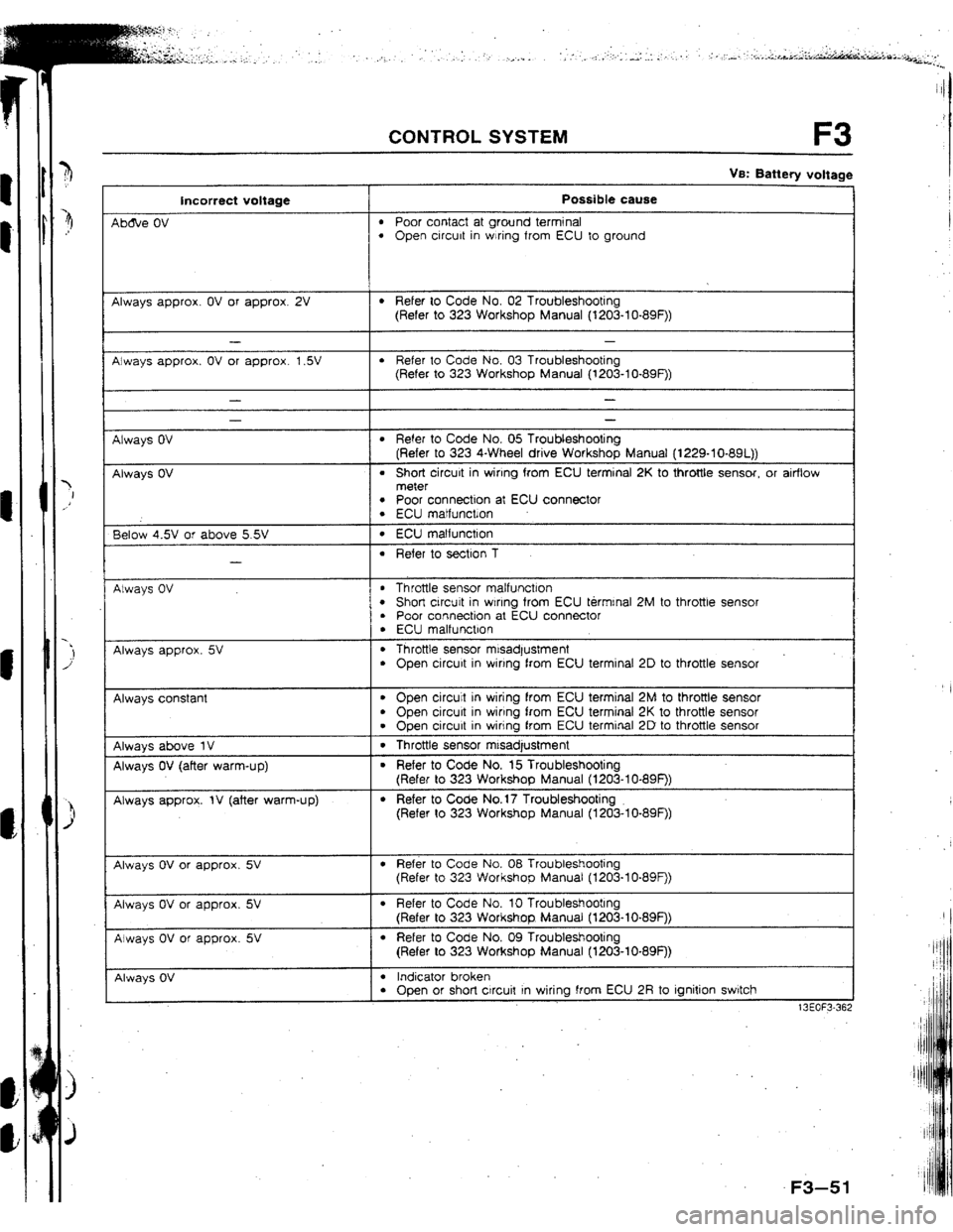
Incorrect voltage
Atwafi below 1 .OV
Always VB
Always VS (foglight switch OK)
Always below 1 .OV
Always below 1 .OV
Always Vs
Always
below 23 (blower fan OK)
Always VB (blower fan OK)
Always below 1 .OV
(electric cooling fan OK) -
1-
Possible cause
l Throttle sensor mrsadjustment l Short circuit in wtrrng from throttle sensor to ECU terminal 1 N l ECU malfunction
l Throttle sensor mrsadjustment l Open circuit in wiring from throttle sensor to ECU terminal fN l Open circuit in mnng from throttle sensor to ECU terminal 20
l Foglight relay malfunctron
l Foglrght relay malfunction
l P/S pressure switch maltunctron l Short crrcurt In wrrlng from P/S pressure switch to ECU terminal 1 P l ECU malfunction
l P/S pressure switch malfunction l Open circuit in wlnng from P/S pressure switch to ECU terminal 7 P l Open circuit in wiring from P/S pressure switch to ground
l A/C switch malfunctron l Short circuit tn wiring from A/C switch to ECU terminal 1Q l Poor connection at ECU connector l ECU malfunction
l #C swatch malfunction l Open circuit in wiring from A/C switch to ECU terminal 1Q l Open circuit in wiring from A/C switch to blower control switch
l Open or short circuit in wiring from fan relay to ECU terminal 1R l ECU matfunction
Always below 1 .OV (blower fan OK}
Always Vs (btower fan OK)
Always betow illumination lamp
1 .ov ON when rear
window defroster
switch ON
Illumination lamp
never ON
Atways below 1 .OV (headttghts OK)
l Short circuit in wrrtng from blower control switch to ECU terminal IS l Poor connection at ECU connector l ECU m&function
l Open crrcuit in wrrrng from blower control switch to ECU terminal 1s
l Open or short crrcuit In wiring from rear window defroster switch to ECU
terminal t T
l Open circuit in wiring from ignitron switch to rear window defroster switch l Rear window defroster switch malfunction
l Open or short circuit in wiring from headlight relay to ECU terminal 1 U
Always below 1 .OV
l Neutral switch malfunction l Clutch switch malfunction l Short circuit in wiring from ECU terminal IV to neutral or clutch switch
Always VB
l Neutral switch malfunction l Clutch switch malfunction l Open circuit in wiring from ECU terminal 1V to neutral or clutch swdch l Poor connection at ECU connector
13FOl=3-36 .
F3-49
.:i
Page 83 of 279

F3 CONTROL SYSTEM
Vs: Battery voltage
‘erminat Input Output Connected to Test condition
Correct voltage Remark
2A’ - - Ground (i nlector) Constant CIV -
26 - - Ground (output) Constant ov -
2C - - Ground (CPU) Constant ov -
2D - - Ground (input) Constant ov -
2E 0 Distributor Ignition switch ON QV or 5v
{NE-slgnal) -
f
r ldte
Approx. 2V
2F - - - -
- -
2G 0 Dstributor Ignition switch ON
ov or 5v
(G signal)
ldte Approx. 1.5V
a-l -I- - -
- -
21 - - - - - -
23 0 Knock control unit Idle Approx. 4.W -
I
2K 0 Throttle sensor/ Constant 4.5--5SV
Airflow meter
-
2L cl
2M 0 Speedometor
sensor
Throttle sensor Ignition switch UN
Accelerator pedal released
Accelerator pedal fully depressed 0 or 5V
Approx. 0.W
Approx. 4.W
-
2N 0
20 0
2P 0
2Q 0
2R Oxygen sensor Ignition switch ON ov
Idle (cold engine) ov
Idle (after warm-up) o- 1 .ov -
Increasing engine speed (after warm-up) 0.5-l .ov
Deceleration o--0.w
Airflow meter ignition switch ON Approx. 3.W
-
Idle Approx. 3.OV
Intake air Ambient air temperature 2O*C (68*F) Approx. 2.5V In arrflow meter
thermosensor
Water Engine’cooiant temperature 20°C (68OF) Approx. 2.W
thermosensor -
After warm-up Below 0.5V
0 Turbocharge Ignition switch ON VS
indicator -
7
r u-l 7 c Ul I-'
2y ?A’ 2u 25 20 20 2M 2K 21 ?G 2E 2C 2A 1u 1s 10 10 1M ?K 11 1G 1E 1C 1A
22 2x zv 2T 2R 2P 2N 2L 2J 2H 2F 20 28 1V 1T tR tP 1N IL 1.1 1~ qF 10 1~
F3-50
L --
4b&e (
--
Alway:
-a
--
Always
--
--
--
Always
--
Always
--
Below L
-I
--
Always
--
Alway:,
Alway:;
Alway:;
--
Alway:;
--
Always
--
Always
--
Always
Always
Page 84 of 279

CONTROL SYSTEM F3
VS: Battery voltage
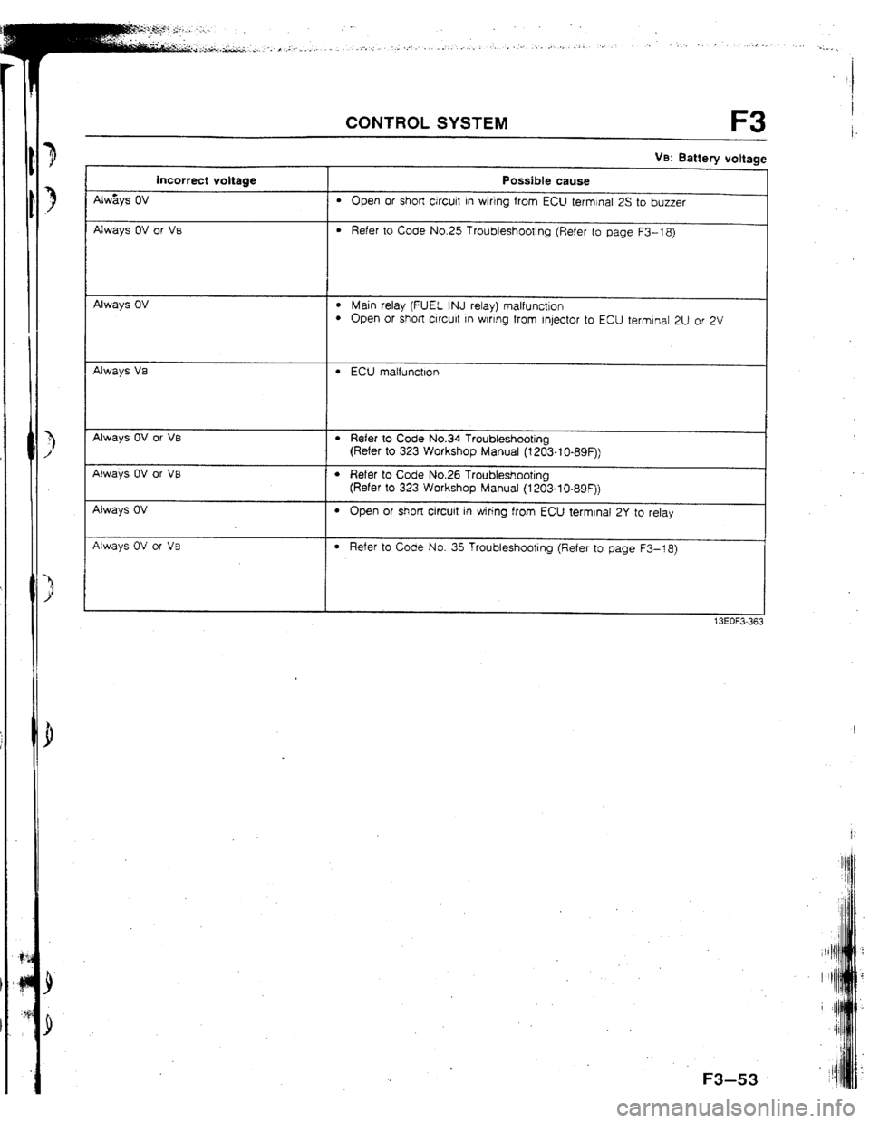
Incorrect voltage Possible cause
Ab&e OV
l Poor contact at ground terminal l Open circuit in wiring from ECU to ground
Always approx. OV or approx. 2V
l Refer to Code No. 02 Troubleshooting
(Refer to 323 Workshop Manual (l203-lo-89F))
Always approx. OV or approx. 1.5V
l Refer to Code No, 03 Troubleshooting
(Refer to 323 Workshop Manual (1203-lo-89F))
Always OV
Always OV
- -
l Refer to Code No. 05 Troubleshooting
(Refer to 323 4-Wheel drive Workshop Manual (1229-10-891))
l Short circuit in wiring from ECU terminal 2K to throttle sensor, or airflow
meter
l Poor connection at ECU connector l ECU matfunctlon
Below 4.5V or above 5.5V
-
l ECU matfunction
l Refer to section 1
Always OV
l Throttle sensor malfunction l Short circuit in wlnng from ECU termrnal 2M to throttle sensot l Poor connection at ECU connector
. ECU malfunction
Always approx. 5V . Throttle sensor misadjustment
l Open circuit in wiring from ECU terminal 2D to throttle sensor
Always constant
l Open circuit in wiring from ECU terminal 2M to throttle sensor
. Open circurt in wiring from ECU terminal 2K to throttle sensor
l Open circuit in wiring from ECU terminal 2D to throttle sensor
Always above 1V 1 . Throttle sensor mtsadjustment
Always OV (after warm-up)
Always approx. IV (after warm-up)
l Refer to Code No. 15 Troubleshooting
(Refer to 323 Workshop Manual (1203-I O-89F))
l Refer to Code No.17 Troubleshooting
(Refer to 323 Workshop Manual (1203-lo-89F))
Always OV or approx. 5V
l Refer to Code No. 08 Troubleshooting
(Refer to 323 Workshop Manual (t203-lo-89F))
Always OV or approx. 5V
Always OV or approx. 5V
l Refer to Code No. 10 Troubleshooting
(Refer to 323 Workshop Manual (l203-lo-89F))
l Refer to Code No. 09 Troubleshooting
(Refer to 323 Workshop Manual (1203-10.89F))
Always OV
I
l Indicator broken l Open or short circuit In wiring from ECU 2R to ignition switch
13EOF3-36;
F3
Page 85 of 279

F3 CONTROL SYSTEM
Terminal Input Dutpui
2s - 0
2T 0
2U 0
2v 0
2w 0
2x 0
2Y 0
22 0 t
I, Ve: Battery voltage I I I Connected to Test condition
Correct voltage Remark
Overboost warning lgnitron switch ON
VB
-
buzzer
Solenoid valve
(PRC low temp.) 180 sec. after engrne started with coolant Below 1.W No-load engine
temperature is above 9O*C { 194*F ] and condition
intake air temperature IS between 40°C
1104*FJ and 50°C {122OF
f Other condition at idle
I VS
tnjector {Nos. 1, 3) Ignition switch ON VS
Idle V0’
I Engine speed above 2,000 rpm during
I Ve
deceleration (after warm-up)
Injector (Nos 2, 4) Ignition switch
ON VS
Idle VS’ * Engine Signal
Monrtor: Green
and red lamps
flash
ISC valve Engine speed above 2,000 rpm during VS
deceleration (after warm-up)
Ignition switch ON Approx. 7V
-
Idle 1 Approx. 9V
Solenoid valve
(purge control) Ignition switch ON
Idle V0
-
VB
Ci rcuit-opening
relay ignition switch ON
tdle 1 VB
I 8elow l.OV -
Solenotd valve
(PRC high temp.) 210 sec. after engine started wrth coolant Below 1.5V
temperature above 90°C ]194*F] and
Intake atr temperature above 50°C
f t22*F1 No-load engine
cond$on
1 Other condition at idle
I VB
I -
7 I PI
I l-1 t
r
2'f 2W 2U 25 iQ 20 &A 2K 21 2G 2E 2C 2A 1U 1s 10 10 1M 1K 11 tG If 1C 1A
F3-52 --
A/w&
--
Alway
--
Alway
--
Alway
--
Alwaj
--
Alwa f
--
Alwas]
--
Alwa I’
Page 86 of 279

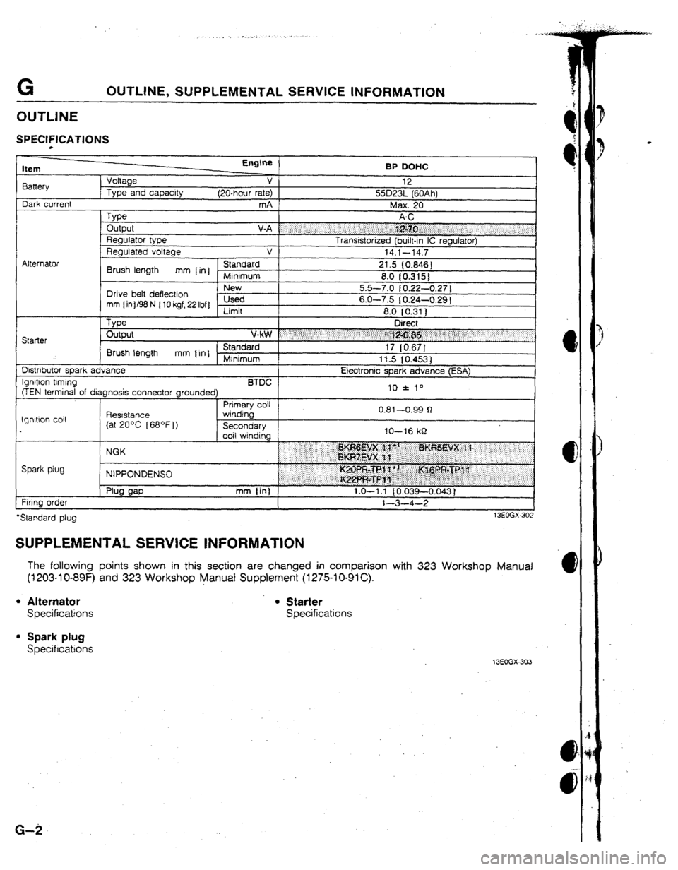
VB: Battery voltage
Incorrect voltage Possible cause
Always OV
l Open or short &curt in wirtng from ECU terminal 25 to buzzer
Always OV or VB
l Refer to Code No.25 Troubleshooting (Refer to page F3-18)
-
Always OV l Main relay (FUEL INJ relay) malfunction l Open or short crrcult rn wlnng from Injector to ECU termtnal 2U or 2V
Always Va
l ECU matfunctlon
Always OV or VB
Always OV or VB
Always OV
Atways OV or VB
l Refer to Code No.34 Troubleshooting
(Refer to 323 Workshop Manual (1203-t O-89F))
l Refer to Code No.26 Troubleshooting
(Refer to 323 Workshop Manual (1203-lO-89F))
l Open or short circuit in wiring from ECU terminal 2Y to relay
l Refer to Code No. 35 Troubleshooting (Refer to page F3-18)
F3-53
Page 87 of 279

ENGINE ELECTRICAL SYSTEM
OUTLINE ................................................... G- 2
SPECIFICATIONS .................................... G- 2
SUPPLEMENTAL SERVICE tNFORMATlON .m G- 2
13EOGX-30 t
G
Page 88 of 279

G OUTLINE, SUPPLEMENTAL SERVICE INFORMATION
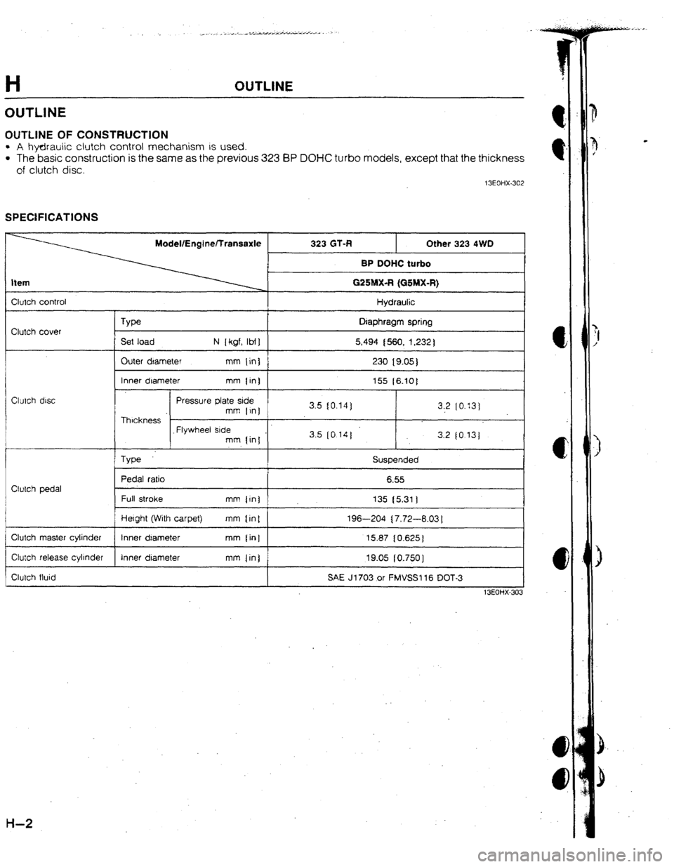
SPECIFfCATfUNS
Item
8attery
Dark current Voltage
Type and capacity Engine
v
(20-hour rate)
mA BP DOHC
12
55D23L (60Ah)
Max. 20
Type Output V-A f “‘i j.,: i .:.. ‘:.. ,, j j.: i.‘: ;:;:i :j;&?.:. .: .:.
__ : . . s.i-....‘:‘:. _.. j ;.’
Regulator type Transistorized (built-in IC regulator)
Regulated voltage v
14.1-14.7
I
C?*..*rlrrrl
Brush length mm [rn] }e 21.5 (0.846)
8.0 10.315)
I Drive belt deflection I 5.5-7.0 { 0.22-0.27 )
mm (intB8N (lOkgf,22Ibf) usea 6.0-7.5 (0.24-0.29 1
Limit 8.0 (0.311
, Type Direct
Starter Output v*$# : : ;..;. ‘:‘.. ._ .; : :‘: 7.:
.. .::“:.:j 1 ,5
. . . . .j$$g;g$y .“. :yy
Brush length mm {in] - Standard 17 [0.67]
Minimum
11.5 IO.4531
Dlstnbutor soark advance Electronic soark advance (ESA)
@EN termind of diagnosis connector grounded) II) f lo
I 1 Prtmary coil
**4 nn*
Ignltbon co11 Reststance 3
(at 20°C [68*F])
in IO-16 kQ lgnrtlon timing BTDC f ar
wrndfnb
I
Secondary 1
coil WindIn.. v.0 I
--v.yy 1
Spark plug NGK
NIPPONDENSU
Firing oraer
*Standard pfug
SUPPLEMENTAL SERVICE INFORMATION
The following points shown in this section are changed in comparison with 323 Workshop Manual
(1203-l O-89F) and 323 Workshop Manual Supplement (I 275-l O-91 C).
l Alternator . Starter
Specifications Specifications
l Spark plug
Specifications
13EGGX-303
G-2
Page 89 of 279

CLUTCH
1 FEATURES 1
OUTL!NE
..................................................
OUfLlNE OF CONSTRUCTION
.................
;I f SPECIFtCATlONS
....................................
H- 2
13EOtiX-301
H
3
,
1
$
i
r’ :
Page 90 of 279

OUTLINE
OUTLINE OF CONSTRUCTlON
l A hydraulic clutch control mechanism IS used.
l The basic construction is the same as the previous 323 BP DOl-fC turbo models, except that the thickness
of clutch disc.
t3EOHX-302
SPECIFICATIONS
I Clutch control
1 Hydraulic
I
Clutch cover
Type
Set load N [kgf, lbf] Diaphragm spring
5,494 (560, 1,232)
Outer dlarneter mm {in)
230 19.05)
1
1 Inner diameter mm {in) 1
155 [6.10]
Clutch disc Pressure plate side
mm {ini 3.5 (0.14) 3.2 [0.13]
1 Thickness 1 I
I
_ Flywheel Btde
mm {in1 . 3.5 (0 14)
3.2 (0.13j
Type Suspended
Pedal ratio 6.55
Clutch pedal
Full stroke mm ijn]
I 135 t5.311
1
I Hetght (With carpet)
mm tin{ 196-204 { 7.72-6.03 1
1 Clutch master cylinder 1 tnner dtameter mm [in] 15.87 10.625)
I
1 Ctutch release cylinder
1 Inner diameter mm {in)
I 19.05 [0.7501
I
Clutch fluid SAE 31703 or FMVSSI 16 DOT-3
1
13EOHX-303
H-2