MAZDA 323 1992 Workshop Manual Suplement
Manufacturer: MAZDA, Model Year: 1992,
Model line: 323,
Model: MAZDA 323 1992
Pages: 279, PDF Size: 24.15 MB
MAZDA 323 1992 Workshop Manual Suplement
323 1992
MAZDA
MAZDA
https://www.carmanualsonline.info/img/28/57055/w960_57055-0.png
MAZDA 323 1992 Workshop Manual Suplement
Trending: service, spark plugs replace, maintenance schedule, oil pressure, brake pads replacement, jump start terminals, clock
Page 101 of 279
FRONT AXLE M
13EOMX-317
I
I 13EOMX-311 3
3. Press out the bearing race by using the SST.
Wheel bearing
Caution
l Do not reuse the wheel bearing.
Remove the wheel bearing by using the SST.
Dust cover
Caution
l Do not remove the dust cover if not necessary.
1
l Do not reuse the dust cover If removed. ’
I. Mark the dust cover and steering knuckle for proper reas-
sembly.
2. Remove the dust cover by using a chisel.
Hub boft
caution
l Do not remove the hub bolts if not necessary.
l Do not reuse the hub bolts if removed.
Remove the hub bolts by using a press.
Assembly note
Hub bolt
Press in new hub bolts.
M-9. /,
I
Page 102 of 279
M FRONT AXLE
13EOMX-320
L 13EOMX-321
i . 13EOMX-32 13EOMX-322
3
Dust cover
1. Mark the new dust cover as the one removed.
2. Align the marks of the new dust cover and the steering
knuckle.
3. install the dust cover by using a steet plate and the SST.
Wheef bearing
lnstail the new wheel bearing by using the SST.
Front wheel hub assembly
1. Install the front wheel hub assembly by using the SST.
2. Verify that the wheel hub rotates smoothly.
Oil seal
Caution
l Use a new oil seal, and apply grease to the lip of
the seal.
‘0 tnstatt the oil seat flush with the steering knuckle.
Install the new oil seal by using the SST,
REA
PREP.
SST *
49 FO:
Pulter.
49 GOi
Hand E
(Part 3
49 GOi
49 FOE
Attach r
(Part 01
49 FOZ
--
49 FO2
Attach n
68 & 7’
(Part of
49 FO:!
--
49 FO:!’
t nstaller
bearing
--
49 GO3
Matter
49 G03:
lnstallef,
XW3
1
I 13EOMX-324 M--l 0
Page 103 of 279
_.:__ _:
M
I
REAR AXLE
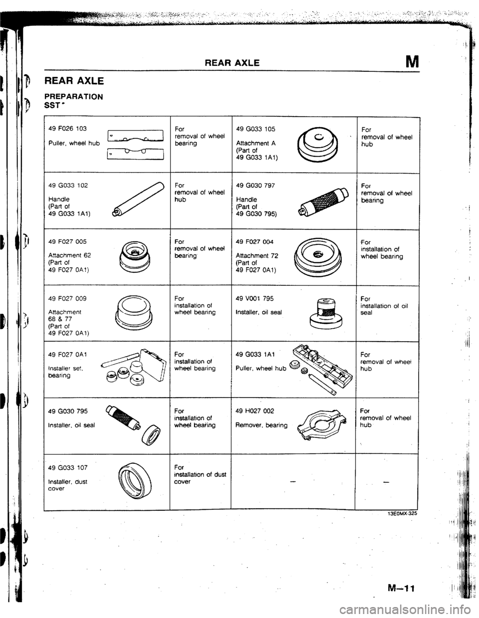
REAR
AXLE
PREPARATlON
SST’
49 FO26 103
Puller, wheel hub [cl Ei;;l of wheel ~a~~e~~~ ’ i!ovat of wheel
I- (Part of
49 GO33 1Al)
49 GO33 102
Handle
(Part of
49 GO33 1At) FC?r 49 GO30 797 For
removal of wheel removal of wheel
hub ktandte
bearing
(Part of
49 GO30 795)
49 FO27 005
Attachment 62
(Part of
49 FU27 OAf)
49 F027 009
Attachment
68 & 77 For 49 F027 004
f Of
removal of wheel installation of
bearing Attachment 72 wheel bearing
(Part of
49 F027 OAl)
installation of oil
Installer, oit seat
Instatter, oil seat Remover, bearing oval of wheel
49 GO33 107
Installer, dust
cover installation of dust
t3EOMX-32!
F
. i
t
I
Ii/
I
1
1
Page 104 of 279

REAR AXLE
WHEEL HUB, KNUCKLE
Removal I Inspection / installation
1. Remove in the order shown in the figure, referring to
Removal Note. 2. Inspect all parts and repair or replace as necessary.
3. Install in the reverse order of removal, referring to Installation Note.
Caution
l Loosely tighten the shock absorber bolts. Lower the vehicle and tighten the bolts to the specified
torque with the vehicle unladen.
4. Adiust the rear wheel alianment.
16-22 1?.6-2.3, 12-16 I
7
IO.o-13.0,
66-66.7 1 1. Wheel and tire
2. Locknut
Removal Note..; . . . . . . . . , . . . . ,.......- -.. page M-f 3
Installation Note .._...,.,...._.__........ page M-13
I$ Brake caliper assembly
Service . . . . . . . . . . . ..e......._......... ,.,...,....
Section P
4. Disc plate
‘Service ..I....................__....... . . . . . . . . . Section P 5. Af3S wheel speed sensor (if equipped)
6. Wheel hub, knuckle
Disassembly I Inspect& /
Assem bty . . . . . . . ..I..........*..*.*...-... page M-14
Inspect wheel hub and knuckle for damage
or cracks
Inspect dust cover for damage or defor-
mation
M-12
Page 105 of 279
REAR AXLE M
Removal note
Locknut
Caution
l Do not damage the drive shaft.
l Do not reuse the locknut.
I. Raise the staked portion of the tocknut using a chisel.
2. Lock the hub by applying the brakes.
3. Remove the locknut.
1 13EOMX-308
13EOMX-327 installation note
Locknut
Install a new locknut and stake it, as shown.
Tightening torque: 236-318 N-m
[ 24.0-32.5 kgfm, f 74-235 ftelbf
‘I
Page 106 of 279

M REAR AXLE
Disassembly ! Inspection ! Assembly
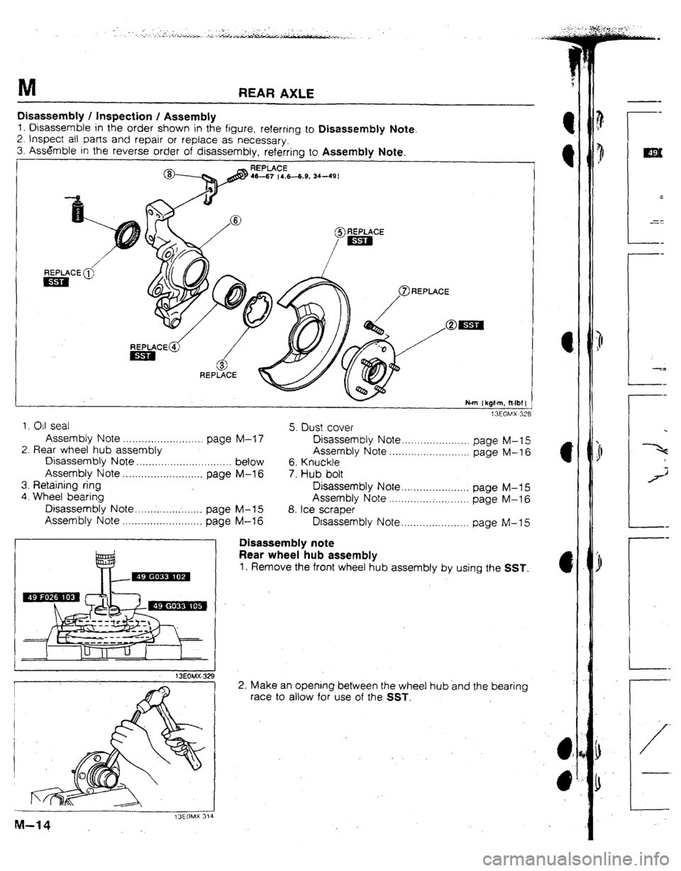
1, Disassemble in the order shown in the figure, referring to Disassembly Note.
2. Inspect ail parts and repair of replace as necessary.
3. Assemble in the reverse order of disassembly, referring to Assembly Note.
13EOMX-328
L
1. CM seal
Assembfy Note . . . . . . . . . . . . . . . . . . . . . . . . . . page M-f 7
2. Rear wheel hub assembly
Disassembly Note. . . . . . . . . . . , , ,...... . . . . . . . . , . . below
Assembly Note . . . . . . . . . . . . . . . . . . . . . . . . . . page M-l 6
3. Retaining ring
4. Wheel bearing
Disassembly Note .,.... ~ . . . . ..=........ page M-15
Assembly Note .+.................. _ . . . . . page M-l 6 5. Dust cover
Disassembly Note . . . . . . . . . . . . . . . . . . . . . page M-t 5
Assembly Note . . . . . . . . . . . . . . . . . . . . . . . . . . page M-16
6. Knuckle
7. Hub bolt
Disassembly Note . . . . . . . . . . . . ..‘....... page M-l 5
Assembly Note k.. . . . . . . . . . . . :. . . . . . . . . . . page M-l 6
8. tee scraper
Disassembly Note . . . . . . . . . . . . . . . . . . . . . . page M-f 5
13EOMX-32 9
r
I
I
1
13EOMX 314
M-14 Disassembly note
Rear wheel hub assembly
1. Remove the front wheel hub assembly by using the SST.
2. Make an opening between the wheel hub and the bearing
race to allow for use of the SST.
--
ma
=
-zt:
--
--
5=
--
--
I
1
j
-a
--
--
/-
Page 107 of 279
REAR AXLE
13EOMX-330
13EOMX-331
I
t3EOMX.318
. _.
-.
3. Press out the bearing race by using the SST.
Wheel bearing
Remove the wheel bearing by using the SST.
Dust cover
Caution
l Do not remove the dust cover if not necessary.
l Do not reuse-the dust cover if removed.
1. Mark the dust cover and steering knuckle for proper reas- *
sembly.
2. Remove the dust cover by using a chisel.
Ice scraper
Caution
l Do not remove the ice scraper if not necessary.
. If it is removed, use a new bolt applied specified
thread locking compound.
Hub bolt
caution
l Do not remove the hub bolts if not necessary.
i Do not reuse the hub bolts if removed.
Remove the hub bolts by using a press.
.
M-q.5
Page 108 of 279
M REAR AXLE
.
I
I
13EOMX-319
I
1 SEOMX -3;
13EOMX-33
1
M-16 f3EOMX-32:
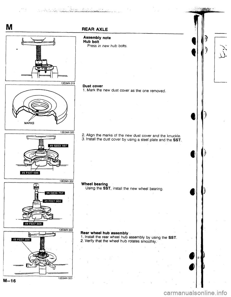
Assembly note
Hub bolt
Press in new hub bolts.
Dust cover
1. Mark the new dust cover as the one removed.
2. Align the marks of the new dust cover and the knuckle.
3. Install the dust cover by using a steel plate and the SST.
Wheel bearing
Using the SST, install the new wheel bearing.
Rear wheel hub assembly
1. Install the rear wheel hub assembly by using the SST.
2. Verify that the wheel hub rotates smoothly..
Page 109 of 279
REAR AXLE M
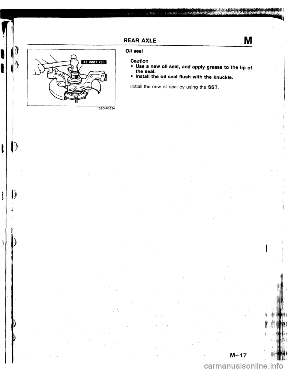
n Oil seal
Caution
l Use a new oil seal, and apply grease to the lip of
the seal.
l Install the oil seal flush with the knuckle.
install the new oil seal by using the SST.
?3EOMX-324
I
I i
Page 110 of 279
STEERING SYSTEM
OUTLINE .~.*.*....~-.**.~..*...*.*.....,*.*..~.,.~~*..,..,
N- 2
OUTIJNE OF CONSTRUCTiON mm......- . . . . . . a. N-
2
SPEClFtCATlONS .*....*........*.sm....*............
N- 2
13EONX-301
Trending: automatic transmission fluid, fuse box location, light, alternator belt, maintenance, battery, engine oil


