lock MAZDA 6 2002 Suplement User Guide
[x] Cancel search | Manufacturer: MAZDA, Model Year: 2002, Model line: 6, Model: MAZDA 6 2002Pages: 909, PDF Size: 17.16 MB
Page 52 of 909

CYLINDER HEAD GASKET
B2–21
B2
Fuel Injection Pipe Installation Note
Caution
•Fuel injection pipes can be removed and reinstalled up to five times. If removing them for the sixth
time, be sure to replace them with new ones.
Cylinder Head Cover Installation Note
1. Apply silicone sealant to the shaded areas.
Thickness
2 mm {0.079 in}
2. Tighten the bolts in the order shown.
Tightening torque
7.9—10.7 N·m {80—110 kgf·cm, 69.5—95.4
in·lbf}
Seal Plate Installation Note
1. Install the seal plate and hand tighten the bolt in
the order A to B.
2. Tighten the bolts in the order shown.
Tightening torque
7.9—10.7 N·m {80—110 kgf·cm, 69.5—95.4
in·lbf}
Idler Installation Note
Caution
•The idler has a front and back relative to
the engine, therefore when installing
make sure that the longer projection of
the shaft is on the engine side as
indicated in the figure.
SEALANTSEALANTSEALANTSEALANT
SEALANTSEALANT20 mm
{0.79 in}
MIN.VIEW AVIEW A
A6E2318W116
9
8
7
5
4
36
1
2
A6E2318W117
1
2B
A
3
3
A6E2318W118
SHAFTCYLINDER
BLOCK
BOLT
A6E2318W121
Page 53 of 909
B2–22
CYLINDER HEAD GASKET
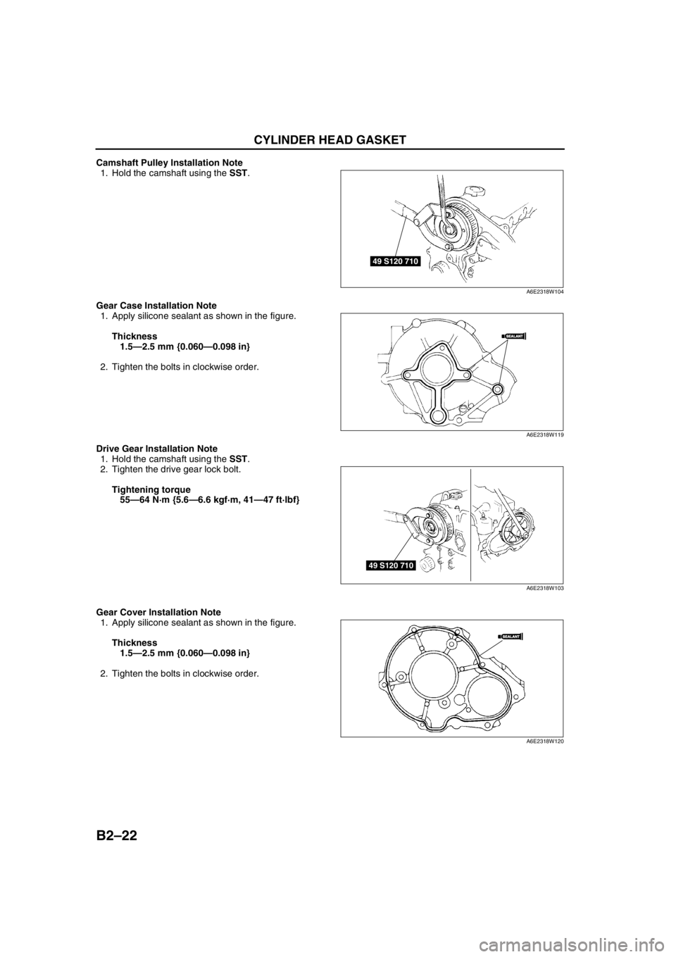
Camshaft Pulley Installation Note
1. Hold the camshaft using the SST.
Gear Case Installation Note
1. Apply silicone sealant as shown in the figure.
Thickness
1.5—2.5 mm {0.060—0.098 in}
2. Tighten the bolts in clockwise order.
Drive Gear Installation Note
1. Hold the camshaft using the SST.
2. Tighten the drive gear lock bolt.
Tightening torque
55—64 N·m {5.6—6.6 kgf·m, 41—47 ft·lbf}
Gear Cover Installation Note
1. Apply silicone sealant as shown in the figure.
Thickness
1.5—2.5 mm {0.060—0.098 in}
2. Tighten the bolts in clockwise order.
49 S120 710
A6E2318W104
SEALANTSEALANT
A6E2318W119
49 S120 710
A6E2318W103
SEALANTSEALANT
A6E2318W120
Page 55 of 909
B2–24
FRONT OIL SEAL
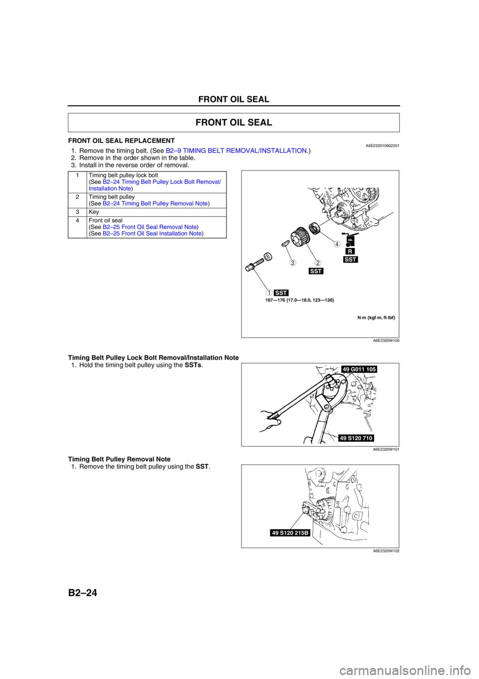
FRONT OIL SEAL REPLACEMENTA6E2320106022011. Remove the timing belt. (See B2–9 TIMING BELT REMOVAL/INSTALLATION.)
2. Remove in the order shown in the table.
3. Install in the reverse order of removal.
.
Timing Belt Pulley Lock Bolt Removal/Installation Note
1. Hold the timing belt pulley using the SSTs.
Timing Belt Pulley Removal Note
1. Remove the timing belt pulley using the SST.
FRONT OIL SEAL
1 Timing belt pulley lock bolt
(See B2–24 Timing Belt Pulley Lock Bolt Removal/
Installation Note)
2 Timing belt pulley
(See B2–24 Timing Belt Pulley Removal Note)
3Key
4 Front oil seal
(See B2–25 Front Oil Seal Removal Note)
(See B2–25 Front Oil Seal Installation Note)
SST
SST
SST
R
OILOIL
167—176 {17.0—18.0, 123—130}
N·m {kgf·m, ft·lbf}
3
1
2
4
A6E2320W100
49 G011 105
49 S120 710
A6E2320W101
49 S120 215B
A6E2320W102
Page 75 of 909
OIL PAN
D–11
D
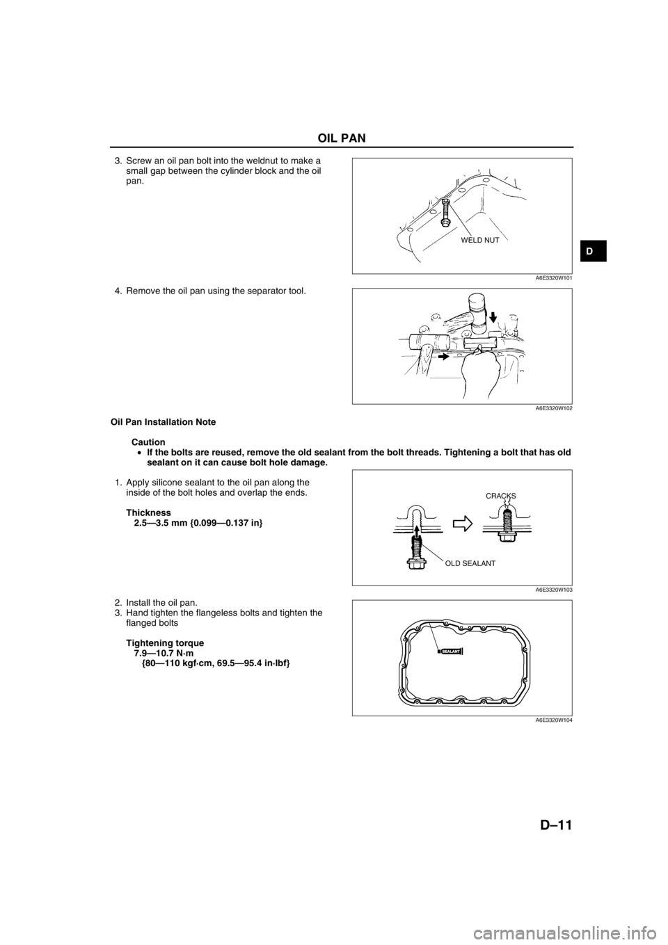
3. Screw an oil pan bolt into the weldnut to make a
small gap between the cylinder block and the oil
pan.
4. Remove the oil pan using the separator tool.
Oil Pan Installation Note
Caution
•If the bolts are reused, remove the old sealant from the bolt threads. Tightening a bolt that has old
sealant on it can cause bolt hole damage.
1. Apply silicone sealant to the oil pan along the
inside of the bolt holes and overlap the ends.
Thickness
2.5—3.5 mm {0.099—0.137 in}
2. Install the oil pan.
3. Hand tighten the flangeless bolts and tighten the
flanged bolts
Tightening torque
7.9—10.7 N·m
{80—110 kgf·cm, 69.5—95.4 in·lbf}
End Of Sie
WELD NUT
A6E3320W101
A6E3320W102
OLD SEALANTCRACKS
A6E3320W103
SEALANTSEALANT
A6E3320W104
Page 79 of 909
E–4
COOLING SYSTEM
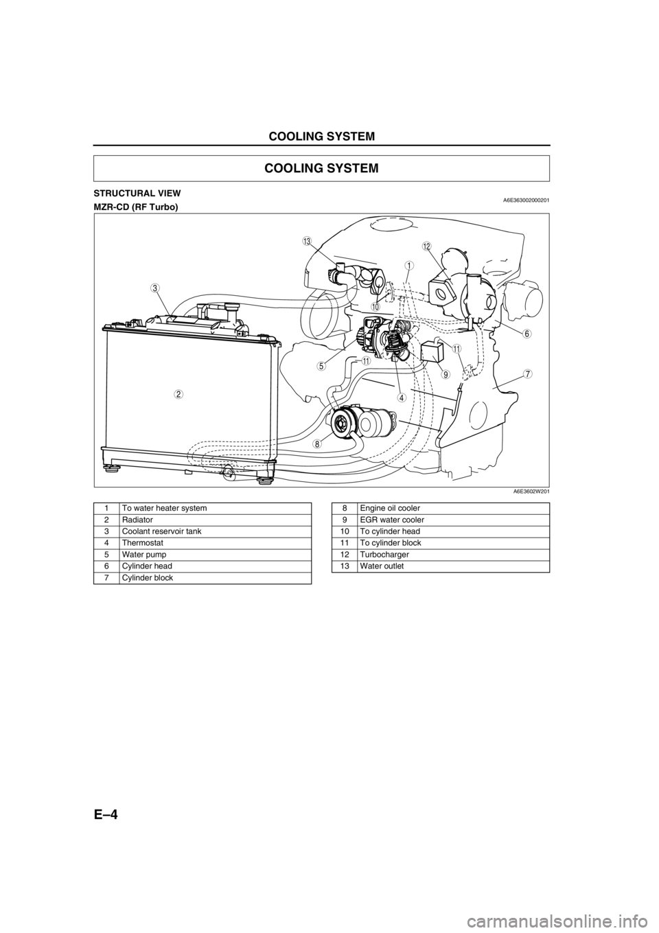
STRUCTURAL VIEWA6E363002000201MZR-CD (RF Turbo)
.
End Of Sie
COOLING SYSTEM
8
75
4
3
1
2
6
10
11
11
9
1312
A6E3602W201
1 To water heater system
2 Radiator
3 Coolant reservoir tank
4Thermostat
5 Water pump
6 Cylinder head
7 Cylinder block8 Engine oil cooler
9EGR water cooler
10 To cylinder head
11 To cylinder block
12 Turbocharger
13 Water outlet
Page 80 of 909
COOLING SYSTEM
E–5
E
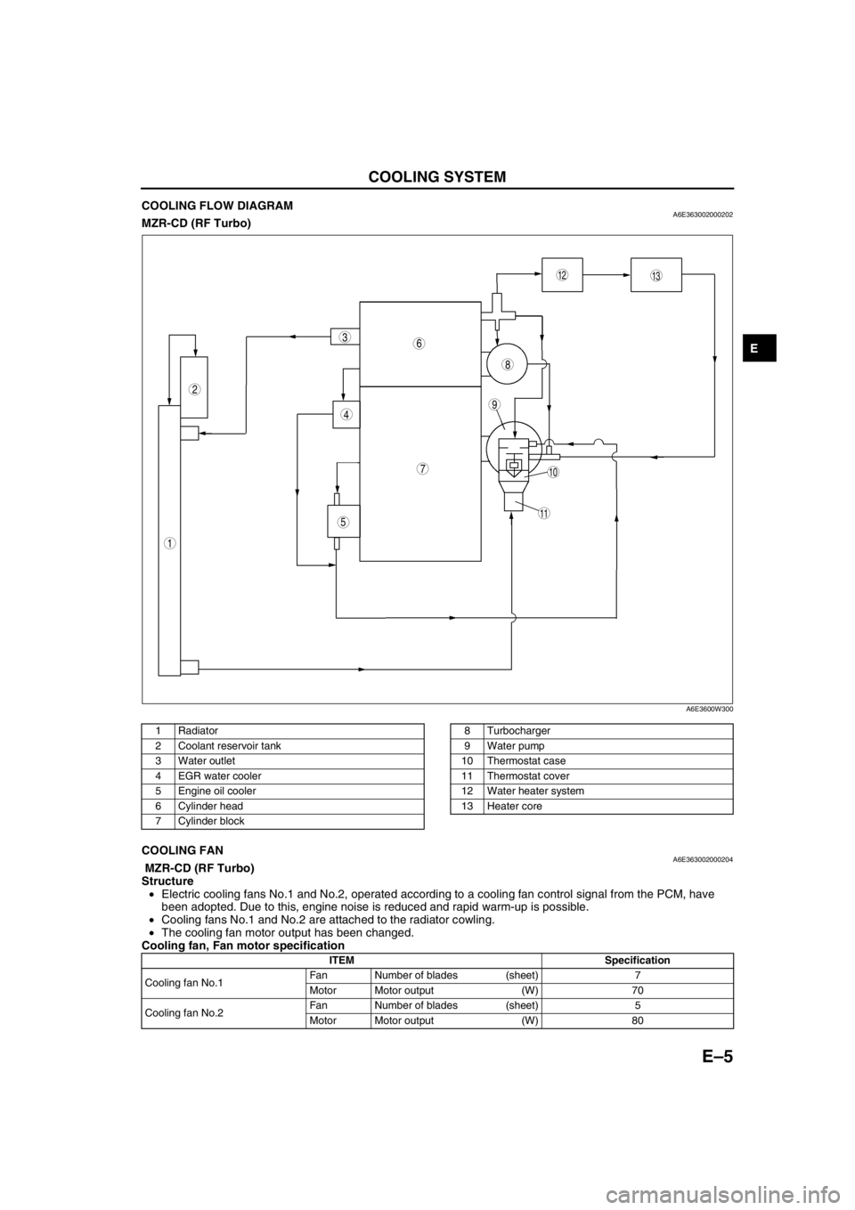
COOLING FLOW DIAGRAMA6E363002000202MZR-CD (RF Turbo)
.
End Of SieCOOLING FANA6E363002000204 MZR-CD (RF Turbo)
Structure
•Electric cooling fans No.1 and No.2, operated according to a cooling fan control signal from the PCM, have
been adopted. Due to this, engine noise is reduced and rapid warm-up is possible.
•Cooling fans No.1 and No.2 are attached to the radiator cowling.
•The cooling fan motor output has been changed.
Cooling fan, Fan motor specification
End Of Sie
9
8
7
5
4
3
1
2
10
13
11
12
6
A6E3600W300
1Radiator
2 Coolant reservoir tank
3 Water outlet
4EGR water cooler
5 Engine oil cooler
6 Cylinder head
7 Cylinder block8 Turbocharger
9 Water pump
10 Thermostat case
11 Thermostat cover
12 Water heater system
13 Heater core
ITEM Specification
Cooling fan No.1Fan Number of blades (sheet) 7
Motor Motor output (W) 70
Cooling fan No.2Fan Number of blades (sheet) 5
Motor Motor output (W) 80
Page 82 of 909
RADIATOR CAP
E–7
E
RADIATOR CAP INSPECTIONA6E361415201201MZR-CD (RF Turbo)
Warning
•Never remove the radiator cap while the engine is running, or when the engine and radiator are
hot. Scalding coolant and steam may shoot out and cause serious injury. It may also damage the
engine and cooling system.
•Turn off the engine and wait until it is cool. Even then, be very careful when removing the cap.
Wrap a thick cloth around it and slowly turn it counterclockwise to the first stop. Step back while
the pressure escapes.
•When you are sure all the pressure is gone, press down on the cap using the cloth, turn it, and
remove it.
1. Clean the radiator cap negative pressure valve and the sealed part.
2. Inspect the crack or turn over on the sealed part of the radiator cap.
•If not as specified, repace the radiator cap.
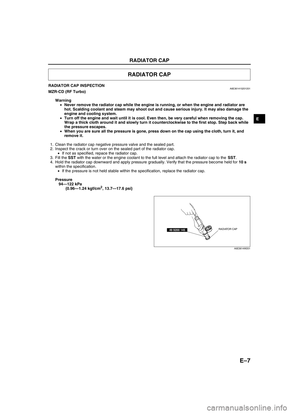
3. Fill the SST with the water or the engine coolant to the full level and attach the radiator cap to the SST.
4. Hold the radiator cap downward and apply pressure gradually. Verify that the pressure become held for 10 s
within the specification.
•If the pressure is not held stable within the specification, replace the radiator cap.
Pressure
94—122 kPa
{0.96—1.24 kgf/cm
2, 13.7—17.6 psi}
End Of Sie
RADIATOR CAP
RADIATOR CAP49 9200 145
A6E3614W201
Page 83 of 909
E–8
ENGINE COOLANT
ENGINE COOLANT LEAKAGE INSPECTIONA6E361215201201MZR-CD (RF Turbo)
Warning
•Never remove the radiator cap while the engine is running, or when the engine and radiator are
hot. Scalding coolant and steam may shoot out and cause serious injury. It may also damage the
engine and cooling system.
•Turn off the engine and wait until it is cool. Even then, be very careful when removing the cap.
Wrap a thick cloth around it and slowly turn it counterclockwise to the first stop. Step back while
the pressure escapes.
•When you are sure all the pressure is gone, press down on the cap using the cloth, turn it, and
remove it.
1. Inspect the coolant level.
2. Remove the radiator cap.
3. Clean the mounting surface of the rediator cap and the upper radiator hose.
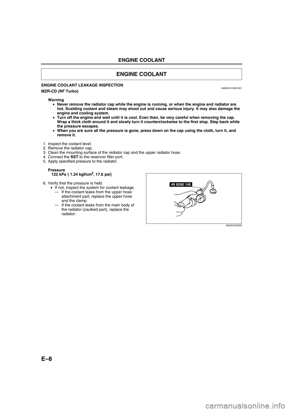
4. Connect the SST to the reservoir filler port.
5. Apply specified pressure to the radiator.
Pressure
122 kPa { 1.24 kgf/cm
2, 17.6 psi}
6. Verify that the pressure is held.
•If not, inspect the system for coolant leakage.
—If the coolant leaks from the upper hose
attachment part, replace the upper hose
and the clamp.
—If the coolant leaks from the main body of
the radiator (caulked part), replace the
radiator.
End Of Sie
ENGINE COOLANT
49 9200 145
A6E3612W200
Page 89 of 909
![MAZDA 6 2002 Suplement User Guide F1–1
F1
F1FUEL AND EMISSION CONTROL SYSTEM
[L8, LF, L3]
OUTLINE.............................................................. F1-2
OUTLINE OF CONSTRUCTION ....................... F1-2
FEATURES ..... MAZDA 6 2002 Suplement User Guide F1–1
F1
F1FUEL AND EMISSION CONTROL SYSTEM
[L8, LF, L3]
OUTLINE.............................................................. F1-2
OUTLINE OF CONSTRUCTION ....................... F1-2
FEATURES .....](/img/28/57057/w960_57057-88.png)
F1–1
F1
F1FUEL AND EMISSION CONTROL SYSTEM
[L8, LF, L3]
OUTLINE.............................................................. F1-2
OUTLINE OF CONSTRUCTION ....................... F1-2
FEATURES ........................................................ F1-2
SPECIFICATIONS ............................................. F1-2
CONTROL SYSTEM DIAGRAM (4WD)............. F1-3
CONTROL SYSTEM WIRING DIAGRAM
(4WD).............................................................. F1-4
FUEL SYSTEM..................................................... F1-9
OUTLINE ........................................................... F1-9
STRUCTURAL VIEW......................................... F1-9
SYSTEM DIAGRAM ........................................ F1-10
FUEL PUMP (TRANSFER).............................. F1-10
QUICK RELEASE CONNECTOR (FUEL TANK
SIDE, TRANSFER HOSE PART) ................. F1-12
EXHAUST SYSTEM........................................... F1-13
OUTLINE ......................................................... F1-13
STRUCTURAL VIEW....................................... F1-13
CONTROL SYSTEM........................................... F1-14
OUTLINE ......................................................... F1-14
STRUCTURAL VIEW (4WD) ........................... F1-16
BLOCK DIAGRAM ........................................... F1-17
CONTROL DEVICE AND CONTROL
RELATIONSHIP CHART .............................. F1-19
CONTROLLER AREA NETWORK (CAN) ....... F1-21
OUTLINE............................................................ F1-22
SUPPLEMENTAL SERVICE
INFORMATION ............................................. F1-22
ENGINE TUNE-UP............................................. F1-22
IDLE SPEED INSPECTION (4WD) ................. F1-22
FUEL SYSTEM................................................... F1-23
FUEL TANK REMOVAL/INSTALLATION ........ F1-23
FUEL PUMP UNIT
REMOVAL/INSTALLATION .......................... F1-26
FUEL HOSE (FUEL TANK SIDE,
TRANSFER HOSE PART)
REMOVAL/INSTALLATION .......................... F1-29
EXHAUST SYSTEM........................................... F1-30
EXHAUST SYSTEM
REMOVAL/INSTALLATION .......................... F1-30
CONTROL SYSTEM........................................... F1-33
PCM INSPECTION (4WD)............................... F1-33
ON-BOARD DIAGNOSTIC................................. F1-50
OUTLINE ......................................................... F1-50
CONTROL DEVICE AND MONITORING
SYSTEM RELATIONSHIP CHART .............. F1-50
DIAGNOSTIC TEST MODE (4WD) ................. F1-50
DTC (4WD) ...................................................... F1-52
OBD DRIVE MODE ......................................... F1-52
DTC TABLE ..................................................... F1-54
TROUBLESHOOTING........................................ F1-57ENGINE SYMPTOM
TROUBLESHOOTING .................................. F1-57
QUICK DIAGNOSTIC CHART ......................... F1-58
NO.14 POOR FUEL ECONOMY ..................... F1-62
NO.22 VIBRATION CONCERNS
(ENGINE) ...................................................... F1-64 FEATURES
SERVICE
Page 100 of 909

F1–12
FUEL SYSTEM
QUICK RELEASE CONNECTOR (FUEL TANK SIDE, TRANSFER HOSE PART)A6E391242692201Function
•The quick release connector makes disconnecting and connecting of fuel hoses and fuel pipes easy.
Structure
•The quick release connector is adopted for the transfer hose part of the fuel tank side.
•The quick release connector is composed of a retainer, O-ring and other parts. The quick release connector
and plastic fuel hose are integrated and cannot be disconnected.
•The retainer and quick release connector are integrated and cannot be disconnected.
•An SST is not required to uncouple this type of quick release connector.
.
Operation
•Squeeze the tabs of the retainer to unlock and disconnect the quick release connector from the fuel pipe.
•A click is heard when the tabs of the retainer are pushed correctly into the lock point of the quick release
connector.
.
End Of Sie
3
1
2
A6E39122010
1Tab
2 Quick release connector3 Disconnect
7
5
4
3
6
1
21
A6E39122011
1 O-ring
2 Lock point
3 Disconnect
4Fuel hose5 Quick release connector
6 Retainer
7 Fuel pipe