lock MAZDA 6 2002 Suplement Owner's Manual
[x] Cancel search | Manufacturer: MAZDA, Model Year: 2002, Model line: 6, Model: MAZDA 6 2002Pages: 909, PDF Size: 17.16 MB
Page 105 of 909

CONTROL SYSTEM
F1–17
F1
BLOCK DIAGRAMA6E394018880203
.
1
2
3
4
5
6
7
8
9
10
11
12
13
14
15
16
17
1832
31
30
29
28
27
26
25
24
23
22
21
20
1933
34
35
36
37
38
39
40
41
42
43
44
45
46
A6E3940T001
Page 115 of 909

FUEL SYSTEM
F1–27
F1
Plastic Fuel Hose Removal Note
Caution
•The quick release connector may be damaged if the tab is bent excessively. Do not expand the tab
over the stopper.
1. Disconnect the quick release connector.
(1) Push the tab on the locking coupler 90
degrees until it stops.
(2) Pull the fuel hose straight back.
Note
•The stopper may be removed from the quick
connector. Take care not to lose it.
Reinstall it to the quick release connector
before reconnecting the fuel line.
•The locking coupler has two internal locking
tabs which retain the fuel pipe. Be sure that
the tab on the locking coupler is rotated until
it stops to release two internal locking tabs.
2. Cover the disconnected quick release connector
and fuel pipe with vinyl sheets or the like to
prevent them from being scratched or
contaminated with foreign material.
Fuel Pump Cap Removal Note
1. Using the SST, remove the fuel pump cap.
FUEL PIPE
STOPPER TAB
A6E3912W001
LOCKING TAB
A6E3912W002
A6E39122015
49 T042 001A
A6E39122012
Page 120 of 909

F1–32
EXHAUST SYSTEM
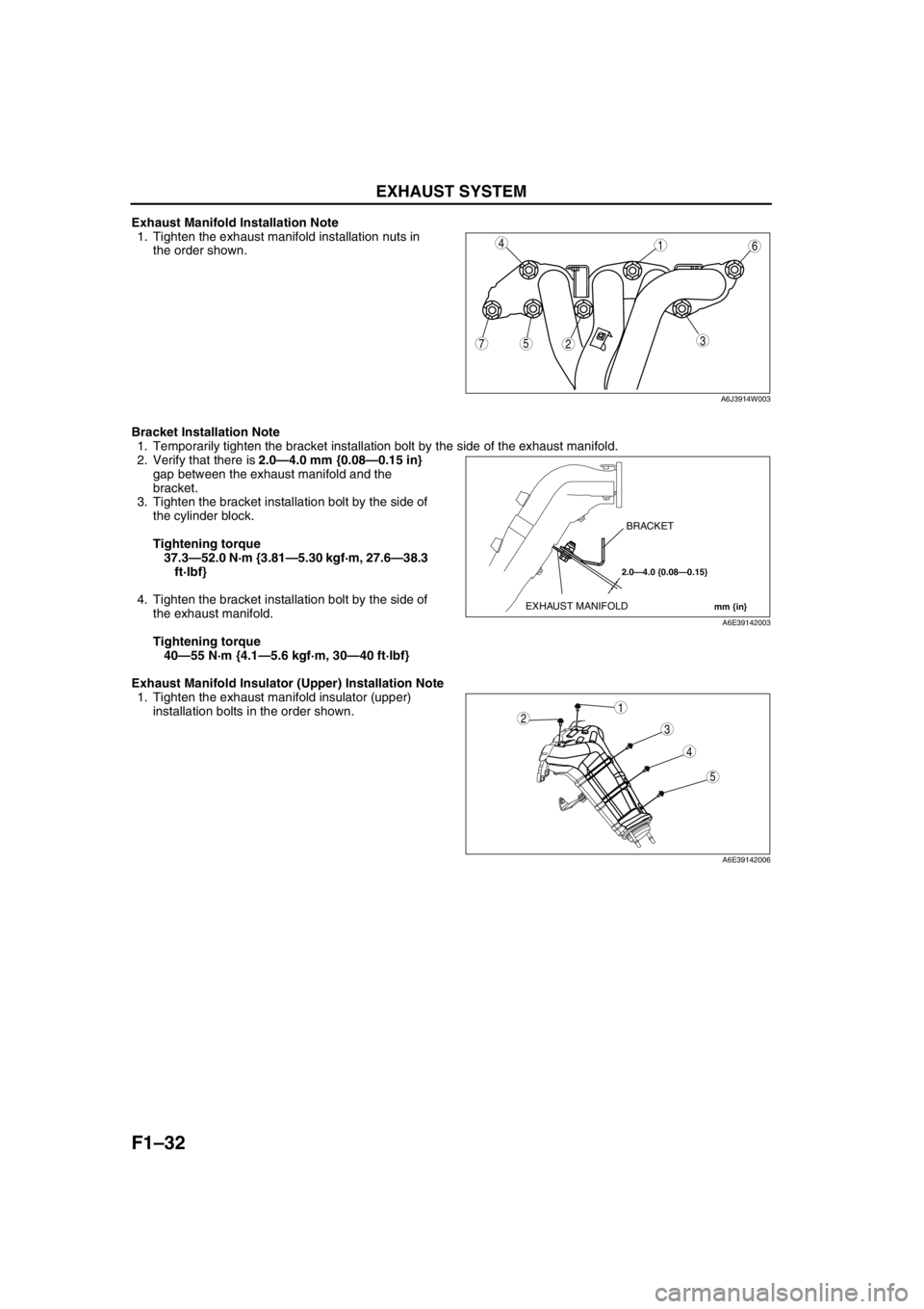
Exhaust Manifold Installation Note
1. Tighten the exhaust manifold installation nuts in
the order shown.
Bracket Installation Note
1. Temporarily tighten the bracket installation bolt by the side of the exhaust manifold.
2. Verify that there is 2.0—4.0 mm {0.08—0.15 in}
gap between the exhaust manifold and the
bracket.
3. Tighten the bracket installation bolt by the side of
the cylinder block.
Tightening torque
37.3—52.0 N·m {3.81—5.30 kgf·m, 27.6—38.3
ft·lbf}
4. Tighten the bracket installation bolt by the side of
the exhaust manifold.
Tightening torque
40—55 N·m {4.1—5.6 kgf·m, 30—40 ft·lbf}
Exhaust Manifold Insulator (Upper) Installation Note
1. Tighten the exhaust manifold insulator (upper)
installation bolts in the order shown.
End Of Sie
75
4
3
1
2
6
A6J3914W003
2.0—4.0 {0.08—0.15}
mm {in}EXHAUST MANIFOLDBRACKET
A6E39142003
5
4
3
12
A6E39142006
Page 146 of 909

F1–58
TROUBLESHOOTING
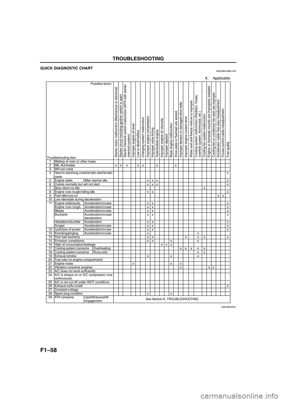
QUICK DIAGNOSTIC CHARTA6E398018881202
X: Applicable
Possible factor
Troubleshooting item
Starter motor malfunction (Mechanical or electrical)
Starter circuit including ignition switch is open.
Starter interlock switch malfunction (MTX with starter
interlock system)
Improper engine oil level
Low or dead battery
Charging system malfunction
Improper engine compression
Improper valve timing
Hydrolocked engine
Improper engine oil viscosity
Improper dipstick
Base engine malfunction
Drive plate or flywheel are seized.
Improper tension or damaged drive belts
Improper engine coolant level
Water and anti-freeze mixture is improper.
Cooling system malfunction (Radiator, hoses,
overflow system, thermostat, etc.)
Cooling fan system malfunction
Engine or transaxle mounts are improperly installed.
Cooling fan or condenser fan seat are improper.
Accelerator cable free play misadjustment
Cruise control cable misadjustment
Fuel quality
1 Melting of main or other fuses2 MIL illuminates x x x x x x x3 Will not crank4 Hard to start/long crank/erratic start/erratic
crankx
5 Engine stalls. After start/at idle x x x x6 Cranks normally but will not start x x x x7 Slow return to idlex8 Engine runs rough/rolling idle x x x9 Fast idle/runs onxx10 Low idle/stalls during decelerationEngine stalls/quits. Acceleration/cruise x x xEngine runs rough. Acceleration/cruise x x xMissesAcceleration/cruise x x xBuck/jerk Acceleration/cruise/
decelerationxx x
Hesitation/stumble Acceleration x x x
11
Surges Acceleration/cruis
exx x12 Lack/loss of powerAcceleration/cruisexx x13 Knocking/pingingAcceleration/cruisexx14 Poor fuel economy x x x x x x15 Emission compliance x x x x16 High oil consumption/leakage x x x17 Cooling system concerns Overheatingxx x x x18 Cooling system concernsRuns cold x x19 Exhaust smoke x x x20 Fuel odor (in engine compartment)21 Engine noise x x x22 Vibration concerns (engine) x x x23 A/C does not work sufficiently.24 A/C is always on or A/C compressor runs
continuously.
25 A/C is not cut off under WOT conditions.26 Exhaust sulfur smellx27 Constant voltage28 Spark plug condition x x29 ATX concernsUpshift/downshift
engagementSee Section K, TROUBLESHOOTING
A6E39802001
Page 153 of 909
![MAZDA 6 2002 Suplement Owners Manual F2–1
F2
F2FUEL AND EMISSION CONTROL SYSTEMS
[MZR-CD (RF Turbo)]
OUTLINE.............................................................. F2-3
OUTLINE OF CONSTRUCTION ....................... F2-3
FEATUR MAZDA 6 2002 Suplement Owners Manual F2–1
F2
F2FUEL AND EMISSION CONTROL SYSTEMS
[MZR-CD (RF Turbo)]
OUTLINE.............................................................. F2-3
OUTLINE OF CONSTRUCTION ....................... F2-3
FEATUR](/img/28/57057/w960_57057-152.png)
F2–1
F2
F2FUEL AND EMISSION CONTROL SYSTEMS
[MZR-CD (RF Turbo)]
OUTLINE.............................................................. F2-3
OUTLINE OF CONSTRUCTION ....................... F2-3
FEATURES ........................................................ F2-3
SPECIFICATIONS ............................................. F2-3
CONTROL SYSTEM DIAGRAM ........................ F2-4
CONTROL SYSTEM WIRING DIAGRAM.......... F2-5
INTAKE-AIR SYSTEM.......................................... F2-8
OUTLINE ........................................................... F2-8
STRUCTURAL VIEW......................................... F2-9
FUEL SYSTEM................................................... F2-10
OUTLINE ......................................................... F2-10
STRUCTURAL VIEW....................................... F2-11
EXHAUST SYSTEM........................................... F2-13
OUTLINE ......................................................... F2-13
STRUCTURAL VIEW....................................... F2-13
EMISSION SYSTEM........................................... F2-14
OUTLINE ......................................................... F2-14
STRUCTURAL VIEW....................................... F2-15
WARM UP OXIDATION CATALYTIC
CONVERTER DESCRIPTION ...................... F2-16
CONTROL SYSTEM........................................... F2-16
OUTLINE ......................................................... F2-16
STRUCTURAL VIEW....................................... F2-18
BLOCK DIAGRAM ........................................... F2-20
CONTROL DEVICE AND CONTROL
RELATIONSHIP CHART .............................. F2-22
CRUISE CONTROL SYSTEM ......................... F2-23
CONTROLLER AREA NETWORK (CAN) ....... F2-24
ON-BOARD DIAGNOSTIC................................. F2-24
OUTLINE ......................................................... F2-24
DTC.................................................................. F2-24
KOEO/KOER SELF-TEST ............................... F2-26
PID/DATA MONITOR AND RECORD ............. F2-27
SIMULATION TEST ......................................... F2-27
LOCATION INDEX............................................. F2-28
INTAKE-AIR SYSTEM ..................................... F2-28
FUEL SYSTEM ................................................ F2-29
EMISSION SYSTEM........................................ F2-31
CONTROL SYSTEM........................................ F2-32
ENGINE TUNE-UP............................................. F2-34
ENGINE TUNE-UP PREPARATION ............... F2-34
IDLE SPEED INSPECTION ............................. F2-34
CORRECTION PROCEDURE ......................... F2-34
INTAKE-AIR SYSTEM........................................ F2-35
VACUUM TUBE ROUTING DIAGRAM............ F2-35
INTAKE-AIR SYSTEM
REMOVAL/INSTALLATION .......................... F2-36
AIR CLEANER ELEMENT INSPECTION ........ F2-37
TURBOCHARGER INSPECTION ................... F2-38
GUIDE BLADE ACTUATOR INSPECTION ..... F2-39
VARIABLE BOOST CONTROL (VBC)
SOLENOID VALVE INSPECTION ................ F2-40VARIABLE BOOST CONTROL (VBC)
CHECK VALVE INSPECTION ...................... F2-41
VARIABLE SWIRL CONTROL (VSC)
VALVE ACTUATOR INSPECTION ............... F2-41
VARIABLE SWIRL CONTROL (VSC)
SOLENOID VALVE INSPECTION ................ F2-42
GLOW PLUG REMOVAL/INSTALLATION ...... F2-42
GLOW PLUG INSPECTION ............................ F2-43
GLOW PLUG LEAD INSPECTION .................. F2-43
ACCELERATOR PEDAL COMPONENT
REMOVAL/INSTALLATION .......................... F2-44
ACCELERATOR PEDAL COMPONENT
DISASSEMBLY/ASSEMBLY ........................ F2-44
FUEL SYSTEM................................................... F2-45
BEFORE REPAIR PROCEDURE .................... F2-45
AFTER REPAIR PROCEDURE ....................... F2-45
FUEL TANK REMOVAL/INSTALLATION ........ F2-45
FUEL TANK INSPECTION .............................. F2-49
NONRETURN VALVE INSPECTION............... F2-50
FUEL FILTER COMPONENT
REMOVAL/INSTALLATION .......................... F2-50
FUEL FILTER COMPONENT
DISASSEMBLY/ASSEMBLY ........................ F2-51
FUEL WARMER INSPECTION........................ F2-51
SEDIMENTOR WATER DRAINING................. F2-52
SEDIMENTOR SWITCH INSPECTION ........... F2-52
SUPPLY PUMP REMOVAL/INSTALLATION .. F2-53
SUPPLY PUMP INSPECTION......................... F2-54
SUCTION CONTROL VALVE INSPECTION ... F2-54
COMMON RAIL INSPECTION ........................ F2-54
FUEL INJECTOR REMOVAL/INSTALLATION F2-55
FUEL INJECTOR INSPECTION ...................... F2-56
EXHAUST SYSTEM........................................... F2-57
EXHAUST SYSTEM INSPECTION ................. F2-57
EXHAUST SYSTEM
REMOVAL/INSTALLATION .......................... F2-57
EMISSION SYSTEM........................................... F2-59
EGR VALVE REMOVAL/INSTALLATION........ F2-59
EGR VALVE INSPECTION .............................. F2-59
EGR SOLENOID VALVE (VACUUM)
INSPECTION ................................................ F2-60
EGR SOLENOID VALVE (VENT)
INSPECTION ................................................ F2-60
EGR CONTROL SOLENOID VALVE
INSPECTION ................................................ F2-61
INTAKE SHUTTER VALVE ACTUATOR
INSPECTION ................................................ F2-62
INTAKE SHUTTER SOLENOID VALVE
INSPECTION ................................................ F2-63
CONTROL SYSTEM........................................... F2-64
PCM REMOVAL/INSTALLATION .................... F2-64
PCM INSPECTION .......................................... F2-65
PCM CONFIGURATION .................................. F2-68
CLUTCH SWITCH INSPECTION .................... F2-68
NEUTRAL SWITCH INSPECTION .................. F2-69
IDLE SWITCH INSPECTION ........................... F2-70
IDLE SWITCH ADJUSTMENT ......................... F2-71
ACCELERATOR POSITION SENSOR
INSPECTION ................................................ F2-72
ACCELERATOR POSITION SENSOR
ADJUSTMENT .............................................. F2-73 FEATURES
SERVICE
Page 157 of 909

OUTLINE
F2–5
F2
CONTROL SYSTEM WIRING DIAGRAMA6E400218881205
BA
ABA
ABA
ABA
A1A
1B 1C 1D 1E 1F1G
1H2A
2B 2C2D
2E
2F2G 2H
a
b
c
d
e
f
g
30 42
44 4543 1A
1B 1C 1D 1E 1F
13 39
80
28 78
A 57
E5633 1
427 73464
1041038565 9169
E53
79 9
1460
CBD AE C
A
Dh
i
j
k
l
m
n
o C
D
LOCKACCONSTB
ACCIG2IG1ST
AA
M
BA
A
AAB
9
8
7
5
4
3
10
19
18
17
1516
14
131112
20
6
1
2
23
21
22
A6E40022002
Page 172 of 909

F2–20
CONTROL SYSTEM
BLOCK DIAGRAMA6E404018881203
.
CRUISE
MAIN
CRUISE
9
8
7
5
4
3
10
6
1
2
14
13
11
12
19
18
17
15
16
20
29
28
27
25
26
24
23
21
22
30
37
35
36
33
31
32
34
39
38
40
49
48
47
45
46
44
43
41
42
50
51
52
53
A6E40402017
Page 199 of 909

FUEL SYSTEM
F2–47
F2
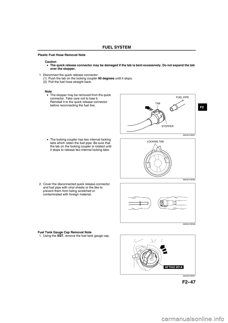
Plastic Fuel Hose Removal Note
Caution
•The quick release connector may be damaged if the tab is bent excessively. Do not expand the tab
over the stopper.
1. Disconnect the quick release connector.
(1) Push the tab on the locking coupler 90 degrees until it stops.
(2) Pull the fuel hose straight back.
Note
•The stopper may be removed from the quick
connector. Take care not to lose it.
Reinstall it to the quick release connector
before reconnecting the fuel line.
•The locking coupler has two internal locking
tabs which retain the fuel pipe. Be sure that
the tab on the locking coupler is rotated until
it stops to release two internal locking tabs.
2. Cover the disconnected quick release connector
and fuel pipe with vinyl sheets or the like to
prevent them from being scratched or
contaminated with foreign material.
Fuel Tank Gauge Cap Removal Note
1. Using the SST, remove the fuel tank gauge cap.
FUEL PIPE
STOPPER TAB
A6E3912W001
LOCKING TAB
A6E3912W002
A6E3912W039
49 T042 001A
A6A3912W007
Page 223 of 909

CONTROL SYSTEM
F2–71
F2
IDLE SWITCH ADJUSTMENTA6E404041600202
Caution
•Adjusting the idle switch unnecessarily may adversely affect engine control. Therefore, adjust the
idle switch only when it is replaced.
1. Verify that the accelerator position sensor is normal.
2. Visually inspect all accelerator pedal components for looseness.
3. Loosen the locknut that secures the idle switch.
4. Verify that the power circuit voltage.
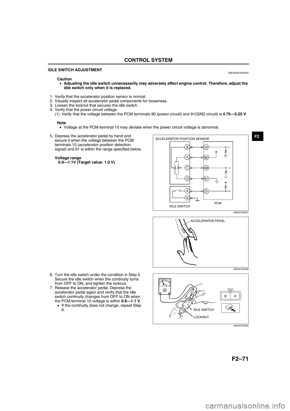
(1) Verify that the voltage between the PCM terminals 90 (power circuit) and 91(GND circuit) is 4.75—5.25 V.
Note
•Voltage at the PCM terminal 10 may deviate when the power circuit voltage is abnormal.
5. Depress the accelerator pedal by hand and
secure it when the voltage between the PCM
terminals 10 (accelerator position detection
signal) and 91 is within the range specified below.
Voltage range
0.9—1.1V (Target value: 1.0 V)
6. Turn the idle switch under the condition in Step 5.
Secure the idle switch when the continuity turns
from OFF to ON, and tighten the locknut.
7. Release the accelerator pedal. Depress the
accelerator pedal again and verify that the idle
switch continuity changes from OFF to ON when
the PCM terminal 10 voltage is within 0.9—1.1 V.
•If the continuity does not change, repeat Step
6.
End Of Sie
ACCELERATOR POSITION SENSOR
IDLE SWITCHPCM B
A
C
D
A
B31 10
90
88
91
A6E40702037
ACCELERATOR PEDAL
A6E40702039
IDLE SWITCH
LOCKNUTA
B
A6E40702040
Page 319 of 909

TROUBLESHOOTING
F2–167
F2
SYMPTOM QUICK DIAGNOSIS CHARTA6E408018881202
×: Applicable
Troubleshooting item
1 Melting of main or other fuses
2 MIL illuminates
3 Will not crank×× ×× × ×
4 Hard start/long crank/erratic start/erratic crank×× ×
5 Engine stalls After start/at idle××
6 Cranks normally but will not start××
7 Slow return to idle
8 Engine runs rough/rolling idle××
9 Fast idle/runs on
10 Low idle/stalls during deceleration××
11Engine stalls/quits Acceleration/cruise××
Engine runs rough Acceleration/cruise××
Misses Acceleration/cruise××
Buck/jerk Acceleration/cruise/ deceleration××
Hesitation/stumble Acceleration××
Surges Acceleration/cruise××
12 Lack/loss of power Acceleration/cruise××
13 Knocking/pinging××
14 Poor fuel economy××
15 Emissions compliance×× ×
16 High oil consumption/leakage××××
17 Cooling system concerns Overheating××
18 Cooling system concerns Runs cold
19 Excessive black smoke×
20 Fuel odor (in engine compartment)
21 Engine noise×× × ×
22 Vibration concerns (engine)×
23 A/C does not work sufficiently
24 A/C always on or A/C compressor runs continuously
25 A/C does not cut off under wide open throttle conditions
26 Constant voltage
Starter motor malfunction (Mechanical or electrical)Starter circuit including engine switch is openImproper engine oil levelLow or dead bateryCharging system malfunctionLow engine compressionImproper valve timingHydrolocked egineImproper engine oil viscosityImproper dipstickBase engine malfunctionSeized flywheelImproper tension or damaged drivebelts