lock MAZDA 6 2002 Suplement Repair Manual
[x] Cancel search | Manufacturer: MAZDA, Model Year: 2002, Model line: 6, Model: MAZDA 6 2002Pages: 909, PDF Size: 17.16 MB
Page 480 of 909

AUTOMATIC TRANSAXLE
K2–65
K2
Memory Function
•The memory function stores failure information detected in the failure detection function. Once failure
information is stored, the memory will not be cleared even when the ignition switch is turned off (LOCK
position) or the malfunction is repaired.
•The stored memory (failure information) can be cleared by using the WDS or disconnecting the negative
battery cable.
Failure Indication Function
•The failure indication function illuminates the AT warning lights when the failure detection function determines
there is a malfunction.
DTC Table
X : Available
CCM:Continuous monitor
Fail-safe Function
•In the fail-safe function, minimum vehicle drivability is obtained by changing the signals that are determined as
malfunctions by the failure detection function to the preset values, and limiting the TCM control.
DTC No. On-board diagnostic function MILAT warning
light
indicationDCMonitor
itemMemory
function
P0705 TR switch circuit malfunction (Power short circuit) X X 2 CCM X
P0706 TR switch circuit malfunction (Open/ground short circuit) X X 2 CCM X
P0711 TFT sensor malfunction (Stuck) X–2 CCM X
P0712 TFT sensor circuit malfunction (Short circuit) X X 2 CCM X
P0713 TFT sensor circuit malfunction (Open circuit) X X 2 CCM X
P0715 Input/turbine speed sensor circuit malfunction X X 2 CCM X
P0720 Vehicle speedometer sensor circuit malfunction X X 2 CCM X
P0740 TCC system X–2 CCM X
P0743 TCC solenoid valve malfunction (Open/short) X X 1 CCM X
P0748 Pressure control solenoid malfunction (Open/short)–X–CCM X
P0751 Shift solenoid A malfunction (Stuck off) X–2 CCM X
P0752 Shift solenoid A malfunction (Stuck on) X–2 CCM X
P0753 Shift solenoid A malfunction (Open/short) X X 1 CCM X
P0756 Shift solenoid B malfunction (Stuck off) X–2 CCM X
P0757 Shift solenoid B malfunction (Stuck on) X–2 CCM X
P0758 Shift solenoid B malfunction (Open/short) X X 1 CCM X
P0761 Shift solenoid C malfunction (Stuck off) X–2 CCM X
P0762 Shift solenoid C malfunction (Stuck on) X–2 CCM X
P0763 Shift solenoid C malfunction (Open/short) X X 1 CCM X
P0768 Reduction timing solenoid malfunction (Open/short)–X–CCM X
P0773 Neutral shift solenoid malfunction (Open/short)–X–CCM X
P0778 2-4 brake solenoid malfunction (Open/short)–X–CCM X
P0791 Intermediate sensor malfunction (Open/short) X X 2 CCM X
P0798 High clutch solenoid malfunction (Open/short)–X–CCM X
P1710 GND return malfunction–––Other X
U0073 CAN BUS OFF X X 1 CCM X
U0100 TCM cannot receive any signals from PCM X X 1 CCM X
DTC
No.On-board diagnostic function Detection condition Fail-safe TCC
P0705Transaxle range (TR) switch
circuit malfunction (power short
circuit)•Two or more range signals
are inputted from TR switch
for 5 seconds or more•TR switch priority
D > N > P > R
•Inhibits feedback control,
SLOPE mode, torque
reduction controlAvailable
P0706Transaxle range (TR) switch
circuit malfunction (open/ground
short circuit)•No range signal is inputted
from TR switch for 100
seconds or more•Inhibits feedback control,
SLOPE mode, torque
reduction controlAvailable
Page 510 of 909

AUTOMATIC TRANSAXLE
K2–95
K2
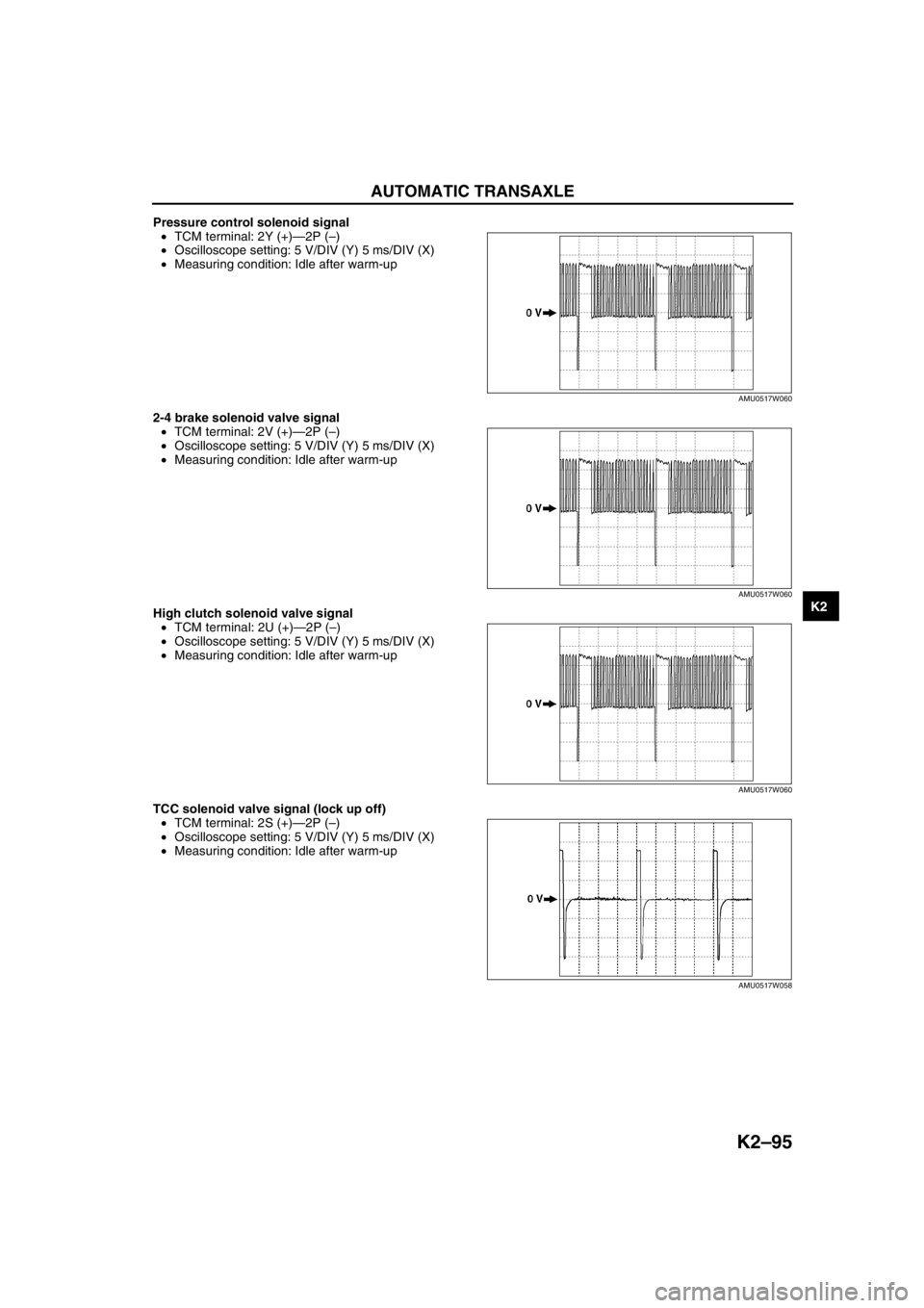
Pressure control solenoid signal
•TCM terminal: 2Y (+)—2P (–)
•Oscilloscope setting: 5 V/DIV (Y) 5 ms/DIV (X)
•Measuring condition: Idle after warm-up
2-4 brake solenoid valve signal
•TCM terminal: 2V (+)—2P (–)
•Oscilloscope setting: 5 V/DIV (Y) 5 ms/DIV (X)
•Measuring condition: Idle after warm-up
High clutch solenoid valve signal
•TCM terminal: 2U (+)—2P (–)
•Oscilloscope setting: 5 V/DIV (Y) 5 ms/DIV (X)
•Measuring condition: Idle after warm-up
TCC solenoid valve signal (lock up off)
•TCM terminal: 2S (+)—2P (–)
•Oscilloscope setting: 5 V/DIV (Y) 5 ms/DIV (X)
•Measuring condition: Idle after warm-up
AMU0517W060
AMU0517W060
AMU0517W060
AMU0517W058
Page 511 of 909

K2–96
AUTOMATIC TRANSAXLE
TCC solenoid valve signal (lock up on)
•TCM terminal: 2S (+)—2P (–)
•Oscilloscope setting: 5 V/DIV (Y) 5 ms/DIV (X)
•Measuring condition: Drive the vehicle with lock
up
End Of SieTCM REMOVAL/INSTALLATIONA6E5714189012121. Disconnect the negative battery cable.
2. For R.H.D., perform the following procedures.
(1) Remove the front side trim (left-side).
(2) Partially peel back the flower covering.
3. Remove in the order indicated in the table.
4. Install in the reverse order of removal.
U.K. specs.
.
AMU0517W059
2
1
3
SET BOLT
7.8—10.8
{80—110 kgf·cm,
69.5—95.4 in·lbf}
SET NUT
A6E5714W123
1 Control unit bracket
2 TCM connector3TCM
Page 526 of 909

AUTOMATIC TRANSAXLE
K2–111
K2
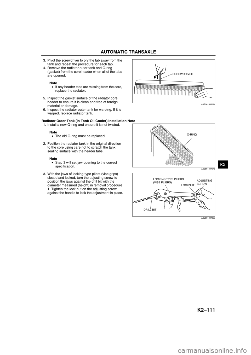
3. Pivot the screwdriver to pry the tab away from the
tank and repeat the procedure for each tab.
4. Remove the radiator outer tank and O-ring
(gasket) from the core header when all of the tabs
are opened.
Note
•If any header tabs are missing from the core,
replace the radiator.
5. Inspect the gasket surface of the radiator core
header to ensure it is clean and free of foreign
material or damage.
6. Inspect the radiator outer tank for warping. If it is
warped, replace radiator tank.
Radiator Outer Tank (In Tank Oil Cooler) Installation Note
1. Install a new O-ring and ensure it is not twisted.
Note
•The old O-ring must be replaced.
2. Position the radiator tank in the original direction
to the core using care not to scratch the tank
sealing surface with the header tabs.
Note
•Step 3 will set jaw opening to the correct
specification.
3. With the jaws of locking-type pliers (vise grips)
closed and locked, turn the adjusting screw to
position the jaws against the drill bit with the
diameter measured (height) in removal procedure
1. Tighten the lock nut on the adjusting screw
against the handle to lock the adjustment in place.
SCREWDRIVER
A6E5614W074
O-RING
A6E5614W075
LOCKING TYPE PLIERS
(VISE PLIERS)
LOCKNUTADJUSTING
SCREW
DRILL BIT
A6E5614W093
Page 527 of 909

K2–112
AUTOMATIC TRANSAXLE
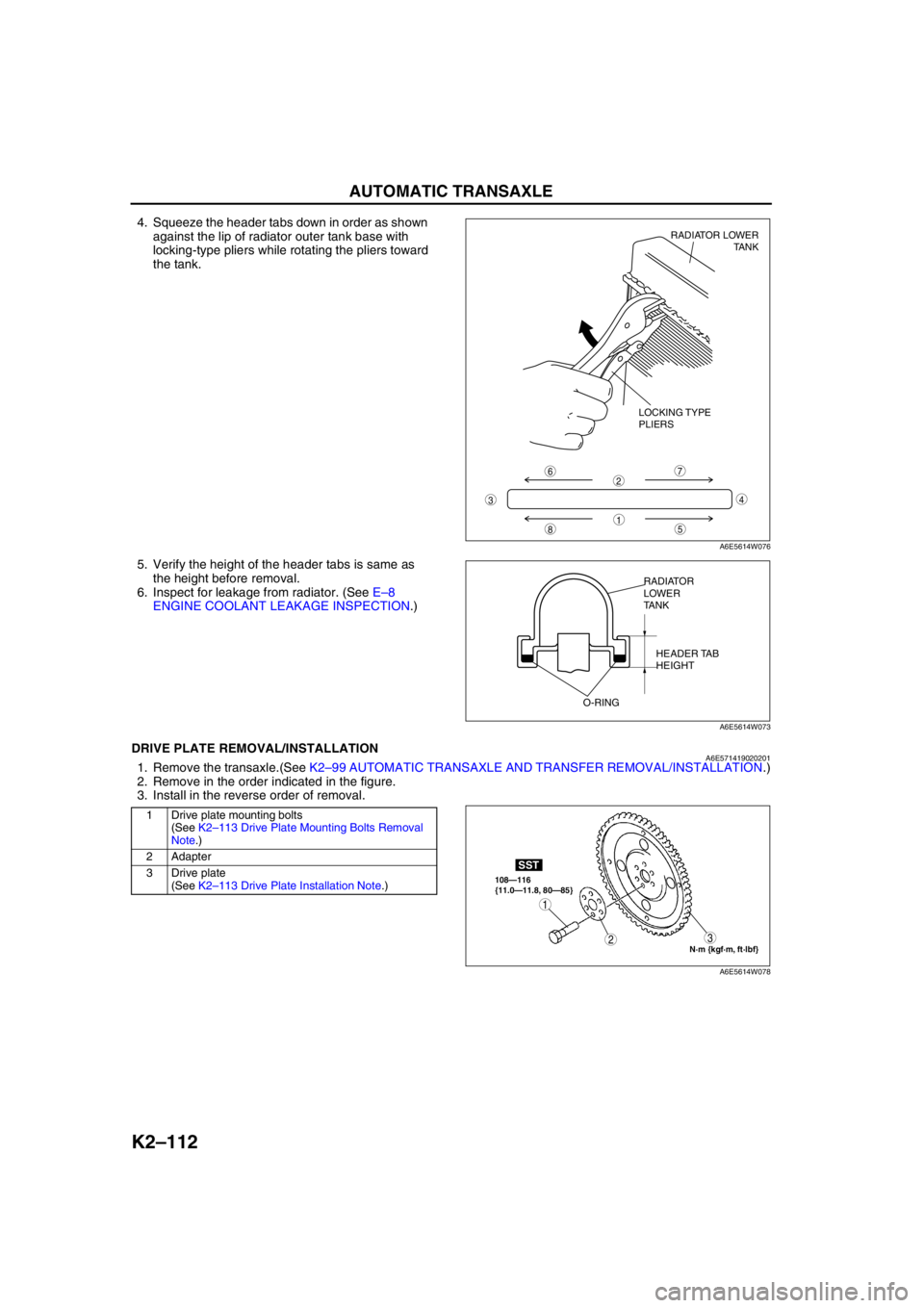
4. Squeeze the header tabs down in order as shown
against the lip of radiator outer tank base with
locking-type pliers while rotating the pliers toward
the tank.
5. Verify the height of the header tabs is same as
the height before removal.
6. Inspect for leakage from radiator. (See E–8
ENGINE COOLANT LEAKAGE INSPECTION.)
End Of SieDRIVE PLATE REMOVAL/INSTALLATIONA6E5714190202011. Remove the transaxle.(See K2–99 AUTOMATIC TRANSAXLE AND TRANSFER REMOVAL/INSTALLATION.)
2. Remove in the order indicated in the figure.
3. Install in the reverse order of removal.
.
8
7
5
43
6
1
2
LOCKING TYPE
PLIERSRADIATOR LOWER
TANK
A6E5614W076
RADIATOR
LOWER
TANK
HEADER TAB
HEIGHT
O-RING
A6E5614W073
1 Drive plate mounting bolts
(See K2–113 Drive Plate Mounting Bolts Removal
Note.)
2 Adapter
3 Drive plate
(See K2–113 Drive Plate Installation Note.)
N·m {kgf·m, ft·lbf} 108—116
{11.0—11.8, 80—85}
SST
3
1
2
A6E5614W078
Page 533 of 909

K2–118
AUTOMATIC TRANSAXLE SHIFT MECHANISM
SELECTOR CABLE ADJUSTMENTA6E5716465002011. Remove the center console.
2. Shift the selector lever to P position.
3. Unlock the lock piece of the selector cable
(selector lever side) in the order shown in the
figure.
4. Verify that the manual shaft is in P position.
5. Lock the lock piece of the selector cable (selector
lever side) in the order shown in the figure.
6. Install the center console.
7. Shift the selector lever from P position to M range,
and make sure that there are no other
components in that area to interfere with the lever.
End Of Sie
1
2
SAFETY
LOCK
LOCK PIECE
A6E5716W102
2
1
SAFETY
LOCK
LOCK PIECE
A6E5716W103
Page 535 of 909

K2–120
AUTOMATIC TRANSAXLE SHIFT MECHANISM
Selector Cable Removal Note
1. Remove the spring.
2. Remove the selector cable.
Selector Cable Installation Note
1. Install the selector cable to the selector lever certainly.
2. Install the selector cable to the bracket certainly.
Note
•Step 3, 4 is for the selector cable
replacement only.
3. Verify that the selector lever is in P position.
4. Lock the lock piece of the selector cable (selector
lever side) in the order shown in the figure.
5. Verify that the manual shaft is in P position.
SPRING SELECTOR CABLE
A6E5716W105
SELECTOR CABLE
A6E5616W020
2
1
SAFETY
LOCK
LOCK PIECE
A6E5716W103
DO NOT BEND
A6E5616W007
Page 598 of 909

TROUBLESHOOTING
K2–183
K2
AUTOMATIC TRANSAXLE SYMPTOM TROUBLESHOOTINGA6E578001030203Diagnostic Index
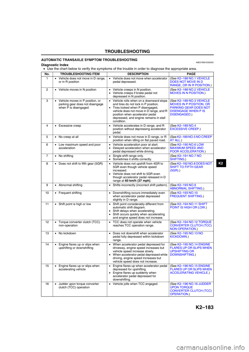
•Use the chart below to verify the symptoms of the trouble in order to diagnose the appropriate area.
No. TROUBLESHOOTING ITEM DESCRIPTION PAGE
1•Vehicle does not move in D range,
or in R position•Vehicle does not move when accelerator
pedal depressed.(See K2–188 NO.1 VEHICLE
DOES NOT MOVE IN D
RANGE, OR IN R POSITION.)
2•Vehicle moves in N position•Vehicle creeps in N position.
•Vehicle creeps if brake pedal not
depressed in N position.(See K2–188 NO.2 VEHICLE
MOVES IN N POSITION.)
3•Vehicle moves in P position, or
parking gear does not disengage
when P is disengaged•Vehicle rolls when on a downward slope
and tires do not lock in P position.
•Tires locked when P disengaged,
vehicle does not move in D range, and R
position when accelerator pedal
depressed, and engine remains in stall
condition.(See K2–189 NO.3 VEHICLE
MOVES IN P POSITION, OR
PARKING GEAR DOES NOT
DISENGAGE WHEN P IS
DISENGAGED.)
4•Excessive creep•Vehicle accelerates in D range, and R
position without depressing accelerator
pedal.(See K2–189 NO.4
EXCESSIVE CREEP.)
5•No creep at all•Vehicle does not move in D range, or R
position when idling on flat paved road.(See K2–189 NO.5 NO CREEP
AT ALL.)
6•Low maximum speed and poor
acceleration•Vehicle acceleration poor at start.
•Delayed acceleration when accelerator
pedal depressed while driving.(See K2–190 NO.6 LOW
MAXIMUM SPEED AND
POOR ACCELERATION.)
7•No shifting•Single shift range only.
•Sometimes it shifts correctly.(See K2–191 NO.7 NO
SHIFTING.)
8•Does not shift to fifth gear (5GR)•Vehicle does not upshift from 4GR to
5GR even though vehicle speed
increased.
•Vehicle does not shift to 5GR even
though accelerator pedal released in D
range at 60 km/h {37 mph}.(See K2–192 NO.8 DOES NOT
SHIFT TO FIFTH GEAR
(5GR).)
9•Abnormal shifting•Shifts incorrectly (incorrect shift pattern). (See K2–193 NO.9
ABNORMAL SHIFTING.)
10•Frequent shifting•Downshifting occurs immediately even
when accelerator pedal depressed
slightly in D range.(See K2–193 NO.10
FREQUENT SHIFTING.)
11•Shift point is high or low•Shift point considerably different from
automatic shift diagram.
•Shift delays when accelerating.
•Shift occurs quickly when accelerating
and engine speed does not increase.(See K2–194 NO.11 SHIFT
POINT IS HIGH OR LOW.)
12•Torque converter clutch (TCC)
non-operation•TCC does not operate when vehicle
reaches TCC operation range.(See K2–194 NO.12 TORQUE
CONVERTER CLUTCH (TCC)
NON-OPERATION.)
13•No kickdown•Does not downshift when accelerator
pedal fully depressed within kickdown
range.(See K2–195 NO.13 NO
KICKDOWN.)
14•Engine flares up or slips when
upshifting or downshifting•When accelerator pedal depressed for
driveway, engine speed increases but
vehicle speed increase slowly.
•When accelerator pedal depressed while
driving, engine speed increases but
vehicle speed does not increase.(See K2–195 NO.14 ENGINE
FLARES UP OR SLIPS WHEN
UPSHIFTING OR
DOWNSHIFTING.)
15•Engine flares up or slips when
accelerating vehicle•Engine flares up when accelerator pedal
depressed for upshifting.
•Engine flares up suddenly when
accelerator pedal depressed for
downshifting.(See K2–196 NO.15 ENGINE
FLARES UP OR SLIPS WHEN
ACCELERATING VEHICLE.)
16•Judder upon torque converter
clutch (TCC) operation•Vehicle jolts when TCC engaged. (See K2–196 NO.16 JUDDER
UPON TORQUE
CONVERTER CLUTCH (TCC)
OPERATION.)
Page 604 of 909

TROUBLESHOOTING
K2–189
K2
Diagnostic procedure
End Of SieNO.3 VEHICLE MOVES IN P POSITION, OR PARKING GEAR DOES NOT DISENGAGE WHEN P IS
DISENGAGED
A6E578001030206
End Of SieNO.4 EXCESSIVE CREEPA6E578001030207
End Of SieNO.5 NO CREEP AT ALLA6E578001030208
STEP INSPECTION ACTION
1•Does vehicle creep when selector lever
moved slightly in N position?Yes•Overhaul control valve body and repair or replace any
defective parts.
(See ATX Workshop Manual.)
—If problem remains, replace or overhaul transaxle and
repair or replace any defective parts.
(See K2–99 AUTOMATIC TRANSAXLE AND
TRANSFER REMOVAL/INSTALLATION.)
(See ATX Workshop Manual.)
No Inspect and adjust selector lever.
(See K2–117 SELECTOR LEVER INSPECTION.)
(See K2–118 SELECTOR CABLE ADJUSTMENT.)
2•Verify test results.
—If okay, return to diagnostic index to service any additional symptoms.
—If malfunction remains, inspect related Service Informations and perform repair or diagnosis.
—If vehicle repaired, troubleshooting completed.
—If vehicle not repaired or additional diagnostic information not available, replace TCM.
3 Vehicle moves in P position, or parking gear does not disengage when P is disengaged
DESCRIPTION•Vehicle rolls when on a downward slope and tires do not lock in P position.
•Tires locked when P disengaged, vehicle does not move in D range, and R position when accelerator
pedal depressed, and engine remains in stall condition.
POSSIBLE
CAUSE•Malfunction of parking mechanism (May have effect on noise or shock from transaxle)
•Improper adjustment of selector lever
•If vehicle moves in N position, perform symptom troubleshooting No.2 “Vehicle moves in N position”
Note
•Before following troubleshooting steps, make sure that Automatic Transaxle On-Board Diagnostic
and Automatic Transaxle Basic Inspection are conducted.
4 Excessive creep
DESCRIPTION•Vehicle accelerates in D range, and R position without depressing accelerator pedal.
POSSIBLE
CAUSE•Engine idle speed high (transaxle system is not cause of problem)
•Go to symptom troubleshooting No.9 “Fast idle/runs on”
(See Section F.)
Note
•Before following troubleshooting steps, make sure that Automatic Transaxle On-Board Diagnostic
and Automatic Transaxle Basic Inspection are conducted.
5 No creep at all
DESCRIPTION•Vehicle does not move in D range, or R position when idling on flat paved road.
POSSIBLE
CAUSE•Either engine output low or there is clutch circuit slippage.
—Clutch burned
•Line pressure low
•Malfunction of shift solenoid A, B, or C
•Malfunction of body ground
•Malfunction of control valve body
—Transaxle fixed in 4GR (Operation of fail-safe function)
•Short or open circuit in wiring
•Poor connection of connector
•Electronic parts of output and input system malfunctioning
—Engine torque is not start
•Malfunction of torque converter
Note
•Before following troubleshooting steps, make sure that Automatic Transaxle On-Board Diagnostic
and Automatic Transaxle Basic Inspection are conducted.
Page 624 of 909

L–8
PROPELLER SHAFT
.
SST
SST
SST
SST
SST
SST
R
SST
RR
R
R
R
R
R
R
SST
R
11
11
10
10
9
9
7
5
3
3
11
2
2
12
12
13
6
8
87157—177
{16.1—18.0,
116—130}
N·m {kgf·m, ft·lbf} 157—177
{16.1—18.0,
116—130}
R
R
3
1
2
4
R
A6E6110W003
1 Snap ring
(See L–9 Snap Ring Disassembly Note)
(See L–12 Bearing Cup and Snap Ring Assembly
Note)
2 Bearing cup
(See L–9 Bearing Cup Disassembly Note)
(See L–12 Bearing Cup and Snap Ring Assembly
Note)
3Spider
4 Flange yoke
5 Rear propeller shaft
6 Front propeller shaft
7 Locknut
(See L–9 Locknut Disassembly Note)
(See L–12 Locknut Assembly Note)
8 Spring washer9 Center yoke
(See L–10 Center Yoke Disassembly Note)
10 Bearing support
(See L–10 Bearing support Disassembly Note)
(See L–11 Bearing Support Assembly Note)
11 Dust cover
(See L–10 Dust Cover and Bearing Disassembly
Note)
(See L–11 Dust Cover Assembly Note)
12 Bearing
(See L–10 Dust Cover and Bearing Disassembly
Note)
(See L–11 Bearing Assembly Note)
13 Center propeller shaft