MAZDA 6 2002 Workshop Manual Suplement
Manufacturer: MAZDA, Model Year: 2002, Model line: 6, Model: MAZDA 6 2002Pages: 909, PDF Size: 17.16 MB
Page 221 of 909

CONTROL SYSTEM
F2–69
F2
NEUTRAL SWITCH INSPECTIONA6E404017640201
Note
•Perform the following test only when directed.
Continuity Inspection
1. Inspect for continuity between the neutral switch
terminals using an ohmmeter.
•If the neutral switch is okay, but the CPP/PNP
PID is out of specification, perform the “Circuit
Open/Short Inspection”
•If not as specified, replace the neutral switch.
Specification
Circuit Open/Short Inspection
1. Inspect for open/short circuit in the following wiring harnesses.
•If there is open/short circuit, repair or replace wiring harnesses.
Open circuit
•Signal circuit
—Neutral switch terminal A and PCM terminal 56
•GND circuit
—Neutral switch terminal B and GND
Short circuit
•Signal circuit
—Neutral switch terminal A and PCM terminal 56 to GND
End Of Sie
PUSH
RODB
A
A6E40702036
Condition
TransmissionTerminal
O
O: Continuity
A
B
Rod pushed
Except aboveIn neutral
Other
O
O
A6E40702035
Page 222 of 909

F2–70
CONTROL SYSTEM
IDLE SWITCH INSPECTIONA6E404041600201
Note
•Perform the following test only when directed.
1. Verify that the accelerator position sensor is normal.
2. Visually inspect all accelerator pedal components for looseness.
3. Verify that the idle switch is installed to the accelerator pedal properly.
4. Verify that the power circuit voltage.
(1) Verify that the voltage between the PCM terminals 90 (power circuit) and 91(GND circuit) is 4.75—5.25 V.
Note
•Voltage at the PCM terminal 10 may deviate when the power circuit voltage is abnormal.
5. Verify that the voltage at the PCM terminal 31
(idle signal) is 1 V or less with the accelerator
pedal fully released.
6. Depress the accelerator pedal gradually and hold
the pedal when the PCM terminal 31 voltage
changes to approximately 10 V.
7. Verify that the voltage between the PCM
terminals 10 (accelerator position detection
signal) and 91 is within the specification.
•If the circuit is okay, replace the idle switch.
Specification
0.85—1.15 V (Target value: 1.0 V)
Circuit Open/Short Inspection
1. Inspect for open/short circuit in the following
wiring harnesses.
•If there is open/short circuit, repair or replace
wiring harnesses.
Open circuit
•Signal circuit
—Idle switch terminal A and PCM terminal 31
•GND circuit
—Idle switch terminal B and GND
Short circuit
•Signal circuit
—Idle switch terminal A and PCM terminal 31 to
GND
End Of Sie
ACCELERATOR POSITION SENSOR
IDLE SWITCHPCM B
A
C
D
A
B31 10
90
88
91
A6E40702037
IDLE SWITCH
HARNESS SIDE CONNECTOR
A
B
A6E40702038
Page 223 of 909

CONTROL SYSTEM
F2–71
F2
IDLE SWITCH ADJUSTMENTA6E404041600202
Caution
•Adjusting the idle switch unnecessarily may adversely affect engine control. Therefore, adjust the
idle switch only when it is replaced.
1. Verify that the accelerator position sensor is normal.
2. Visually inspect all accelerator pedal components for looseness.
3. Loosen the locknut that secures the idle switch.
4. Verify that the power circuit voltage.
(1) Verify that the voltage between the PCM terminals 90 (power circuit) and 91(GND circuit) is 4.75—5.25 V.
Note
•Voltage at the PCM terminal 10 may deviate when the power circuit voltage is abnormal.
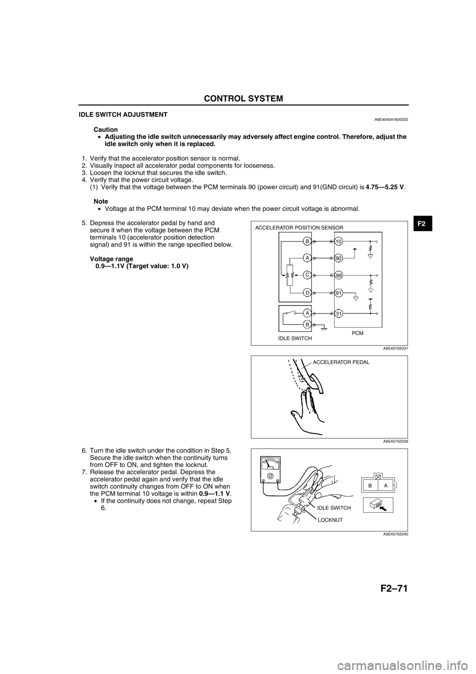
5. Depress the accelerator pedal by hand and
secure it when the voltage between the PCM
terminals 10 (accelerator position detection
signal) and 91 is within the range specified below.
Voltage range
0.9—1.1V (Target value: 1.0 V)
6. Turn the idle switch under the condition in Step 5.
Secure the idle switch when the continuity turns
from OFF to ON, and tighten the locknut.
7. Release the accelerator pedal. Depress the
accelerator pedal again and verify that the idle
switch continuity changes from OFF to ON when
the PCM terminal 10 voltage is within 0.9—1.1 V.
•If the continuity does not change, repeat Step
6.
End Of Sie
ACCELERATOR POSITION SENSOR
IDLE SWITCHPCM B
A
C
D
A
B31 10
90
88
91
A6E40702037
ACCELERATOR PEDAL
A6E40702039
IDLE SWITCH
LOCKNUTA
B
A6E40702040
Page 224 of 909

F2–72
CONTROL SYSTEM
ACCELERATOR POSITION SENSOR INSPECTIONA6E404041602201
Note
•Perform the following test only when directed.
1. Visually inspect all accelerator pedal components for looseness.
2. Verify that the accelerator position sensor is installed to the accelerator pedal properly.
3. Verify the power circuit voltage.
(1) Verify that the voltage between the PCM terminal 90 (power circuit) and 91 (GND circuit) is 4.75—5.25 V.
Note
•Voltage at the PCM terminal 10 may deviate when the power circuit voltage is abnormal.
4. Verify that the voltage between the PCM
terminals 10 (accelerator position detection
signal) and 91 is as shown below according to the
accelerator pedal conditions.
•If the circuit is okay, replace the accelerator
position sensor.
Specification
Circuit Open/Short Inspection
1. Inspect for open/short circuit in the following
wiring harnesses.
•If there is open/short circuit, repair or replace
wiring harnesses.
Open circuit
•Power circuit
—Accelerator position sensor terminal A and
PCM terminal 90
•Signal circuit
—Accelerator position sensor terminal B and
PCM terminal 10
—Accelerator position sensor terminal C and
PCM terminal 88
•GND circuit
—Accelerator position sensor terminal D and PCM terminal 91
Short circuit
•Power circuit
—Accelerator position sensor terminal A and PCM terminal 90 to GND
•Signal circuit
—Accelerator position sensor terminal B and PCM terminal 10 to power circuit
—Accelerator position sensor terminal B and PCM terminal 10 to GND
—Accelerator position sensor terminal C and PCM terminal 88 to power circuit
—Accelerator position sensor terminal C and PCM terminal 88 to GND
End Of Sie
Accelerator pedal
conditionOutput voltage (V)
Fully released 0.45—0.75 (Target value: 0.6)
Gradually depressed Increases linearly
Fully depressed 3.35—4.03 (Target value: 3.6)
ACCELERATOR POSITION SENSOR
PCM
B
A
C
D10
90
88
91
A6E40702041
ACCELERATOR POSITION SENSOR
HARNESS SIDE CONNECTOR
A B
C D
A6E40702042
Page 225 of 909

CONTROL SYSTEM
F2–73
F2
ACCELERATOR POSITION SENSOR ADJUSTMENTA6E404041602202
Caution
•Adjusting the accelerator position sensor unnecessarily may adversely affect engine control.
Therefore, adjust accelerator position sensor only when it is replaced.
Note
•Accelerator position sensor adjustment is based on the output voltage with the accelerator pedal fully
released. Therefore, be sure to adjust according to the following procedure. (Begin adjustment with the
accelerator pedal fully released.)
1. Visually inspect all accelerator pedal components for looseness.
2. Install the accelerator position sensor.
3. Verify the power circuit voltage.
(1) Verify that the voltage between the PCM terminals 90 (power circuit) and 91 (GND circuit) is 4.75—5.25 V.
Note
•Voltage at the PCM terminal 10 may deviate when the power circuit voltage is abnormal.
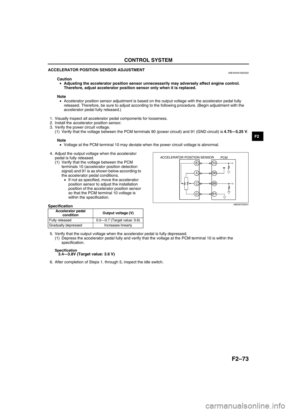
4. Adjust the output voltage when the accelerator
pedal is fully released.
(1) Verify that the voltage between the PCM
terminals 10 (accelerator position detection
signal) and 91 is as shown below according to
the accelerator pedal conditions.
•If not as specified, move the accelerator
position sensor to adjust the installation
position of the accelerator position sensor
so that the PCM terminal 10 voltage is
within the specification.
Specification
5. Verify that the output voltage when the accelerator pedal is fully depressed.
(1) Depress the accelerator pedal fully and verify that the voltage at the PCM terminal 10 is within the
specification.
Specification3.4—3.8V (Target value: 3.6 V)
6. After completion of Steps 1. through 5, inspect the idle switch.
End Of SieAccelerator pedal
conditionOutput voltage (V)
Fully released 0.5—0.7 (Target value: 0.6)
Gradually depressed Increases linearly
ACCELERATOR POSITION SENSOR
PCM
B
A
C
D10
90
88
91
A6E40702041
Page 226 of 909

F2–74
CONTROL SYSTEM
MASS AIR FLOW (MAF)/INTAKE AIR TEMPERATURE (IAT) SENSOR INSPECTIONA6E404013210201
Note
•Perform the following test only when directed.
•Perform “MAF Correction” after replacing the MAF/IAT sensor. (See F2–35 MAF Correction.)
MAF Sensor Voltage Inspection
1. Turn the engine switch to ON.
2. Monitor the MAF PID using the WDS or equivalent.
•If not as specified, perform the “Circuit Open/Short Inspection”.
MAF PID
0.0—1.0 V
3. Start the engine and warm up the engine completely.
4. Monitor the MAF PID using the WDS or equivalent at idle.
•If not as specified, perform the “Circuit Open/Short Inspection”.
MAF PID
1.5—2.1 V
MAF Sensor CIrcuit Open/Short Inspection
1. Inspect for open/short circuit in the following
wiring harnesses.
•If there is open/short circuit, repair or replace
wiring harnesses.
Open circuit
•Power circuit
—MAF/IAT sensor terminal A and PCM control
relay terminal C
•Signal circuit
—MAF/IAT sensor terminal C and PCM terminal
9
•GND circuit
—MAF/IAT sensor terminal B and PCM terminal 14
Short circuit
•Power circuit
—MAF/IAT sensor terminal A and PCM control relay terminal C to GND
•Signal circuit
—MAF/IAT sensor terminal C and PCM terminal 9 to power circuit
—MAF/IAT sensor terminal C and PCM terminal 9 to GND
MAF/IAT SENSOR
HARNESS SIDE CONNECTOR
A
B
C
D E
A6E40702043
Page 227 of 909

CONTROL SYSTEM
F2–75
F2
IAT Sensor No.1 Resistance Inspection
1. Disconnect the MAF/IAT sensor connector.
2. Measure the resistance between MAF/IAT sensor terminals D and E using an ohmmeter.
•If not as specified, replace the MAF/IAT sensor.
Specification
IAT Sensor No.1 CIrcuit Open/Short Inspection
1. Inspect for open/short circuit in the following wiring harnesses.
•If there is open/short circuit, repair or replace wiring harnesses.
Open circuit
•Signal circuit
—MAF/IAT sensor terminal D and PCM terminal 60
•GND circuit
—MAF/IAT sensor terminal E and PCM terminal 91
Short circuit
•Signal circuit
—MAF/IAT sensor terminal D and PCM terminal 60 to power circuit
—MAF/IAT sensor terminal D and PCM terminal 60 to GND
End Of Sie
INTAKE AIR TEMPERATURE (IAT) SENSOR NO.2 INSPECTIONA6E404018845201
Note
•Perform the following test only when directed.
Resistance Inspection
1. Place the IAT sensor No.2 in water with a thermometer, and heat the water gradually.
2. Measure the resistance between the IAT sensor
No.2 terminals using an ohmmeter.
•If not as specified, replace the IAT sensor
No.2.
Specification
Circuit Open/Short Inspection
1. Inspect for open/short circuit in the following wiring harnesses.
•If there is open/short circuit, repair or replace wiring harnesses.
Open circuit
•Signal circuit
—IAT sensor No.2 terminal A and PCM terminal 8
•GND circuit
—IAT sensor No.2 terminal B and PCM terminal 91
Short circuit
•Signal circuit
—IAT sensor No.2 terminal A and PCM terminal 8 to power circuit
—IAT sensor No.2 terminal A and PCM terminal 8 to GND
End Of Sie
Ambient temperature (°C
{°F})Resistance (kilohm)
20 {68} 2.21—2.69
Water temperature (°C {°F}) Resistance (kilohm)
20 {68} 2.21—2.69
80 {176} 0.29—0.35
A B
A6E40702044
Page 228 of 909

F2–76
CONTROL SYSTEM
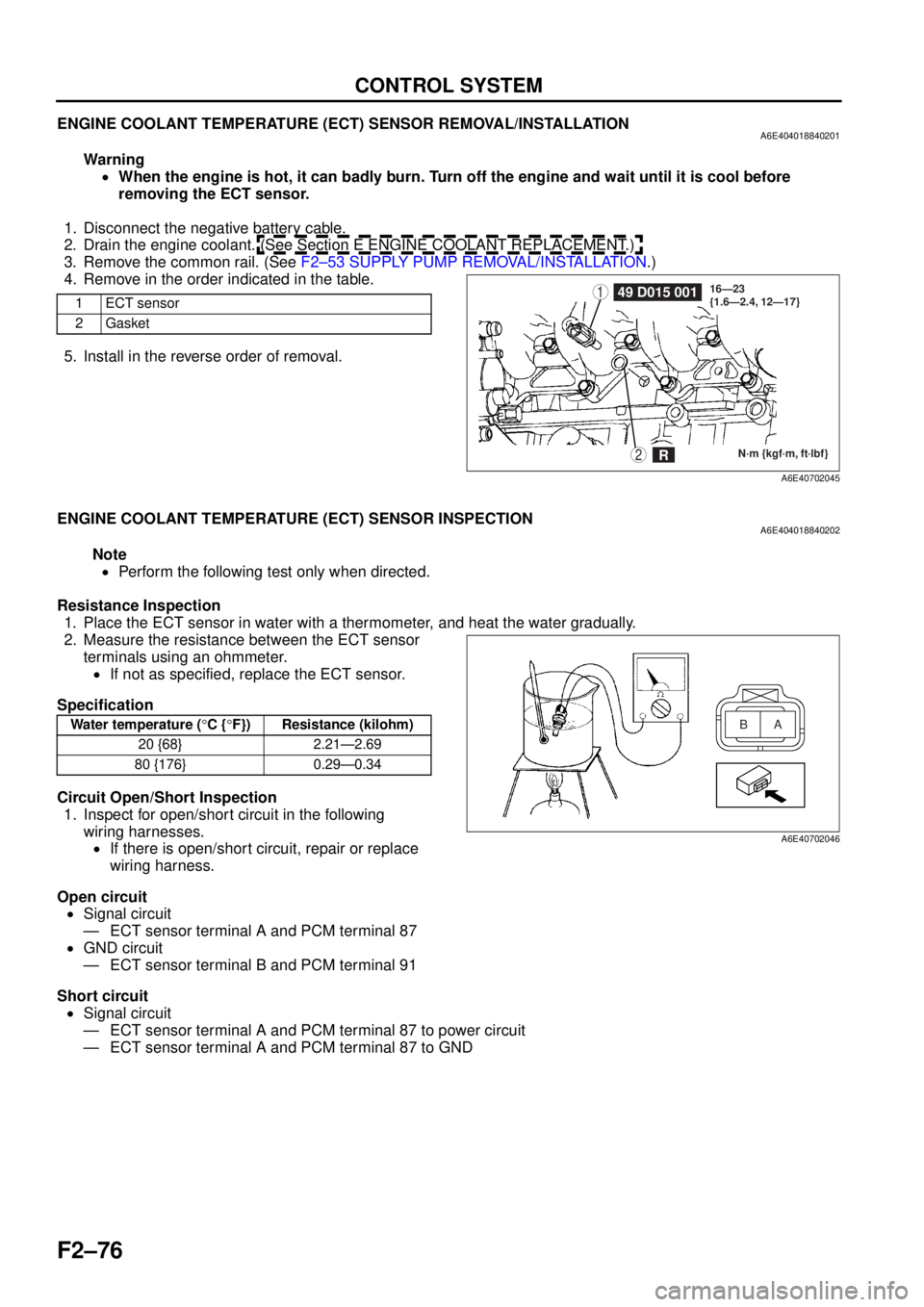
ENGINE COOLANT TEMPERATURE (ECT) SENSOR REMOVAL/INSTALLATIONA6E404018840201
Warning•When the engine is hot, it can badly burn. Turn off the engine and wait until it is cool before
removing the ECT sensor.
1. Disconnect the negative battery cable.
2. Drain the engine coolant. (See Section E ENGINE COOLANT REPLACEMENT.)
3. Remove the common rail. (See F2–53 SUPPLY PUMP REMOVAL/INSTALLATION .)
4. Remove in the order indicated in the table.
5. Install in the reverse order of removal.
End Of Sie
ENGINE COOLANT TEMPERATURE (ECT) SENSOR INSPECTIONA6E404018840202
Note
• Perform the following test only when directed.
Resistance Inspection 1. Place the ECT sensor in water with a thermometer, and heat the water gradually.
2. Measure the resistance between the ECT sensor terminals using an ohmmeter.
• If not as specified, replace the ECT sensor.
Specification
Circuit Open/Short Inspection 1. Inspect for open/short circuit in the following
wiring harnesses.• If there is open/short circuit, repair or replace
wiring harness.
Open circuit • Signal circuit
— ECT sensor terminal A and PCM terminal 87
• GND circuit
— ECT sensor terminal B and PCM terminal 91
Short circuit • Signal circuit
— ECT sensor terminal A and PCM terminal 87 to power circuit
— ECT sensor terminal A and PCM terminal 87 to GND
End Of Sie
1ECT sensor
2Gasket149 D015 001
N·m {kgf·m, ft·lbf}
16—23
{1.6—2.4, 12—17}2R
A6E40702045
Water temperature (
°C { °F}) Resistance (kilohm)
20 {68} 2.21—2.69
80 {176} 0.29—0.34A
B
A6E40702046
Page 229 of 909

CONTROL SYSTEM
F2–77
F2
FUEL TEMPERATURE SENSOR INSPECTIONA6E404013350201
Note
•Perform the following test only when directed.
Resistance Inspection
1. Disconnect the negative battery cable.
2. Remove the supply pump. (See F2–53 SUPPLY PUMP REMOVAL/INSTALLATION.)
3. Measure the resistance between the fuel
temperature sensor terminals using an
ohmmeter.
•If not as specified, repair the supply pump.
(See F2–54 SUPPLY PUMP INSPECTION.)
Specification
Circuit Open/Short Inspection
1. Inspect for open/short circuit in the following
wiring harnesses.
•If there is open/short circuit, repair or replace wiring harness.
Open circuit
•Signal circuit
—Fuel temperature sensor terminal A and PCM terminal 35
•GND circuit
—Fuel temperature sensor terminal B and PCM terminal 91
Short circuit
•Signal circuit
—Fuel temperature sensor terminal A and PCM terminal 35 to power circuit
—Fuel temperature sensor terminal A and PCM terminal 35 to GND
End Of Sie
Ambient temperature (°C
{°F})Resistance (kilohm)
20 {68} 2.0—3.0
A
B
A6E40702047
Page 230 of 909

F2–78
CONTROL SYSTEM
BOOST SENSOR INSPECTIONA6E404013214201
Note
•Perform the following test only when directed.
Visual Inspection
1. Inspect the boost sensor for damage and cracks.
•If not as specified, replace the boost sensor.
2. Inspect vacuum hose for improper routing, kinks or leakage.
•If there is any malfunction, repair or replace suspected hose.
Voltage Inspection
1. Turn the engine switch to ON.
2. Monitor the MAP PID using the WDS or equivalent.
•If not as specified, perform the “Circuit Open/Short Inspection”.
MAP PID
2.1—2.5 V
3. Start the engine and warm up the engine completely.
4. Monitor the MAP PID using the WDS or equivalent at idle.
•If not as specified, perform the “Circuit Open/Short Inspection”.
MAP PID
2.1—2.5 V
Circuit Open/Short Inspection
1. Inspect for open/short circuit in the following
wiring harnesses.
•If there is open/short circuit, repair or replace
wiring harnesses.
Open circuit
•Power circuit
—Boost sensor terminal C and PCM terminal 90
•Signal circuit
—Boost sensor terminal B and PCM terminal 36
•GND circuit
—Boost sensor terminal A and PCM terminal 91
Short circuit
•Power circuit
—Boost sensor terminal C and PCM terminal 90 to GND
•Signal circuit
—Boost sensor terminal B and PCM terminal 36 to power circuit
—Boost sensor terminal B and PCM terminal 36 to GND
End Of Sie
BOOST SENSOR
HARNESS SIDE CONNECTOR
A
B C
A6E40702048