MAZDA 6 2002 Workshop Manual Suplement
Manufacturer: MAZDA, Model Year: 2002, Model line: 6, Model: MAZDA 6 2002Pages: 909, PDF Size: 17.16 MB
Page 191 of 909
INTAKE-AIR SYSTEM
F2–39
F2
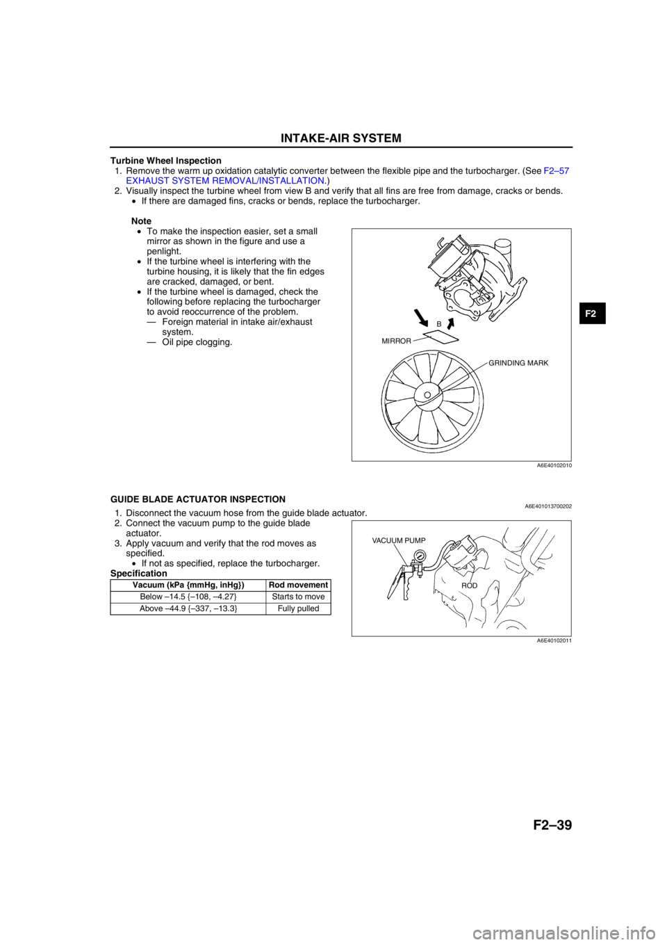
Turbine Wheel Inspection
1. Remove the warm up oxidation catalytic converter between the flexible pipe and the turbocharger. (See F2–57
EXHAUST SYSTEM REMOVAL/INSTALLATION.)
2. Visually inspect the turbine wheel from view B and verify that all fins are free from damage, cracks or bends.
•If there are damaged fins, cracks or bends, replace the turbocharger.
Note
•To make the inspection easier, set a small
mirror as shown in the figure and use a
penlight.
•If the turbine wheel is interfering with the
turbine housing, it is likely that the fin edges
are cracked, damaged, or bent.
•If the turbine wheel is damaged, check the
following before replacing the turbocharger
to avoid reoccurrence of the problem.
—Foreign material in intake air/exhaust
system.
—Oil pipe clogging.
End Of Sie
GUIDE BLADE ACTUATOR INSPECTIONA6E4010137002021. Disconnect the vacuum hose from the guide blade actuator.
2. Connect the vacuum pump to the guide blade
actuator.
3. Apply vacuum and verify that the rod moves as
specified.
•If not as specified, replace the turbocharger.
Specification
End Of Sie
MIRRORB
GRINDING MARK
A6E40102010
Vacuum (kPa {mmHg, inHg}) Rod movement
Below –14.5 {–108, –4.27} Starts to move
Above –44.9 {–337, –13.3} Fully pulled
VACUUM PUMP
ROD
A6E40102011
Page 192 of 909
F2–40
INTAKE-AIR SYSTEM
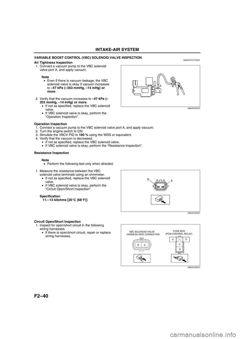
VARIABLE BOOST CONTROL (VBC) SOLENOID VALVE INSPECTIONA6E401013710201Air Tightness Inspection
1. Connect a vacuum pump to the VBC solenoid
valve port A, and apply vacuum.
Note
•Even if there is vacuum leakage, the VBC
solenoid valve is okay if vacuum increases
to –47 kPa {–353 mmHg, –14 inHg} or
more.
2. Verify that the vacuum increases to –47 kPa {–
353 mmHg, –14 inHg} or more.
•If not as specified, replace the VBC solenoid
valve.
•If VBC solenoid valve is okay, perform the
“Operation Inspection”.
Operation Inspection
1. Connect a vacuum pump to the VBC solenoid valve port A, and apply vacuum.
2. Turn the engine switch to ON.
3. Simulate the VBCV PID to 100 % using the WDS or equivalent.
4. Verify that the vacuum is decreased.
•If not as specified, replace the VBC solenoid valve.
•If VBC solenoid valve is okay, perform the “Resistance Inspection”.
Resistance Inspection
Note
•Perform the following test only when directed.
1. Measure the resistance between the VBC
solenoid valve terminals using an ohmmeter.
•If not as specified, replace the VBC solenoid
valve.
•If VBC solenoid valve is okay, perform the
“Circuit Open/Short Inspection”.
Specification
11—13 kilohms [20°C {68°F}]
Circuit Open/Short Inspection
1. Inspect for open/short circuit in the following
wiring harnesses.
•If there is open/short circuit, repair or replace
wiring harnesses.
A
A6E40102012
A B
A6E40102031
AA
BC
DE VBC SOLENOID VALVE
HARNESS SIDE CONNECTORFUSE BOX
(PCM CONTROL RELAY)
A6E40102014
Page 193 of 909
INTAKE-AIR SYSTEM
F2–41
F2
Open circuit
•If there is no continuity, the circuit is open. Repair or replace the harness.
—VBC solenoid valve terminal A (harness-side) and PCM control relay terminal C
—VBC solenoid valve terminal B (harness-side) and PCM connector terminal 67
Short circuit
•If there is continuity, the circuit is shorted. Repair or replace the harness.
—VBC solenoid valve terminal A (harness-side) and GND
—VBC solenoid valve terminal B (harness-side) and power supply
End Of Sie
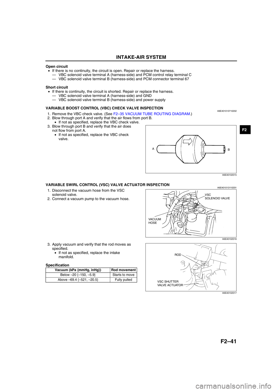
VARIABLE BOOST CONTROL (VBC) CHECK VALVE INSPECTIONA6E4010137102021. Remove the VBC check valve. (See F2–35 VACUUM TUBE ROUTING DIAGRAM.)
2. Blow through port A and verify that the air flows from port B.
•If not as specified, replace the VBC check valve.
3. Blow through port B and verify that the air does
not flow from port A.
•If not as specified, replace the VBC check
valve.
End Of Sie
VARIABLE SWIRL CONTROL (VSC) VALVE ACTUATOR INSPECTIONA6E4010131102011. Disconnect the vacuum hose from the VSC
solenoid valve.
2. Connect a vacuum pump to the vacuum hose.
3. Apply vacuum and verify that the rod moves as
specified.
•If not as specified, replace the intake
manifold.
Specification
End Of Sie
A
B
A6E40102015
Vacuum (kPa {mmHg, inHg}) Rod movement
Below –20 {–150, –5.9} Starts to move
Above –69.4 {–521, –20.5} Fully pulled
VSC
SOLENOID VALVE
VACUUM
HOSE
A6E40102016
ROD
VSC SHUTTER
VALVE ACTUATOR
A6E40102017
Page 194 of 909
F2–42
INTAKE-AIR SYSTEM
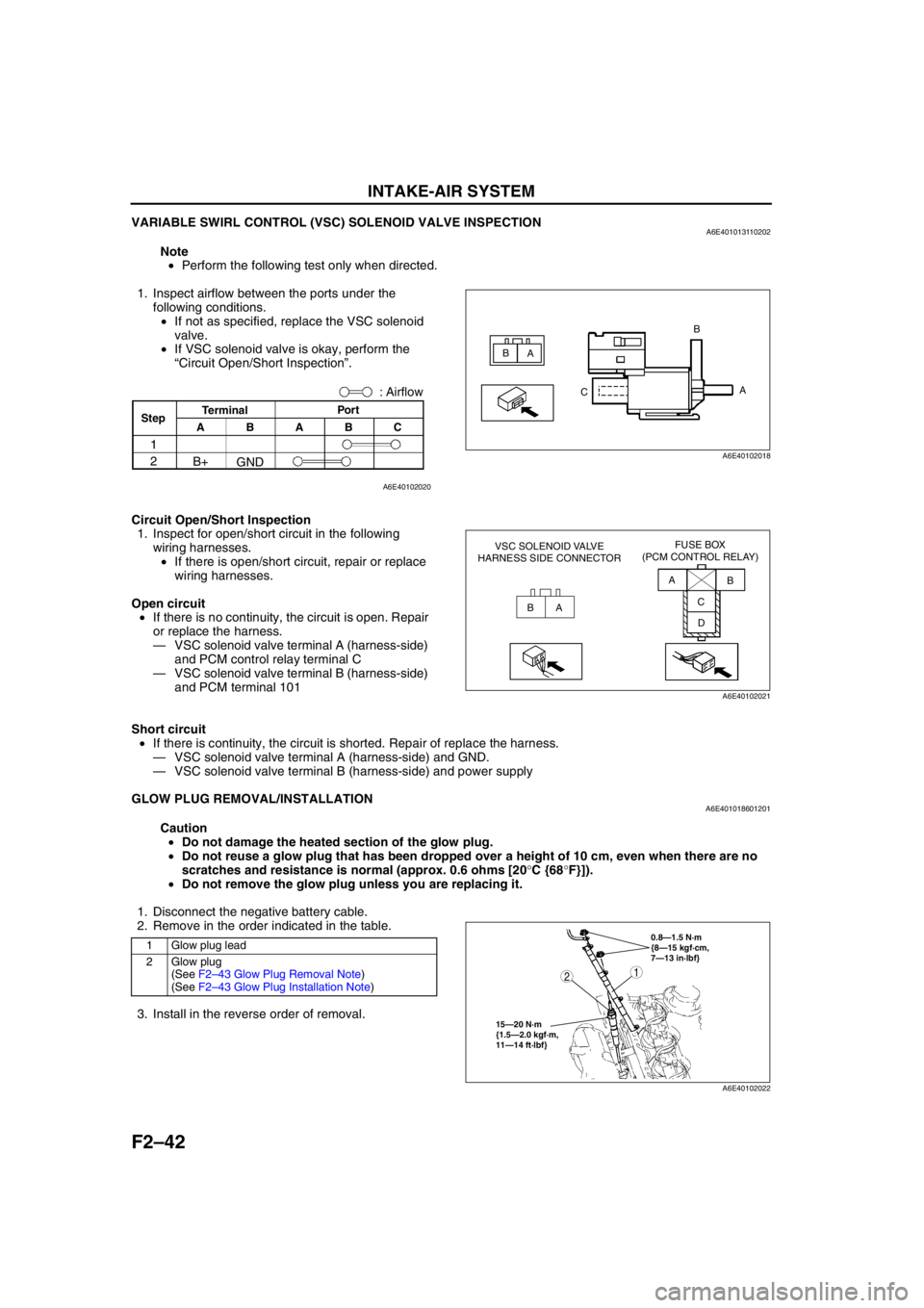
VARIABLE SWIRL CONTROL (VSC) SOLENOID VALVE INSPECTIONA6E401013110202
Note
•Perform the following test only when directed.
1. Inspect airflow between the ports under the
following conditions.
•If not as specified, replace the VSC solenoid
valve.
•If VSC solenoid valve is okay, perform the
“Circuit Open/Short Inspection”.
Circuit Open/Short Inspection
1. Inspect for open/short circuit in the following
wiring harnesses.
•If there is open/short circuit, repair or replace
wiring harnesses.
Open circuit
•If there is no continuity, the circuit is open. Repair
or replace the harness.
—VSC solenoid valve terminal A (harness-side)
and PCM control relay terminal C
—VSC solenoid valve terminal B (harness-side)
and PCM terminal 101
Short circuit
•If there is continuity, the circuit is shorted. Repair of replace the harness.
—VSC solenoid valve terminal A (harness-side) and GND.
—VSC solenoid valve terminal B (harness-side) and power supply
End Of Sie
GLOW PLUG REMOVAL/INSTALLATIONA6E401018601201
Caution
•Do not damage the heated section of the glow plug.
•Do not reuse a glow plug that has been dropped over a height of 10 cm, even when there are no
scratches and resistance is normal (approx. 0.6 ohms [20°C {68°F}]).
•Do not remove the glow plug unless you are replacing it.
1. Disconnect the negative battery cable.
2. Remove in the order indicated in the table.
3. Install in the reverse order of removal.
A
A B
B
C
A6E40102018
: Airflow
Por t
C B
A
GND B+
ABTerminal
Step
1
2
A6E40102020
BAA
B
C
D VSC SOLENOID VALVE
HARNESS SIDE CONNECTORFUSE BOX
(PCM CONTROL RELAY)
A6E40102021
1 Glow plug lead
2Glow plug
(See F2–43 Glow Plug Removal Note)
(See F2–43 Glow Plug Installation Note)0.8—1.5 N·m
{8—15 kgf·cm,
7—13 in·lbf}
15—20 N·m
{1.5—2.0 kgf·m,
11—14 ft·lbf}
12
A6E40102022
Page 195 of 909
INTAKE-AIR SYSTEM
F2–43
F2
Glow Plug Removal Note
1. When removing the glow plug, first loosen it at least one pitch using a tool, then loosen by hand.
Glow Plug Installation Note
1. Tighten the glow plug at least one pitch by hand, and continue tightening with a tool.
End Of Sie
GLOW PLUG INSPECTIONA6E401018601202
Note
•Perform the following test only when directed.
1. Remove the glow plug lead. (See F2–42 GLOW PLUG REMOVAL/INSTALLATION.)
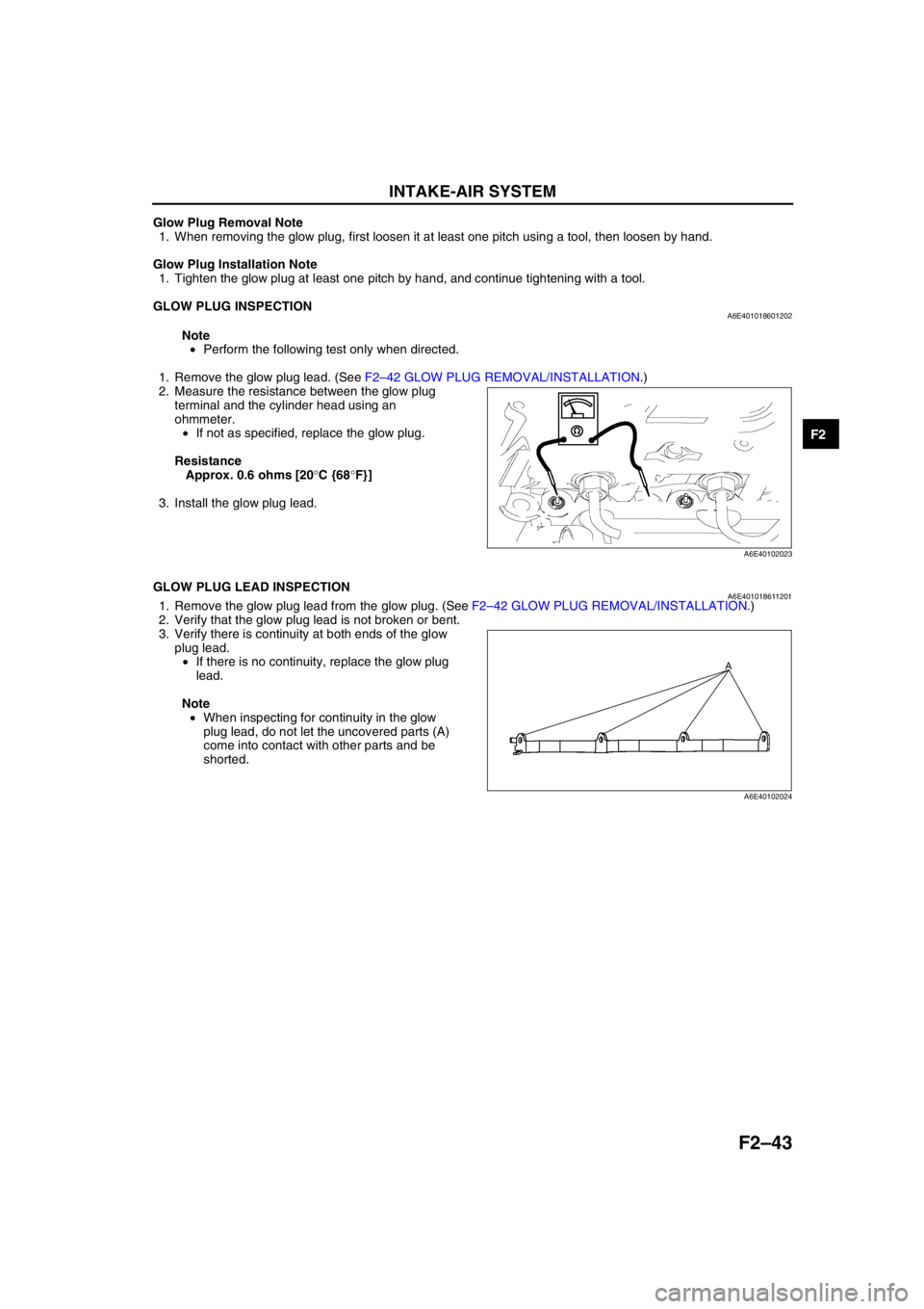
2. Measure the resistance between the glow plug
terminal and the cylinder head using an
ohmmeter.
•If not as specified, replace the glow plug.
Resistance
Approx. 0.6 ohms [20°C {68°F}]
3. Install the glow plug lead.
End Of Sie
GLOW PLUG LEAD INSPECTIONA6E4010186112011. Remove the glow plug lead from the glow plug. (See F2–42 GLOW PLUG REMOVAL/INSTALLATION.)
2. Verify that the glow plug lead is not broken or bent.
3. Verify there is continuity at both ends of the glow
plug lead.
•If there is no continuity, replace the glow plug
lead.
Note
•When inspecting for continuity in the glow
plug lead, do not let the uncovered parts (A)
come into contact with other parts and be
shorted.
A6E40102023
A
A6E40102024
Page 196 of 909
F2–44
INTAKE-AIR SYSTEM
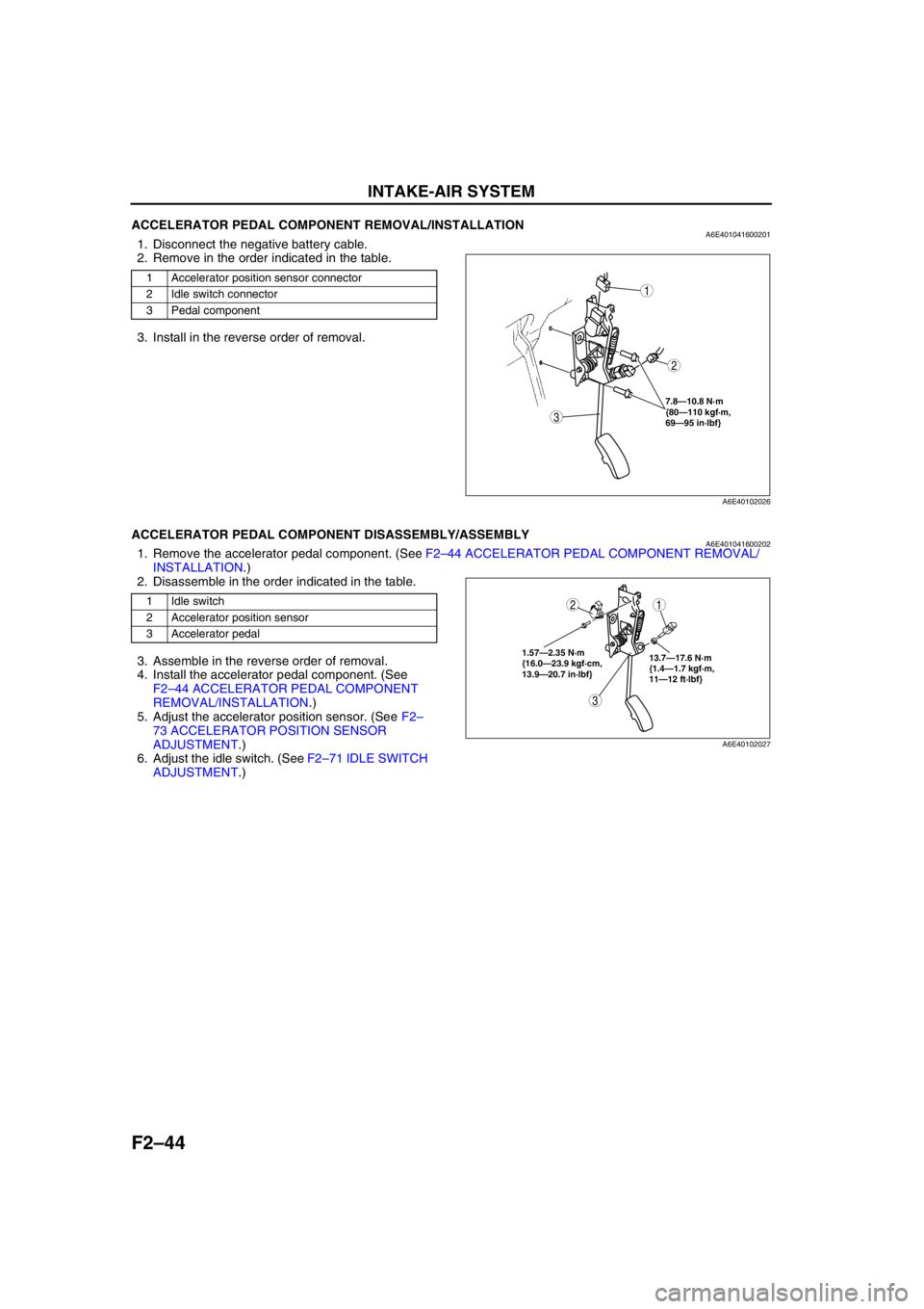
End Of SieACCELERATOR PEDAL COMPONENT REMOVAL/INSTALLATIONA6E4010416002011. Disconnect the negative battery cable.
2. Remove in the order indicated in the table.
3. Install in the reverse order of removal.
End Of Sie
ACCELERATOR PEDAL COMPONENT DISASSEMBLY/ASSEMBLYA6E4010416002021. Remove the accelerator pedal component. (See F2–44 ACCELERATOR PEDAL COMPONENT REMOVAL/
INSTALLATION.)
2. Disassemble in the order indicated in the table.
3. Assemble in the reverse order of removal.
4. Install the accelerator pedal component. (See
F2–44 ACCELERATOR PEDAL COMPONENT
REMOVAL/INSTALLATION.)
5. Adjust the accelerator position sensor. (See F2–
73 ACCELERATOR POSITION SENSOR
ADJUSTMENT.)
6. Adjust the idle switch. (See F2–71 IDLE SWITCH
ADJUSTMENT.)
End Of Sie
1 Accelerator position sensor connector
2 Idle switch connector
3 Pedal component
7.8—10.8 N·m
{80—110 kgf·m,
69—95 in·lbf}
3
1
2
A6E40102026
1 Idle switch
2 Accelerator position sensor
3 Accelerator pedal
3
12
1.57—2.35 N·m
{16.0—23.9 kgf·cm,
13.9—20.7 in·lbf}13.7—17.6 N·m
{1.4—1.7 kgf·m,
11—12 ft·lbf}
A6E40102027
Page 197 of 909
FUEL SYSTEM
F2–45
F2
BEFORE REPAIR PROCEDUREA6E401201006203
Warning
•Fuel vapor is hazardous. It can easily ignite, causing serious injury and damage. Always keep
sparks and flames away from fuel.
•Fuel line spills and leads are dangerous. Fuel can ignite and cause serious injuries or death and
damage. Fuel can also irritate skin and eyes. To prevent this, always complete the following “Fuel
Line Safety Procedures”.
Fuel Line Safety Procedures
Note
•Fuel in the fuel system is under high pressure when the engine is not running.
1. Avoid fuel line spills and leaks by completing the following procedures.
(1) Remove the fuel-filler cap and release the pressure in the fuel tank.
(2) When disconnecting a fuel line hose, wrap a rag around it to protect against fuel leakage.
(3) Plug the hose after removal.
End Of Sie
AFTER REPAIR PROCEDUREA6E401201006204
Warning
•Fuel line spills and leakage are dangerous. Fuel can ignite and cause serious injuries or death and
damage. When installing the fuel hose, observe “Fuel Hose Installation” described below.
Fuel Line Air Bleeding
Caution
•Continuously cranking the engine for over 30 s can damage the battery and the starter.
1. Continue cranking the engine for 30 s and stop for 5—10 s until the engine starts.
Fuel Hose Installation
1. Verify that there is no damage or deformation on the fuel hose and fuel pipe when installing.
End Of Sie
FUEL TANK REMOVAL/INSTALLATIONA6E401242110201
Warning
•Repairing a fuel tank that has not been properly steam cleaned can be dangerous. Explosion or
fire may cause death or serious injury. Always properly steam clean a fuel tank before repairing it.
•Fuel line spills and leakage are dangerous. Fuel can also irritate skin and eyes. To prevent this, do
not damage the sealing surface of the fuel gauge sender unit when removing or installing.
Caution
•Disconnecting/connecting the quick release connector without cleaning it may possibly cause
damage to the fuel pipe and quick release connector. Always clean the quick release connector
joint area before disconnecting/connecting using a cloth or soft brush, and make sure that it is
free of foreign material.
FUEL SYSTEM
Page 198 of 909
F2–46
FUEL SYSTEM
1. Verify that vehicle is level.
2. Complete the “BEFORE REPAIR PROCEDURE”. (See F2–45 BEFORE REPAIR PROCEDURE.)
3. Disconnect the negative battery cable.
4. Remove the rear seat cushion.
5. Remove the service hole cover.
6. Remove the plastic fuel hose from the fuel gauge sender unit. (See F2–47 Plastic Fuel Hose Removal Note.)
(See F2–48 Plastic Fuel Hose Installation Note.)
7. Remove the fuel gauge sender unit connector.
8. Remove the fuel tank gauge cap. (See F2–47 Fuel Tank Gauge Cap Removal Note.)
9. Remove the fuel gauge sender unit. (See F2–48 Fuel Gauge Sender Unit Installation Note.)
10. Siphon the fuel from the fuel tank.
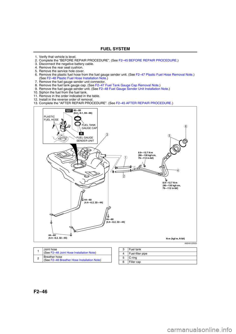
11. Remove in the order indicated in the table.
12. Install in the reverse order of removal.
13. Complete the “AFTER REPAIR PROCEDURE”. (See F2–45 AFTER REPAIR PROCEDURE.)
.
44—60
{4.4—6.2, 32—44}44—60
{4.4—6.2, 32—44} 44—60
{4.4—6.2, 32—44}
N·m {kgf·m, ft·lbf}
8.9—12.7 N·m
{90—130 kgf·cm,
79—112 in·lbf}
8.9—12.7 N·m
{90—130 kgf·cm,
79—112 in·lbf}
5
4
3
2
1
6
80—90
{8.2—9.1, 59—66}
R
PLASTIC
FUEL HOSE
FUEL GAUGE
SENDER UNITFUEL TANK
GAUGE CAP
SST
A6E40122025
1Joint hose
(See F2–48 Joint Hose Installation Note)
2Breather hose
(See F2–48 Breather Hose Installation Note)3 Fuel tank
4 Fuel-filler pipe
5 C-ring
6 Filler cap
Page 199 of 909
FUEL SYSTEM
F2–47
F2
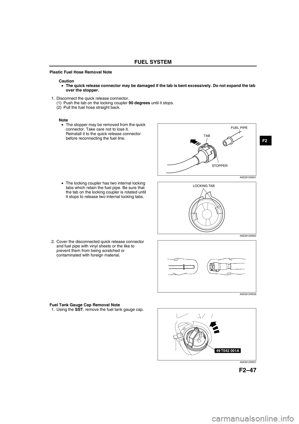
Plastic Fuel Hose Removal Note
Caution
•The quick release connector may be damaged if the tab is bent excessively. Do not expand the tab
over the stopper.
1. Disconnect the quick release connector.
(1) Push the tab on the locking coupler 90 degrees until it stops.
(2) Pull the fuel hose straight back.
Note
•The stopper may be removed from the quick
connector. Take care not to lose it.
Reinstall it to the quick release connector
before reconnecting the fuel line.
•The locking coupler has two internal locking
tabs which retain the fuel pipe. Be sure that
the tab on the locking coupler is rotated until
it stops to release two internal locking tabs.
2. Cover the disconnected quick release connector
and fuel pipe with vinyl sheets or the like to
prevent them from being scratched or
contaminated with foreign material.
Fuel Tank Gauge Cap Removal Note
1. Using the SST, remove the fuel tank gauge cap.
FUEL PIPE
STOPPER TAB
A6E3912W001
LOCKING TAB
A6E3912W002
A6E3912W039
49 T042 001A
A6A3912W007
Page 200 of 909
F2–48
FUEL SYSTEM
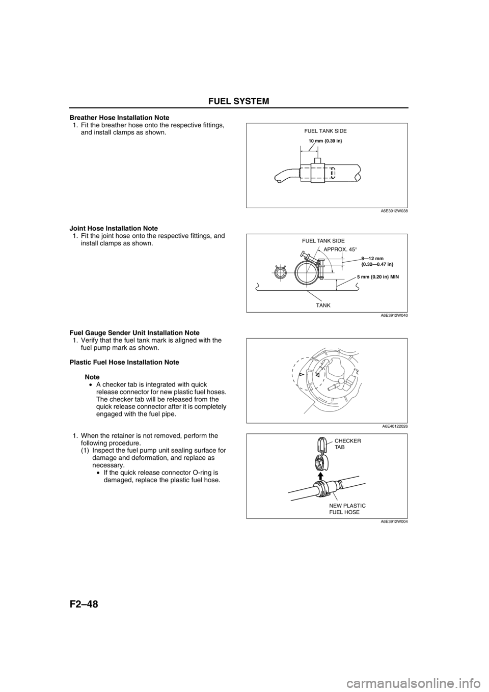
Breather Hose Installation Note
1. Fit the breather hose onto the respective fittings,
and install clamps as shown.
Joint Hose Installation Note
1. Fit the joint hose onto the respective fittings, and
install clamps as shown.
Fuel Gauge Sender Unit Installation Note
1. Verify that the fuel tank mark is aligned with the
fuel pump mark as shown.
Plastic Fuel Hose Installation Note
Note
•A checker tab is integrated with quick
release connector for new plastic fuel hoses.
The checker tab will be released from the
quick release connector after it is completely
engaged with the fuel pipe.
1. When the retainer is not removed, perform the
following procedure.
(1) Inspect the fuel pump unit sealing surface for
damage and deformation, and replace as
necessary.
•If the quick release connector O-ring is
damaged, replace the plastic fuel hose.
FUEL TANK SIDE
10 mm {0.39 in}
A6E3912W038
8—12 mm
{0.32—0.47 in}
5 mm {0.20 in} MIN
TANK
APPROX. 45° FUEL TANK SIDE
A6E3912W040
A6E40122026
CHECKER
TA B
NEW PLASTIC
FUEL HOSE
A6E3912W004