MAZDA 6 2002 Workshop Manual Suplement
Manufacturer: MAZDA, Model Year: 2002, Model line: 6, Model: MAZDA 6 2002Pages: 909, PDF Size: 17.16 MB
Page 211 of 909
EMISSION SYSTEM
F2
F2–59
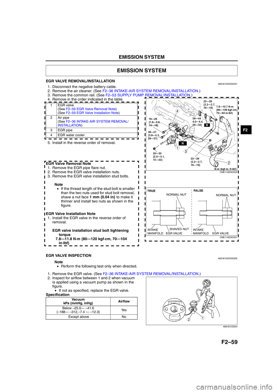
EGR VALVE REMOVAL/INSTALLATIONA6E4016203002011. Disconnect the negative battery cable.
2. R em ove t he a ir c le a ne r. (S ee F 2–36 IN TA K E-A IR SYS TEM RE MOVA L/I NSTA LL AT IO N.)
3 . R em ove t he co m mon r ai l. (S ee F 2–53 SUPPLY PU MP R EM OVA L/IN STA LLAT IO N.)
4. Remove in the order indicated in the table.
.
5. Install in the reverse order of removal.
EGR Valve Removal Note 1. Remove the EGR pipe flare nut.
2. Remove the EGR valve installation nuts.
3. Remove the EGR valve installation stud bolts.
Note• If the thread length of the stud bolt is smaller
than the two nuts used for stud bolt removal,
shave a nut face 1 mm {0.04 in} to make it
thinner and install two nuts as shown in the
figure.
EGR Valve Installation Note 1. Install the EGR valve in the reverse order of removal.
EGR valve installation stud bolt tightening torque
7.8—11.8 N·m {80—120 kgf·cm, 70—104 in·lbf}
End Of Sie
EGR VALVE INSPECTIONA6E401620300202
Note
• Perform the following test only when directed.
1 . R em ove t h e EG R va lv e . ( See F 2–36 IN TA K E-A IR SYS TEM RE MOVA L/I NSTA LL AT IO N.)
2. Inspect for airflow between 1 and 2 when vacuum is applied using a vacuum pump as shown in the
figure.• If not as specified, replace the EGR valve.
Specification
End Of Sie
EMISSION SYSTEM
1EGR valve (See F 2–5 9 EG R V alv e R em oval N ote )
(See F2 –5 9 E G R V alv e In sta llat ion Not e)
2Air pipe (See F2 –3 6 IN TAKE-AIR SYSTEM RE MOVAL/
INS TA LL ATION )
3 EGR pipe
4 EGR water cooler
CME116EW2002
SHAVED NUT FALSE
TRUE
EGR VALVE
INTAKE
MANIFOLDEGR VALVE
INTAKE
MANIFOLD
NORMAL NUTNORMAL NUT
CME116EW2001
Vacuum
kPa {mmHg, inHg} Airflow
Below –25.0 — – 41.6
{ – 188 — – 312, –7.4 — – 12.3} Ye s
Except above No
12
A6E40122024
Page 212 of 909
F2–60
EMISSION SYSTEM
EGR SOLENOID VALVE (VACUUM) INSPECTIONA6E401618741201
Note
•Perform the following inspection only when directed.
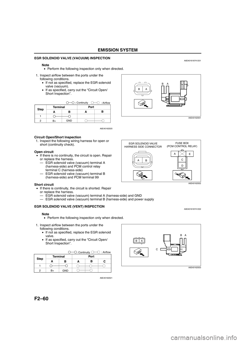
1. Inspect airflow between the ports under the
following conditions.
•If not as specified, replace the EGR solenoid
valve (vacuum).
•If as specified, carry out the “Circuit Open/
Short Inspection”.
Circuit Open/Short Inspection
1. Inspect the following wiring harness for open or
short (continuity check).
Open circuit
•If there is no continuity, the circuit is open. Repair
or replace the harness.
—EGR solenoid valve (vacuum) terminal A
(harness-side) and PCM control relay
terminal C (harness-side)
—EGR solenoid valve (vacuum) terminal B
(harness-side) and PCM terminal 99
Short circuit
•If there is continuity, the circuit is shorted. Repair
or replace the harness.
—EGR solenoid valve (vacuum) terminal A (harness-side) and GND
—EGR solenoid valve (vacuum) terminal B (harness-side) and power supply
End Of Sie
EGR SOLENOID VALVE (VENT) INSPECTIONA6E401618741202
Note
•Perform the following inspection only when directed.
1. Inspect airflow between the ports under the
following conditions.
•If not as specified, replace the EGR solenoid
valve.
•If as specified, carry out the “Circuit Open/
Short Inspection”.
BAA B
A6E40162001
StepTerminal
ABAB Por t
1
2
B+GND: Airflow
: Continuity
A6E40162020
EGR SOLENOID VALVE
HARNESS SIDE CONNECTORFUSE BOX
(PCM CONTROL RELAY)
A
BA
E
C
D
A6E40162002
BA
CBA
A6E40162003
Step
1
2
A
BAB
C Por t
Terminal
: Airflow
B+
GND: Continuity
A6E40162021
Page 213 of 909
EMISSION SYSTEM
F2–61
F2
Circuit Open/Short Inspection
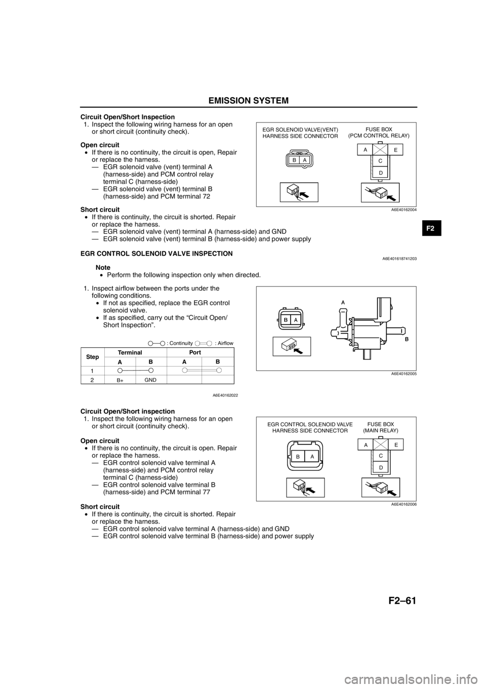
1. Inspect the following wiring harness for an open
or short circuit (continuity check).
Open circuit
•If there is no continuity, the circuit is open, Repair
or replace the harness.
—EGR solenoid valve (vent) terminal A
(harness-side) and PCM control relay
terminal C (harness-side)
—EGR solenoid valve (vent) terminal B
(harness-side) and PCM terminal 72
Short circuit
•If there is continuity, the circuit is shorted. Repair
or replace the harness.
—EGR solenoid valve (vent) terminal A (harness-side) and GND
—EGR solenoid valve (vent) terminal B (harness-side) and power supply
End Of Sie
EGR CONTROL SOLENOID VALVE INSPECTIONA6E401618741203
Note
•Perform the following inspection only when directed.
1. Inspect airflow between the ports under the
following conditions.
•If not as specified, replace the EGR control
solenoid valve.
•If as specified, carry out the “Circuit Open/
Short Inspection”.
Circuit Open/Short inspection
1. Inspect the following wiring harness for an open
or short circuit (continuity check).
Open circuit
•If there is no continuity, the circuit is open. Repair
or replace the harness.
—EGR control solenoid valve terminal A
(harness-side) and PCM control relay
terminal C (harness-side)
—EGR control solenoid valve terminal B
(harness-side) and PCM terminal 77
Short circuit
•If there is continuity, the circuit is shorted. Repair
or replace the harness.
—EGR control solenoid valve terminal A (harness-side) and GND
—EGR control solenoid valve terminal B (harness-side) and power supply
End Of Sie
EGR SOLENOID VALVE(VENT)
HARNESS SIDE CONNECTORFUSE BOX
(PCM CONTROL RELAY)
BAA
C
DE
A6E40162004
B
AA
B
A6E40162005
StepTerminalPor t
: Airflow
ABAB
GND
B+
1
2
: Continuity
A6E40162022
EGR CONTROL SOLENOID VALVE
HARNESS SIDE CONNECTORFUSE BOX
(MAIN RELAY)
BAAE
C
D
A6E40162006
Page 214 of 909
F2–62
EMISSION SYSTEM
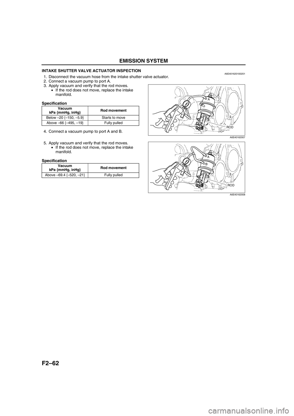
INTAKE SHUTTER VALVE ACTUATOR INSPECTIONA6E4016201002011. Disconnect the vacuum hose from the intake shutter valve actuator.
2. Connect a vacuum pump to port A.
3. Apply vacuum and verify that the rod moves.
•If the rod does not move, replace the intake
manifold.
Specification
4. Connect a vacuum pump to port A and B.
5. Apply vacuum and verify that the rod moves.
•If the rod does not move, replace the intake
manifold.
Specification
End Of Sie
Vacuum
kPa {mmHg, inHg}Rod movement
Below –20 {–150, –5.9} Starts to move
Above –66 {–495, –19} Fully pulled
Vacuum
kPa {mmHg, inHg}Rod movement
Above –69.4 {–520, –21} Fully pulled
A6E40162007
A6E40162008
Page 215 of 909
EMISSION SYSTEM
F2–63
F2
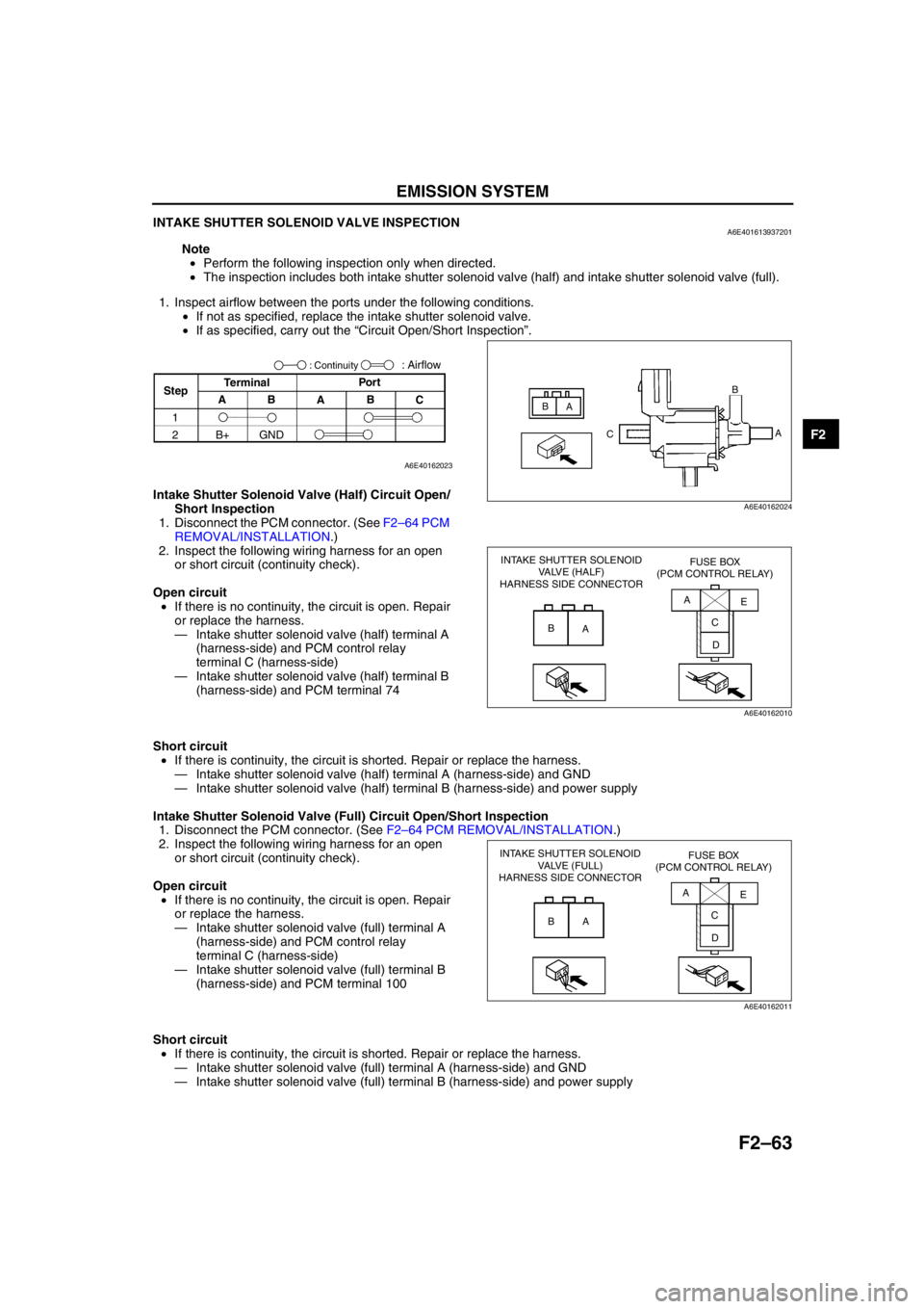
INTAKE SHUTTER SOLENOID VALVE INSPECTIONA6E401613937201
Note
•Perform the following inspection only when directed.
•The inspection includes both intake shutter solenoid valve (half) and intake shutter solenoid valve (full).
1. Inspect airflow between the ports under the following conditions.
•If not as specified, replace the intake shutter solenoid valve.
•If as specified, carry out the “Circuit Open/Short Inspection”.
Intake Shutter Solenoid Valve (Half) Circuit Open/
Short Inspection
1. Disconnect the PCM connector. (See F2–64 PCM
REMOVAL/INSTALLATION.)
2. Inspect the following wiring harness for an open
or short circuit (continuity check).
Open circuit
•If there is no continuity, the circuit is open. Repair
or replace the harness.
—Intake shutter solenoid valve (half) terminal A
(harness-side) and PCM control relay
terminal C (harness-side)
—Intake shutter solenoid valve (half) terminal B
(harness-side) and PCM terminal 74
Short circuit
•If there is continuity, the circuit is shorted. Repair or replace the harness.
—Intake shutter solenoid valve (half) terminal A (harness-side) and GND
—Intake shutter solenoid valve (half) terminal B (harness-side) and power supply
Intake Shutter Solenoid Valve (Full) Circuit Open/Short Inspection
1. Disconnect the PCM connector. (See F2–64 PCM REMOVAL/INSTALLATION.)
2. Inspect the following wiring harness for an open
or short circuit (continuity check).
Open circuit
•If there is no continuity, the circuit is open. Repair
or replace the harness.
—Intake shutter solenoid valve (full) terminal A
(harness-side) and PCM control relay
terminal C (harness-side)
—Intake shutter solenoid valve (full) terminal B
(harness-side) and PCM terminal 100
Short circuit
•If there is continuity, the circuit is shorted. Repair or replace the harness.
—Intake shutter solenoid valve (full) terminal A (harness-side) and GND
—Intake shutter solenoid valve (full) terminal B (harness-side) and power supply
End Of Sie
B
A
CB
A
A6E40162024
StepTerminal
C B
A B APor t: Airflow
1
2B+ GND
: Continuity
A6E40162023
INTAKE SHUTTER SOLENOID
VALVE (HALF)
HARNESS SIDE CONNECTORFUSE BOX
(PCM CONTROL RELAY)
B
AA
E
C
D
A6E40162010
INTAKE SHUTTER SOLENOID
VALVE (FULL)
HARNESS SIDE CONNECTORFUSE BOX
(PCM CONTROL RELAY)
B
AA
C
DE
A6E40162011
Page 216 of 909
F2–64
CONTROL SYSTEM
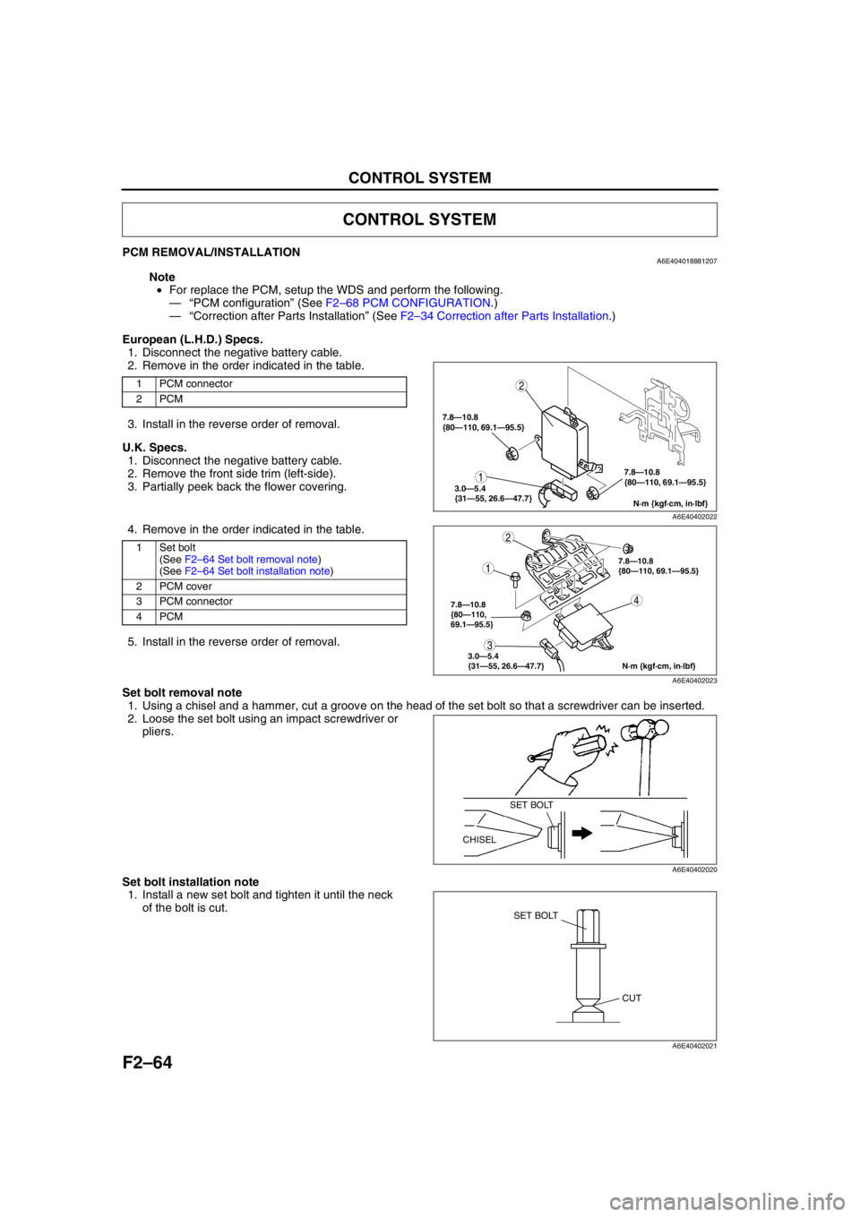
PCM REMOVAL/INSTALLATIONA6E404018881207
Note
•For replace the PCM, setup the WDS and perform the following.
—“PCM configuration” (See F2–68 PCM CONFIGURATION.)
—“Correction after Parts Installation” (See F2–34 Correction after Parts Installation.)
European (L.H.D.) Specs.
1. Disconnect the negative battery cable.
2. Remove in the order indicated in the table.
3. Install in the reverse order of removal.
U.K. Specs.
1. Disconnect the negative battery cable.
2. Remove the front side trim (left-side).
3. Partially peek back the flower covering.
4. Remove in the order indicated in the table.
5. Install in the reverse order of removal.
Set bolt removal note
1. Using a chisel and a hammer, cut a groove on the head of the set bolt so that a screwdriver can be inserted.
2. Loose the set bolt using an impact screwdriver or
pliers.
Set bolt installation note
1. Install a new set bolt and tighten it until the neck
of the bolt is cut.
CONTROL SYSTEM
1 PCM connector
2PCM
1Set bolt
(See F2–64 Set bolt removal note)
(See F2–64 Set bolt installation note)
2 PCM cover
3 PCM connector
4PCM
1
2
N·m {kgf·cm, in·lbf} 7.8—10.8
{80—110, 69.1—95.5}
3.0—5.4
{31—55, 26.6—47.7}
7.8—10.8
{80—110, 69.1—95.5}
A6E40402022
4
1
2
3
N·m {kgf·cm, in·lbf} 7.8—10.8
{80—110,
69.1—95.5}
3.0—5.4
{31—55, 26.6—47.7}
7.8—10.8
{80—110, 69.1—95.5}
A6E40402023
SET BOLT
CHISEL
A6E40402020
SET BOLT
CUT
A6E40402021
Page 217 of 909
CONTROL SYSTEM
F2–65
F2
End Of SiePCM INSPECTIONA6E404018881208Using WDS or Equivalent
Caution
•The PCM terminal voltage vary with change in measuring conditions and vehicle conditions.
Always carry out a total inspection of the input systems, output systems, and PCM to determine
the cause of trouble. Otherwise, diagnosis will be incorrect.
Note
•For replace the PCM, setup the WDS and perform the following.
—“PCM configuration” (See F2–68 PCM CONFIGURATION.)
—“Correction after Parts Installation” (See F2–34 Correction after Parts Installation.)
1. Connect the WDS or equivalent to the DLC-2. (See F2–85 ON-BOARD DIAGNOSTIC TEST.)
2. Turn the engine switch to ON.
3. Measure the PID value.
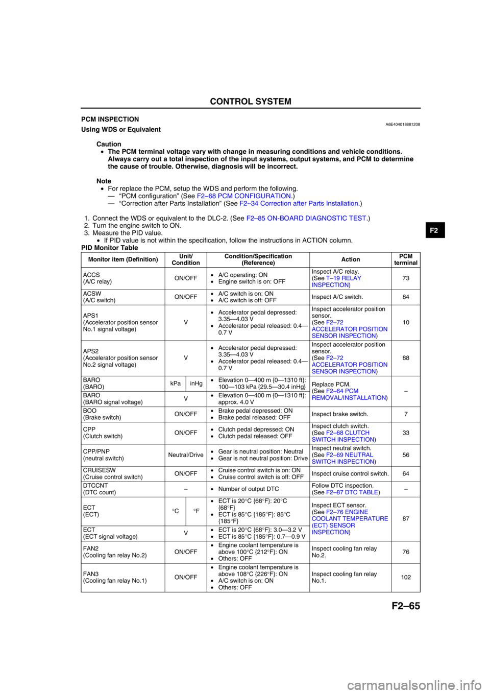
•If PID value is not within the specification, follow the instructions in ACTION column.
PID Monitor Table
Monitor item (Definition)Unit/
ConditionCondition/Specification
(Reference)ActionPCM
terminal
ACCS
(A/C relay)ON/OFF•A/C operating: ON
•Engine switch is on: OFFInspect A/C relay.
(See T–19 RELAY
INSPECTION)73
ACSW
(A/C switch)ON/OFF•A/C switch is on: ON
•A/C switch is off: OFFInspect A/C switch. 84
APS1
(Accelerator position sensor
No.1 signal voltage)V•Accelerator pedal depressed:
3.35—4.03 V
•Accelerator pedal released: 0.4—
0.7 VInspect accelerator position
sensor.
(See F2–72
ACCELERATOR POSITION
SENSOR INSPECTION)10
APS2
(Accelerator position sensor
No.2 signal voltage)V•Accelerator pedal depressed:
3.35—4.03 V
•Accelerator pedal released: 0.4—
0.7 VInspect accelerator position
sensor.
(See F2–72
ACCELERATOR POSITION
SENSOR INSPECTION)88
BARO
(BARO)kPa inHg•Elevation 0—400 m {0—1310 ft}:
100—103 kPa {29.5—30.4 inHg}Replace PCM.
(See F2–64 PCM
REMOVAL/INSTALLATION)–
BARO
(BARO signal voltage)V•Elevation 0—400 m {0—1310 ft}:
approx. 4.0 V
BOO
(Brake switch)ON/OFF•Brake pedal depressed: ON
•Brake pedal released: OFFInspect brake switch. 7
CPP
(Clutch switch)ON/OFF•Clutch pedal depressed: ON
•Clutch pedal released: OFFInspect clutch switch.
(See F2–68 CLUTCH
SWITCH INSPECTION)33
CPP/PNP
(neutral switch)Neutral/Drive•Gear is neutral position: Neutral
•Gear is not neutral position: DriveInspect neutral switch.
(See F2–69 NEUTRAL
SWITCH INSPECTION)56
CRUISESW
(Cruise control switch)ON/OFF•Cruise control switch is on: ON
•Cruise control switch is off: OFFInspect cruise control switch. 64
DTCCNT
(DTC count)–•Number of output DTCFollow DTC inspection.
(See F2–87 DTC TABLE)–
ECT
(ECT)°C°F•ECT is 20°C {68°F}: 20°C
{68°F}
•ECT is 85°C {185°F}: 85°C
{185°F}Inspect ECT sensor.
(See F2–76 ENGINE
COOLANT TEMPERATURE
(ECT) SENSOR
INSPECTION)87
ECT
(ECT signal voltage)V•ECT is 20°C {68°F}: 3.0—3.2 V
•ECT is 85°C {185°F}: 0.7—0.9 V
FAN2
(Cooling fan relay No.2)ON/OFF•Engine coolant temperature is
above 100°C {212°F}: ON
•Others: OFFInspect cooling fan relay
No.2.76
FAN3
(Cooling fan relay No.1)ON/OFF•Engine coolant temperature is
above 108°C {226°F}: ON
•A/C switch is on: ON
•Others: OFFInspect cooling fan relay
No.1.102
Page 218 of 909
F2–66
CONTROL SYSTEM
IAT
(IAT)°C°F•IAT is 20°C {68°F}: 20°C {68°F}
•IAT is 30°C {86°F}: 30°C {86°F}Inspect IAT sensor No.1.
(See F2–74 MASS AIR
FLOW (MAF)/INTAKE AIR
TEMPERATURE (IAT)
SENSOR INSPECTION)60
IAT
(IAT signal voltage)V•IAT is 20°C {68°F}: 2.2—2.5 V
•IAT is 30°C {86°F}: 1.7—2.0 V
IMRC
(VSC solenoid valve)ON/OFF•Idle: ON
•Engine speed is above approx.
2,500 rpm: OFFInspect following PIDs:
BARO, ECT, IAT, RPM, VSS101
INGEAR
(In gear)ON/OFF•Gear is not neutral position and
clutch pedal released: ON
•Gear is neutral position: OFF
•Clutch pedal depressed: OFFInspect following PIDs:
CPP, CPP/PNP33, 56
INJ_LRN_DIS
(Distance from the last
injector learning)Km Mile•Distance from the last injector
learning––
MAF
(Mass air flow amount)g/s•Engine switch is on: approx. 0 g/s
•Idle: 6.8—7.4 g/sInspect MAF/IAT sensor.
(See F2–74 MASS AIR
FLOW (MAF)/INTAKE AIR
TEMPERATURE (IAT)
SENSOR INSPECTION)9
MAF
(Mass air flow signal voltage)V•Engine switch is on: 0.0—1.0 V
•Idle: 1.5—2.1 V
MAF_LRN_DIS
(Distance from the last MAF
learning)Km Mile•Distance from the last MAF
learning––
MAINRLY
(PCM control relay)ON/OFF•Engine switch is on: ONInspect PCM control relay.
(See T–19 RELAY
INSPECTION)69
MAP
(MAP)kPa inHg•Engine switch is on: 100—103
kPa {29.5—30.4 inHg}
•Idle: 100—103 kPa {29.5—30.4
inHg}Inspect boost sensor.
(See F2–78 BOOST
SENSOR INSPECTION)36
MAP
(MAP signal voltage)V•Engine switch is on: 2.1—2.5 V
•Idle: 2.1—2.5 V
MIL
(MIL)ON/OFF•Engine switch is on: ON
•DTC output: ON
•Others: OFFInspect instrument cluster.
Inspect CAN system.
(See T–39 MULTIPLEX
COMMUNICATION
SYSTEM)13, 39
NUMKEYS
(Number of keys stored in
module)–•Number of keys stored in module––
RPM
(Engine speed)rpm•Idle: 725—825 rpmInspect CKP sensor.
(See F2–80 CAMSHAFT
POSITION (CMP) SENSOR
INSPECTION)3, 29
VPWR
(Battery positive voltage)V•Engine switch is ON: B+Inspect Battery.
Inspect fuse.4
VSS
(Vehicle speed)km/h mph•Vehicle speed is 20 km/h {12.5
mph}: 20 km/h {12.5 mph}
•Vehicle speed is 40 km/h {25
mph}: 40 km/h {25 mph}Inspect CAN system.
(See T–39 MULTIPLEX
COMMUNICATION
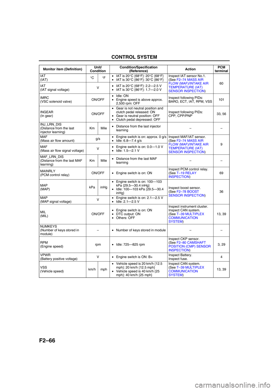
SYSTEM)13, 39 Monitor item (Definition)Unit/
ConditionCondition/Specification
(Reference)ActionPCM
terminal
Page 219 of 909
CONTROL SYSTEM
F2–67
F2
Not Using WDS or Equivalent
Constant voltage terminal inspection
1. Turn the engine switch to ON.
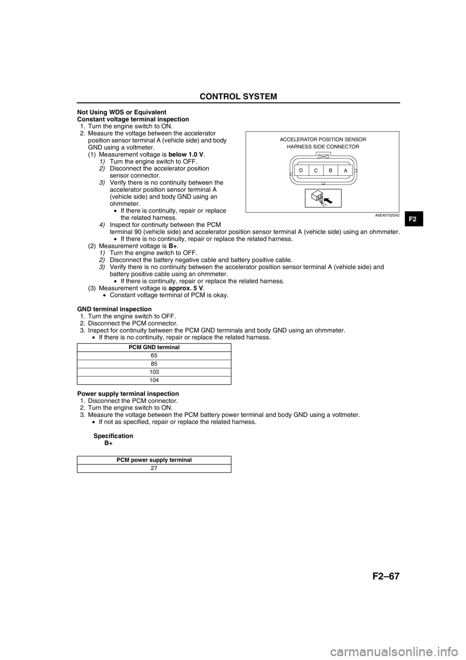
2. Measure the voltage between the accelerator
position sensor terminal A (vehicle side) and body
GND using a voltmeter.
(1) Measurement voltage is below 1.0 V.
1)Turn the engine switch to OFF.
2)Disconnect the accelerator position
sensor connector.
3)Verify there is no continuity between the
accelerator position sensor terminal A
(vehicle side) and body GND using an
ohmmeter.
•If there is continuity, repair or replace
the related harness.
4)Inspect for continuity between the PCM
terminal 90 (vehicle side) and accelerator position sensor terminal A (vehicle side) using an ohmmeter.
•If there is no continuity, repair or replace the related harness.
(2) Measurement voltage is B+.
1)Turn the engine switch to OFF.
2)Disconnect the battery negative cable and battery positive cable.
3)Verify there is no continuity between the accelerator position sensor terminal A (vehicle side) and
battery positive cable using an ohmmeter.
•If there is continuity, repair or replace the related harness.
(3) Measurement voltage is approx. 5 V.
•Constant voltage terminal of PCM is okay.
GND terminal inspection
1. Turn the engine switch to OFF.
2. Disconnect the PCM connector.
3. Inspect for continuity between the PCM GND terminals and body GND using an ohmmeter.
•If there is no continuity, repair or replace the related harness.
Power supply terminal inspection
1. Disconnect the PCM connector.
2. Turn the engine switch to ON.
3. Measure the voltage between the PCM battery power terminal and body GND using a voltmeter.
•If not as specified, repair or replace the related harness.
Specification
B+
End Of Sie
ACCELERATOR POSITION SENSOR
HARNESS SIDE CONNECTOR
A B
C D
A6E40702042
PCM GND terminal
65
85
103
104
PCM power supply terminal
27
Page 220 of 909
F2–68
CONTROL SYSTEM
PCM CONFIGURATIONA6E4040188812091. Connect the WDS to DLC-2.
2. Set up the WDS (including the vehicle
recognition).
3. Select “Module programming.”
4. Select “Programmable module installation.”
5. Select “PCM” and perform procedures according
to directions on the WDS screen.
Note
•If the PCM is replaced with a new one, the
PCM stores DTC P0602 and illuminates the
MIL even though no malfunction is detected.
After completing the "PCM
CONFIGURATION" procedure, clear DTC
P0602 using the WDS or equivalent.
6. Retrieve DTC’s by the WDS or equivalent, then verify that there in no DTC present.
•If DTC is present, perform applicable DTC inspection.
End Of Sie
CLUTCH SWITCH INSPECTIONA6E404018660201
Note
•Perform the following test only when directed.
Continuity Inspection
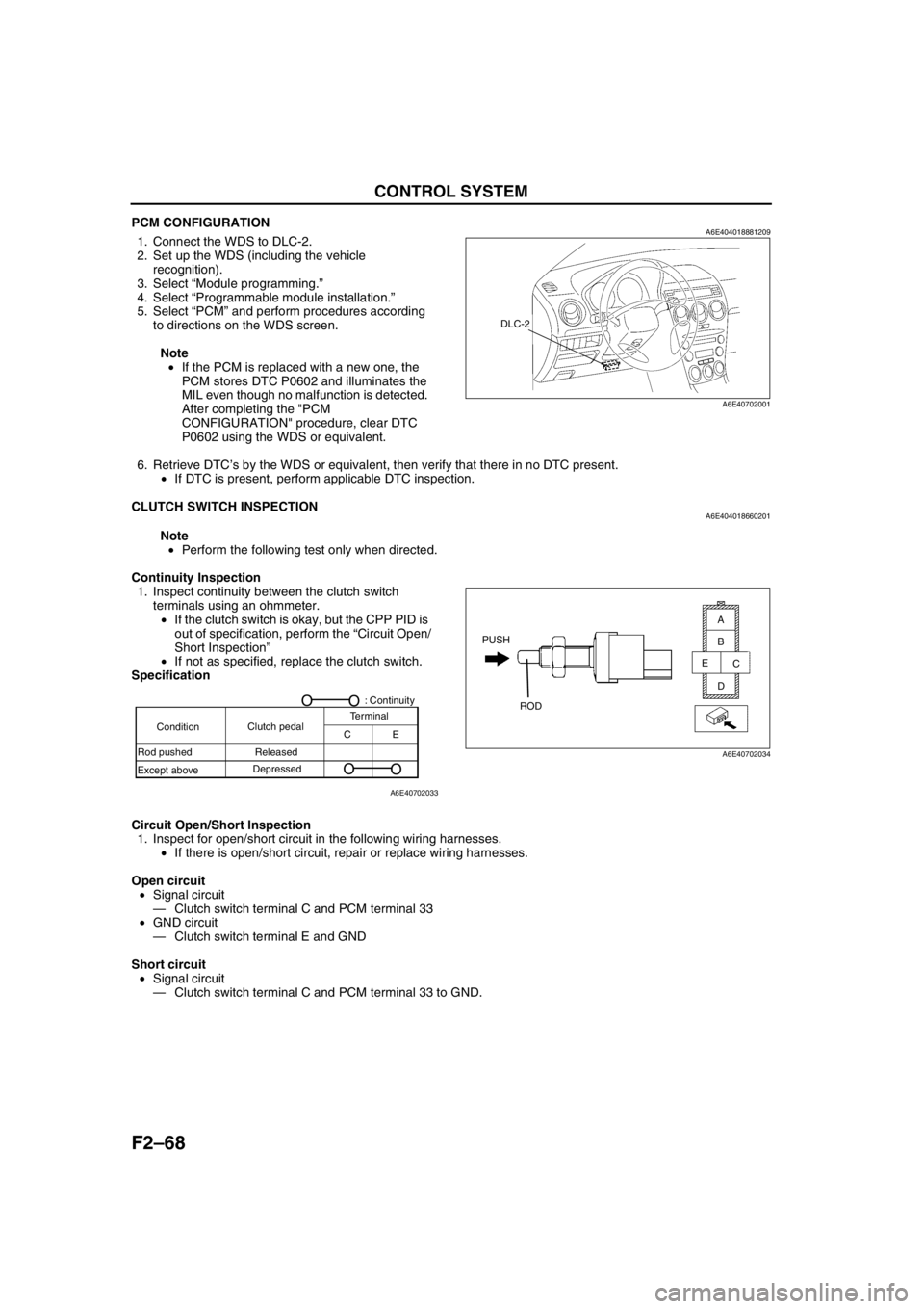
1. Inspect continuity between the clutch switch
terminals using an ohmmeter.
•If the clutch switch is okay, but the CPP PID is
out of specification, perform the “Circuit Open/
Short Inspection”
•If not as specified, replace the clutch switch.
Specification
Circuit Open/Short Inspection
1. Inspect for open/short circuit in the following wiring harnesses.
•If there is open/short circuit, repair or replace wiring harnesses.
Open circuit
•Signal circuit
—Clutch switch terminal C and PCM terminal 33
•GND circuit
—Clutch switch terminal E and GND
Short circuit
•Signal circuit
—Clutch switch terminal C and PCM terminal 33 to GND.
End Of Sie
DLC-2
A6E40702001
PUSH
ROD
A
B
C
D E
A6E40702034
A6E40702033
ConditionClutch pedalTerminal
CE
Rod pushed
Except aboveReleased
Depressed
O
O
O
O: Continuity