lock MAZDA 6 2002 Suplement Repair Manual
[x] Cancel search | Manufacturer: MAZDA, Model Year: 2002, Model line: 6, Model: MAZDA 6 2002Pages: 909, PDF Size: 17.16 MB
Page 625 of 909
PROPELLER SHAFT
L–9
L
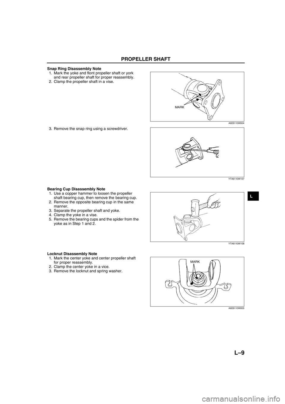
Snap Ring Disassembly Note
1. Mark the yoke and flont propeller shaft or york
and rear propeller shaft for proper reassembly.
2. Clamp the propeller shaft in a vise.
3. Remove the snap ring using a screwdriver.
Bearing Cup Disassembly Note
1. Use a copper hammer to loosen the propeller
shaft bearing cup, then remove the bearing cup.
2. Remove the opposite bearing cup in the same
manner.
3. Separate the propeller shaft and yoke.
4. Clamp the yoke in a vise.
5. Remove the bearing cups and the spider from the
yoke as in Step 1 and 2.
Locknut Disassembly Note
1. Mark the center yoke and center propeller shaft
for proper reassembly.
2. Clamp the center yoke in a vice.
3. Remove the locknut and spring washer.
MARK
A6E6110W004
YTA6110W107
YTA6110W108
MARK
A6E6110W005
Page 628 of 909
L–12
PROPELLER SHAFT
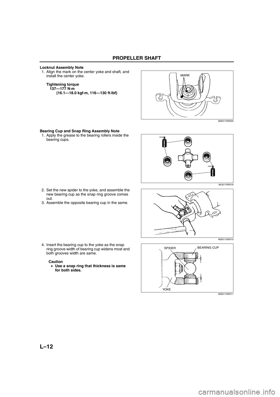
Locknut Assembly Note
1. Align the mark on the center yoke and shaft, and
install the center yoke.
Tightening torque
137—177 N·m
{16.1—18.0 kgf·m, 116—130 ft·lbf}
Bearing Cup and Snap Ring Assembly Note
1. Apply the grease to the bearing rollers inside the
bearing cups.
2. Set the new spider to the yoke, and assemble the
new bearing cup as the snap ring groove comes
out.
3. Assemble the opposite bearing cup in the same.
4. Insert the bearing cup to the yoke as the snap
ring groove width of bearing cup widens most and
both grooves width are same.
Caution
•Use a snap ring that thickness is same
for both sides.
MARK
A6E6110W005
GREASEGREASE
GREASEGREASE
A6J6110W016
A6E6110W010
BEARING CUPSPIDER
YOKE
A6E6110W011
Page 643 of 909
ELECTRONIC 4WD CONTROL SYSTEM
M–13
M
4WD CONTROL MODUREA6E632227100205Function
•The 4WD control modure (4WD CM) calculates the optimal amount of torque distribution for the rear wheels
and outputs a corresponding electric current to the electronic control coupling (4WD solenoid). This calculation
is based on the throttle angle, four-wheel speed, engine speed, selector lever position, and other related input
signals, matched with the vehicle driving and road surface conditions.
Functions
Construction
•The 4WD CM is installed to the left of the brake pedal (clutch pedal position).
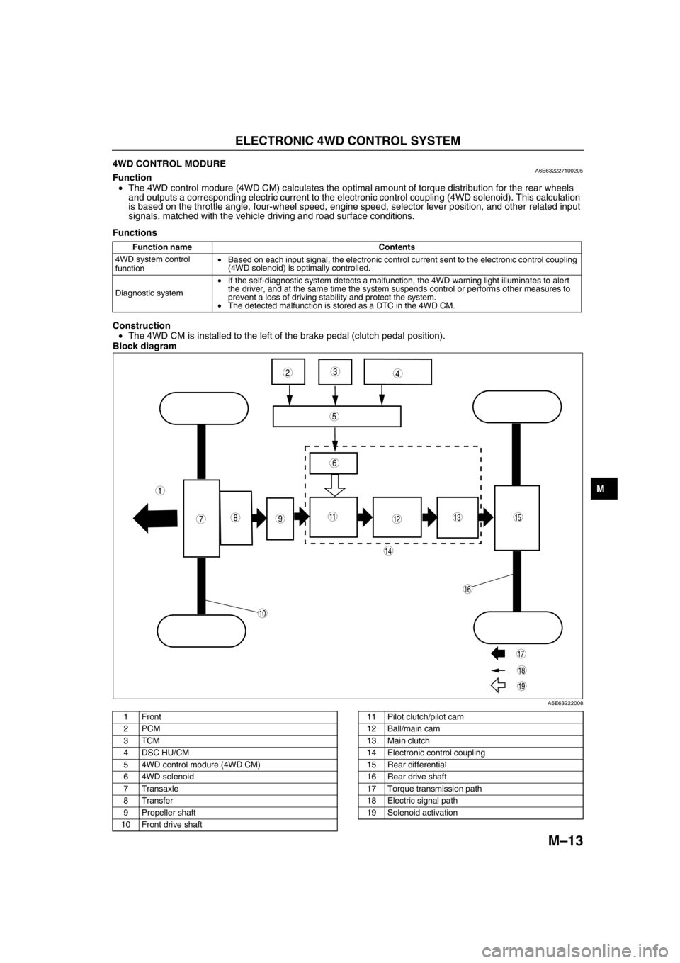
Block diagram
.
Function name Contents
4WD system control
function•Based on each input signal, the electronic control current sent to the electronic control coupling
(4WD solenoid) is optimally controlled.
Diagnostic system•If the self-diagnostic system detects a malfunction, the 4WD warning light illuminates to alert
the driver, and at the same time the system suspends control or performs other measures to
prevent a loss of driving stability and protect the system.
•The detected malfunction is stored as a DTC in the 4WD CM.
987
5
43
10
19
18
17
15
16
14
131112
6
1
2
A6E63222008
1Front
2PCM
3TCM
4 DSC HU/CM
5 4WD control modure (4WD CM)
6 4WD solenoid
7Transaxle
8Transfer
9 Propeller shaft
10 Front drive shaft11 Pilot clutch/pilot cam
12 Ball/main cam
13 Main clutch
14 Electronic control coupling
15 Rear differential
16 Rear drive shaft
17 Torque transmission path
18 Electric signal path
19 Solenoid activation
Page 644 of 909
M–14
ELECTRONIC 4WD CONTROL SYSTEM
End Of Sie4WD SYSTEM CONTROLA6E632227100206Outline
Features
•Based on the inputted signals listed below, the 4WD CM calculates the optimal amount of torque distribution for
the rear wheels and outputs a corresponding electric control current to the electronic control coupling (4WD
solenoid).
•The module controls the current outputted to the 4WD solenoid by changing the rate of the ON/OFF timing.
Construction
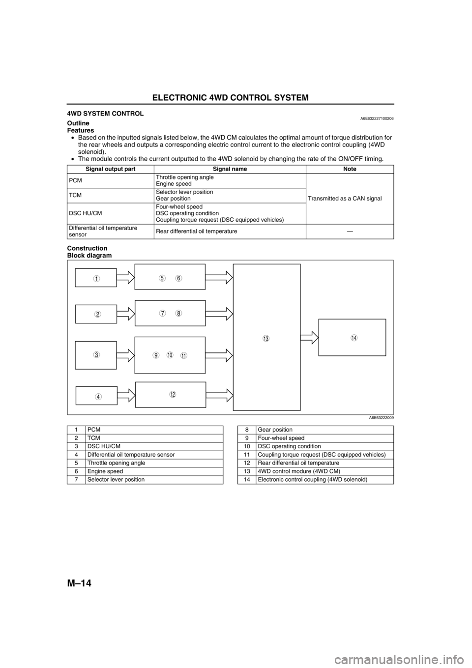
Block diagram
.
Signal output part Signal name Note
PCMThrottle opening angle
Engine speed
Transmitted as a CAN signal TCMSelector lever position
Gear position
DSC HU/CMFour-wheel speed
DSC operating condition
Coupling torque request (DSC equipped vehicles)
Differential oil temperature
sensorRear differential oil temperature—
9
87
5
4
310
1413
11
12
61
2
A6E63222009
1PCM
2TCM
3 DSC HU/CM
4 Differential oil temperature sensor
5 Throttle opening angle
6 Engine speed
7 Selector lever position8 Gear position
9 Four-wheel speed
10 DSC operating condition
11 Coupling torque request (DSC equipped vehicles)
12 Rear differential oil temperature
13 4WD control modure (4WD CM)
14 Electronic control coupling (4WD solenoid)
Page 646 of 909
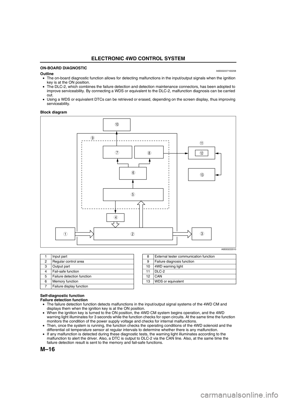
M–16
ELECTRONIC 4WD CONTROL SYSTEM
ON-BOARD DIAGNOSTICA6E632227100208Outline
•The on-board diagnostic function allows for detecting malfunctions in the input/output signals when the ignition
key is at the ON position.
•The DLC-2, which combines the failure detection and detection maintenance connectors, has been adopted to
improve serviceability. By connecting a WDS or equivalent to the DLC-2, malfunction diagnosis can be carried
out.
•Using a WDS or equivalent DTCs can be retrieved or erased, depending on the screen display, thus improving
serviceability.
Block diagram
.
Self-diagnostic function
Failure detection function
•The failure detection function detects malfunctions in the input/output signal systems of the 4WD CM and
displays them when the ignition key is at the ON position.
•When the ignition key is turned to the ON position, the 4WD CM system begins operation, and the 4WD
warning light illuminates for 3 seconds while the function checks for open circuits. At the same time the function
monitors the condition of the power supply voltage and checks for internal malfunctions.
•Then, once the system is running, the function checks the operating conditions of the 4WD solenoid and the
differential oil temperature sensor at regular intervals to determine whether there is any malfunction.
•If any malfunction is detected during these diagnostic tests, the warning light illuminates according to the
malfunction to alert the driver. Also, a DTC is output to DLC-2 via the CAN line. Also, at the same time the
failure detection result is sent to the memory and fail-safe functions.
9
87
5
4
3
10
13
11
12
6
12
A6E63222010
1 Input part
2 Regular control area
3 Output part
4 Fail-safe function
5 Failure detection function
6 Memory function
7 Failure display function8 External tester communication function
9 Failure diagnosis function
10 4WD warning light
11 DLC-2
12 CAN
13 WDS or equivalent
Page 647 of 909
ELECTRONIC 4WD CONTROL SYSTEM
M–17
M
Memory function
•This function stores DTCs for malfunctions of the input/output signal systems as determined by the failure
detection function. Once a DTC is stored, it is not cleared even if the input/output signal system malfunction
returns to normal when the ignition key is turned to the LOCK position (engine OFF).
•Since DTCs are stored in the non-volatile memory inside the 4WD CM, they are not cleared even if the battery
is disconnected. Therefore, it is necessary to clear the memory when maintenance has been completed. For
clearing DTCs, refer to the procedures in the Workshop Manual.
•When inspecting DTCs using a WDS or equivalent, only one memory stored DTC at a time can be displayed.
Therefore, when multiple DTCs have been stored, it is necessary to inspect for DTCs again after repairing and
clearing the present DTC to ensure that there are no more DTCs present in the memory.
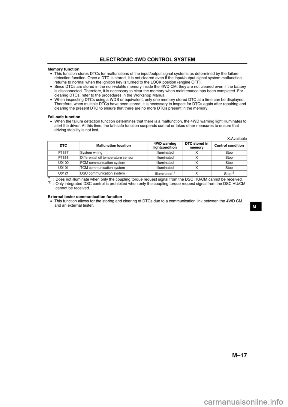
Fail-safe function
•When the failure detection function determines that there is a malfunction, the 4WD warning light illuminates to
alert the driver. At this time, the fail-safe function suspends control or takes other measures to ensure that
driving stability is not lost.
X:Available
*1: Does not illuminate when only the coupling torque request signal from the DSC HU/CM cannot be received.*2: Only integrated DSC control is prohibited when only the coupling torque request signal from the DSC HU/CM
cannot be received.
External tester communication function
•This function allows for the storing and clearing of DTCs due to a communication link between the 4WD CM
and an external tester.
End Of Sie
DTC Malfunction location4WD warning
lightconditionDTC stored in
memoryControl condition
P1887 System wiring Illuminated X Stop
P1888 Differential oil temperature sensor Illuminated X Stop
U0100 PCM communication system Illuminated X Stop
U0101 TCM communication system Illuminated X Stop
U0121 DSC communication system
Illuminated
*1X
Stop*2
Page 653 of 909
REAR AXLE
M–23
M
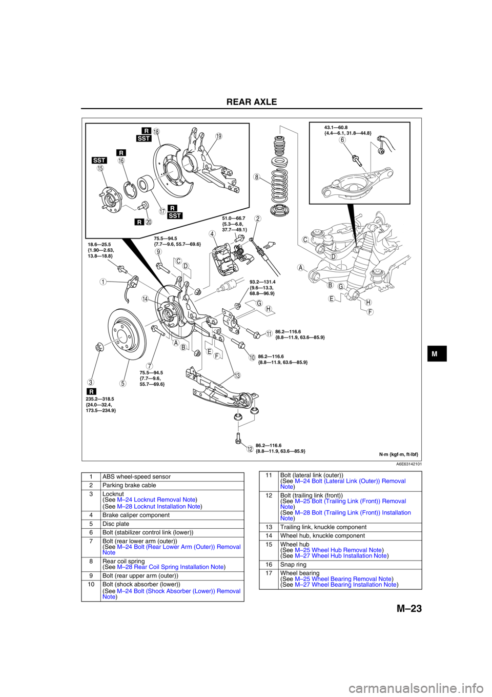
.
93.2—131.4
{9.6—13.3,
68.8—96.9}
HHG
G
E
E
F
F
AB
A
B
C
C
D
D
86.2—116.6
{8.8—11.9, 63.6—85.9} 18.6—25.5
{1.90—2.63,
13.8—18.8}75.5—94.5
{7.7—9.6, 55.7—69.6}51.0—66.7
{5.3—6.8,
37.7—49.1}43.1—60.8
{4.4—6.1, 31.8—44.8}
235.2—318.5
{24.0—32.4,
173.5—234.9}
9
8
7
5
4
3
1
2
10
1918
17
15
16
14
13
11
12
20
6SST
SST
R
SST
R
R
R
R
75.5—94.5
{7.7—9.6,
55.7—69.6}
86.2—116.6
{8.8—11.9, 63.6—85.9}
86.2—116.6
{8.8—11.9, 63.6—85.9}
N·m {kgf·m, ft·lbf}
A6E63142101
1 ABS wheel-speed sensor
2 Parking brake cable
3 Locknut
(See M–24 Locknut Removal Note)
(See M–28 Locknut Installation Note)
4 Brake caliper component
5 Disc plate
6 Bolt (stabilizer control link (lower))
7 Bolt (rear lower arm (outer))
(See M–24 Bolt (Rear Lower Arm (Outer)) Removal
Note
8 Rear coil spring
(See M–28 Rear Coil Spring Installation Note)
9 Bolt (rear upper arm (outer))
10 Bolt (shock absorber (lower))
(See M–24 Bolt (Shock Absorber (Lower)) Removal
Note)11 Bolt (lateral link (outer))
(See M–24 Bolt (Lateral Link (Outer)) Removal
Note)
12 Bolt (trailing link (front))
(See M–25 Bolt (Trailing Link (Front)) Removal
Note)
(See M–28 Bolt (Trailing Link (Front)) Installation
Note)
13 Trailing link, knuckle component
14 Wheel hub, knuckle component
15 Wheel hub
(See M–25 Wheel Hub Removal Note)
(See M–27 Wheel Hub Installation Note)
16 Snap ring
17 Wheel bearing
(See M–25 Wheel Bearing Removal Note)
(See M–27 Wheel Bearing Installation Note)
Page 654 of 909
M–24
REAR AXLE
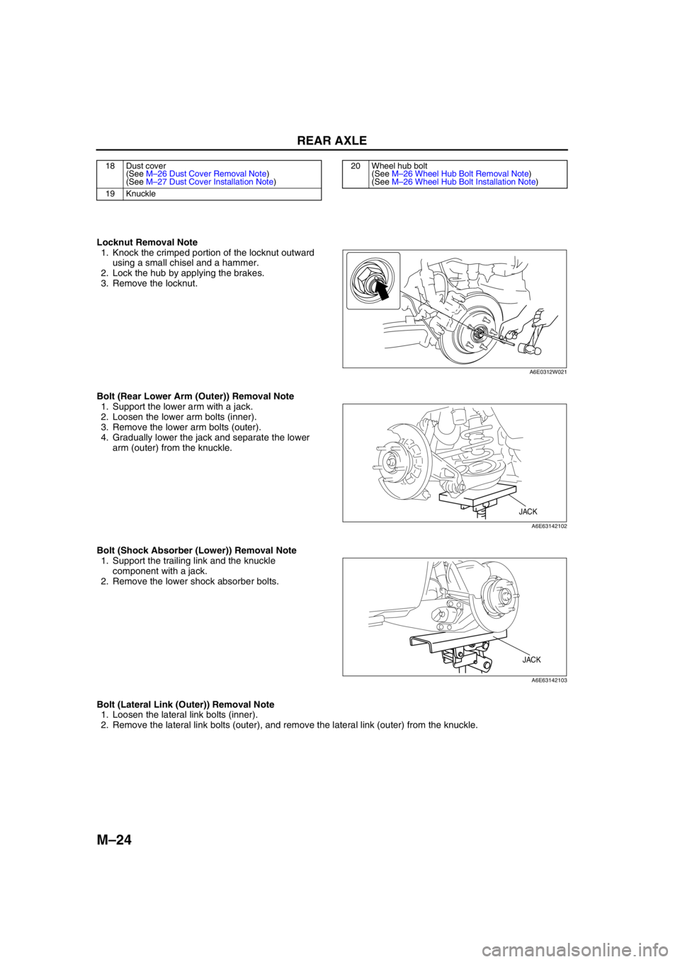
Locknut Removal Note
1. Knock the crimped portion of the locknut outward
using a small chisel and a hammer.
2. Lock the hub by applying the brakes.
3. Remove the locknut.
Bolt (Rear Lower Arm (Outer)) Removal Note
1. Support the lower arm with a jack.
2. Loosen the lower arm bolts (inner).
3. Remove the lower arm bolts (outer).
4. Gradually lower the jack and separate the lower
arm (outer) from the knuckle.
Bolt (Shock Absorber (Lower)) Removal Note
1. Support the trailing link and the knuckle
component with a jack.
2. Remove the lower shock absorber bolts.
Bolt (Lateral Link (Outer)) Removal Note
1. Loosen the lateral link bolts (inner).
2. Remove the lateral link bolts (outer), and remove the lateral link (outer) from the knuckle.
18 Dust cover
(See M–26 Dust Cover Removal Note)
(See M–27 Dust Cover Installation Note)
19 Knuckle20 Wheel hub bolt
(See M–26 Wheel Hub Bolt Removal Note)
(See M–26 Wheel Hub Bolt Installation Note)
A6E0312W021
JACK
A6E63142102
JACK
A6E63142103
Page 658 of 909
M–28
REAR AXLE
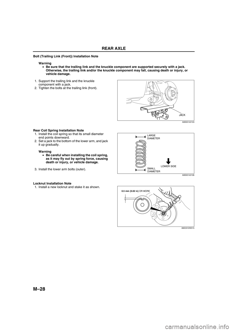
Bolt (Trailing Link (Front)) Installation Note
Warning
•Be sure that the trailing link and the knuckle component are supported securely with a jack.
Otherwise, the trailing link and/or the knuckle component may fall, causing death or injury, or
vehicle damage.
1. Support the trailing link and the knuckle
component with a jack.
2. Tighten the bolts at the trailing link (front).
Rear Coil Spring Installation Note
1. Install the coil spring so that its small diameter
end points downward.
2. Set a jack to the bottom of the lower arm, and jack
it up gradually.
Warning
•Be careful when installing the coil spring,
as it may fly out by spring force, causing
death or injury, or vehicle damage.
3. Install the lower arm bolts (outer).
Locknut Installation Note
1. Install a new locknut and stake it as shown.
End Of Sie
JACK
A6E63142103
LOWER SIDE LARGE
DIAMETER
SMALL
DIAMETER
A6E63142106
0.5 mm {0.02 in} OR MORE
A6E0312W015
Page 665 of 909
FRONT DRIVE SHAFT
M–35
M
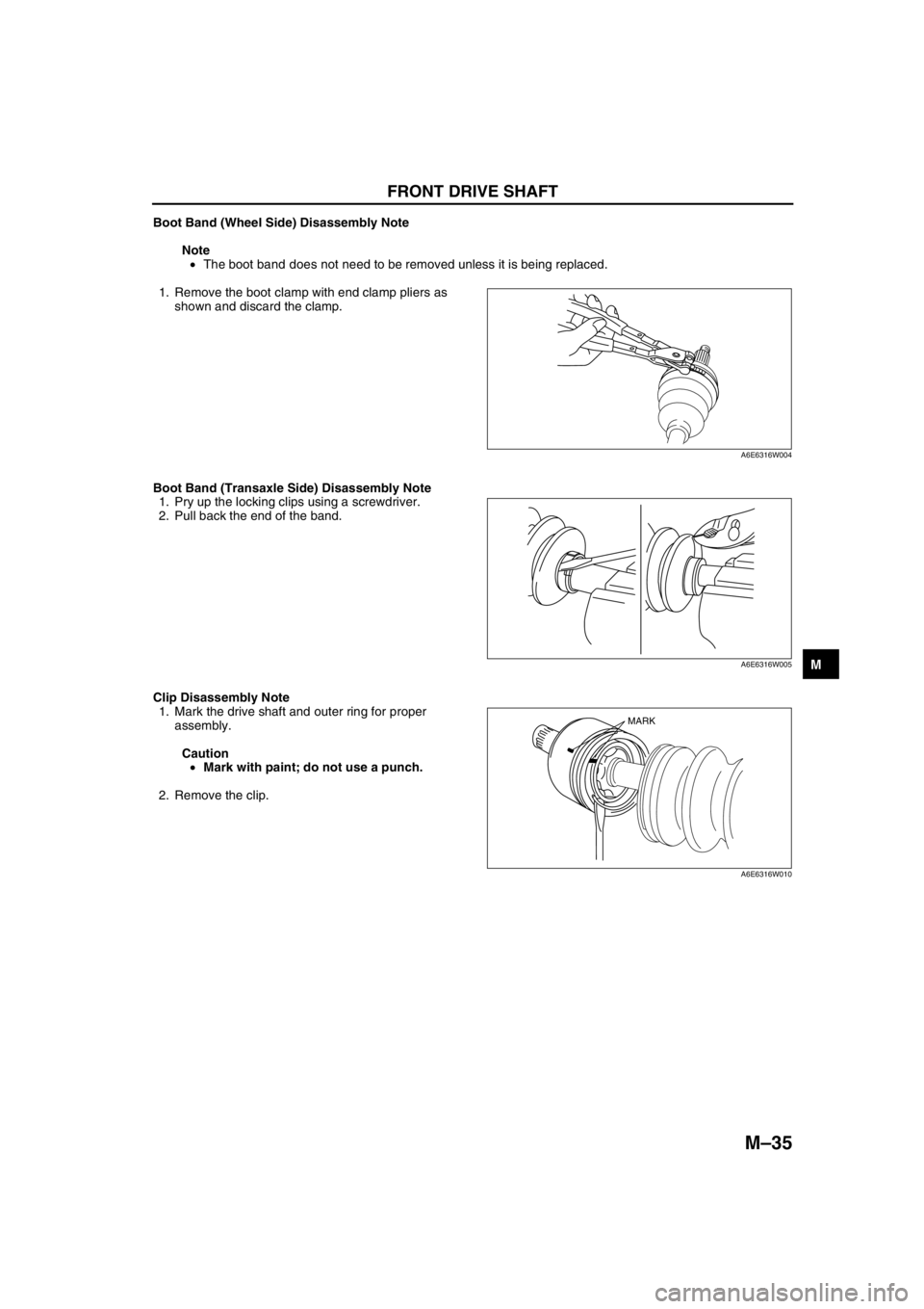
Boot Band (Wheel Side) Disassembly Note
Note
•The boot band does not need to be removed unless it is being replaced.
1. Remove the boot clamp with end clamp pliers as
shown and discard the clamp.
Boot Band (Transaxle Side) Disassembly Note
1. Pry up the locking clips using a screwdriver.
2. Pull back the end of the band.
Clip Disassembly Note
1. Mark the drive shaft and outer ring for proper
assembly.
Caution
•Mark with paint; do not use a punch.
2. Remove the clip.
A6E6316W004
A6E6316W005
MARK
A6E6316W010