engine MAZDA 6 2002 Workshop Manual Suplement
[x] Cancel search | Manufacturer: MAZDA, Model Year: 2002, Model line: 6, Model: MAZDA 6 2002Pages: 909, PDF Size: 17.16 MB
Page 495 of 909
K2–80
AUTOMATIC TRANSAXLE
AUTOMATIC TRANSAXLE FLUID (ATF) REPLACEMENTA6E571419001202
Warning
•When the transaxle and ATF are hot, they can badly burn you. Turn off the engine and wait until
they are cool before changing the ATF.
1. Remove the oil dipstick.
2. Remove the oil drain plug and washer.
3. Drain the ATF into a container.
4. Install a new washer and the drain plug.
Tightening torque
39—54 N·m {3.9—5.6 kgf·m, 29—40 ft·lbf}
5. Add the specified type of ATF through the oil filler
tube, until ATF level reaches lower notch of
dipstick.
ATF type
ATF M-III or equivalent (e.g. Dexron
®III)
Capacity (Approximate quantity)
8.3 L {8.8 US qt, 7.3 Imp qt}
6. Verify that the ATF level is in the HOT (65 °C {149 °F}) range.
•Add ATF to the specified level as necessary.
End Of Sie
TRANSAXLE RANGE (TR) SWITCH INSPECTIONA6E571419440201
Note
•Input signals of the TR switch can be inspected with a WDS or equivalent. (See K2–90 TCM
INSPECTION.)
Inspection of Operation
1. Verify that the starter operates only with the ignition switch at the START position and the selector lever in P
and N positions.
•If not as specified, inspect for continuity at the TR switch. (See K2–80 Inspection of Continuity.)
2. Verify that the back-up lights illuminate when shifted to R position with the ignition switch at the ON position.
•If not as specified, inspect for continuity at the TR switch.
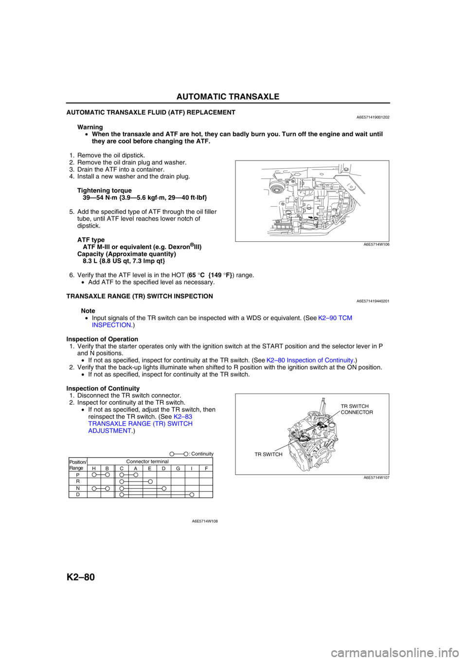
Inspection of Continuity
1. Disconnect the TR switch connector.
2. Inspect for continuity at the TR switch.
•If not as specified, adjust the TR switch, then
reinspect the TR switch. (See K2–83
TRANSAXLE RANGE (TR) SWITCH
ADJUSTMENT.)
A6E5714W106
TR SWITCHTR SWITCH
CONNECTOR
A6E5714W107
Position/
Range
H
P
R
N
DBCAEDGI FConnector terminal: Continuity
A6E5714W108
Page 499 of 909
K2–84
AUTOMATIC TRANSAXLE
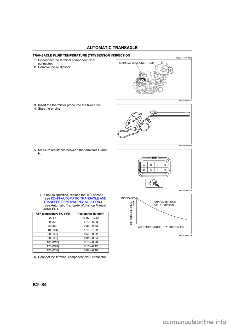
TRANSAXLE FLUID TEMPERATURE (TFT) SENSOR INSPECTIONA6E5714190102021. Disconnect the terminal component No.2
connector.
2. Remove the oil dipstick.
3. Insert the thermistor probe into the filler tube.
4. Start the engine.
5. Measure resistance between the terminals G and
H.
•If not as specified, replace the TFT sensor.
(See K2–99 AUTOMATIC TRANSAXLE AND
TRANSFER REMOVAL/INSTALLATION.)
(See Automatic Transaxle Workshop Manual
JA5A-EL.)
6. Connect the terminal component No.2 connector.
End Of Sie
ATF temperature (°C {°F}) Resistance (kilohm)
-20 {-4} 15.87—17.54
0 {32} 5.73—6.33
20 {68} 2.38—2.63
40 {104} 1.10—1.22
60 {140} 0.56—0.62
80 {176} 0.31—0.34
100 {212} 0.18—0.20
120 {248} 0.11—0.12
130 {266} 0.09—0.10
TERMINAL COMPONENT No.2
A6E5714W117
A6E5614W003
ACEG
BDFH
A6E5714W118
INCREASES
RESISTANCE (ohm)
ATF TEMPERATURE INCREASESCHARACTERISTIC
OF TFT SENSOR
A6E5714W119
Page 505 of 909
K2–90
AUTOMATIC TRANSAXLE
SOLENOID VALVE REMOVAL/INSTALLATIONA6E5714212802031. Remove the control valve body. (See K2–105 CONTROL VALVE BODY REMOVAL/INSTALLATION.)
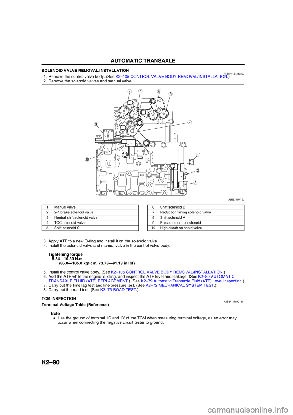
2. Remove the solenoid valves and manual valve.
.
3. Apply ATF to a new O-ring and install it on the solenoid valve.
4. Install the solenoid valve and manual valve in the control valve body.
Tightening torque
8.34—10.30 N·m
{85.0—105.0 kgf·cm, 73.78—91.13 in·lbf}
5. Install the control valve body. (See K2–105 CONTROL VALVE BODY REMOVAL/INSTALLATION.)
6. Add the ATF while the engine is idling, and inspect the ATF level and leakage. (See K2–80 AUTOMATIC
TRANSAXLE FLUID (ATF) REPLACEMENT.) (See K2–79 Automatic Transaxle Fluid (ATF) Level Inspection.)
7. Carry out the time lag test and line pressure test. (See K2–72 MECHANICAL SYSTEM TEST.)
8. Carry out the road test. (See K2–75 ROAD TEST.)
End Of Sie
TCM INSPECTIONA6E571418901211Terminal Voltage Table (Reference)
Note
•Use the ground of terminal 1C and 1Y of the TCM when measuring terminal voltage, as an error may
occur when connecting the negative circuit tester to ground.
5
44
3
10
687
9
1
2
A6E5714W122
1 Manual valve
2 2-4 brake solenoid valve
3 Neutral shift solenoid valve
4 TCC solenoid valve
5 Shift solenoid C6 Shift solenoid B
7 Reduction timing solenoid valve
8 Shift solenoid A
9 Pressure control solenoid
10 High clutch solenoid valve
Page 516 of 909
AUTOMATIC TRANSAXLE
K2–101
K2
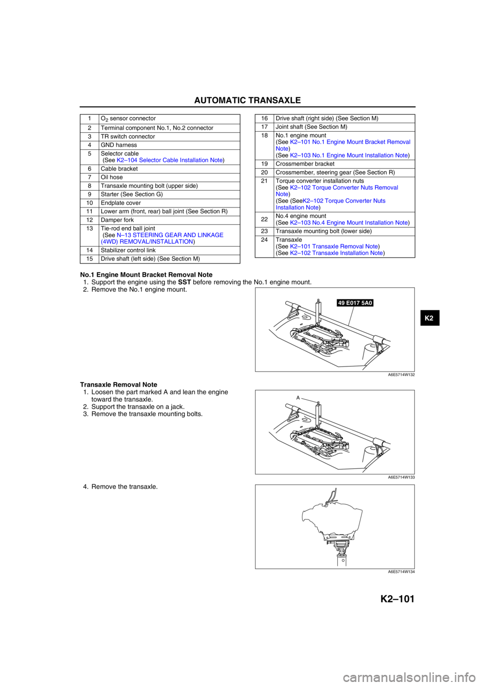
No.1 Engine Mount Bracket Removal Note
1. Support the engine using the SST before removing the No.1 engine mount.
2. Remove the No.1 engine mount.
Transaxle Removal Note
1. Loosen the part marked A and lean the engine
toward the transaxle.
2. Support the transaxle on a jack.
3. Remove the transaxle mounting bolts.
4. Remove the transaxle.
1O2 sensor connector
2 Terminal component No.1, No.2 connector
3 TR switch connector
4 GND harness
5 Selector cable
(See K2–104 Selector Cable Installation Note)
6 Cable bracket
7 Oil hose
8 Transaxle mounting bolt (upper side)
9 Starter (See Section G)
10 Endplate cover
11 Lower arm (front, rear) ball joint (See Section R)
12 Damper fork
13 Tie-rod end ball joint
(See N–13 STEERING GEAR AND LINKAGE
(4WD) REMOVAL/INSTALLATION)
14 Stabilizer control link
15 Drive shaft (left side) (See Section M)16 Drive shaft (right side) (See Section M)
17 Joint shaft (See Section M)
18 No.1 engine mount
(See K2–101 No.1 Engine Mount Bracket Removal
Note)
(See K2–103 No.1 Engine Mount Installation Note)
19 Crossmember bracket
20 Crossmember, steering gear (See Section R)
21 Torque converter installation nuts
(See K2–102 Torque Converter Nuts Removal
Note)
(See (SeeK2–102 Torque Converter Nuts
Installation Note)
22No.4 engine mount
(See K2–103 No.4 Engine Mount Installation Note)
23 Transaxle mounting bolt (lower side)
24 Transaxle
(See K2–101 Transaxle Removal Note)
(See K2–102 Transaxle Installation Note)
49 E017 5A0
A6E5714W132
A
A6E5714W133
A6E5714W134
Page 518 of 909
AUTOMATIC TRANSAXLE
K2–103
K2
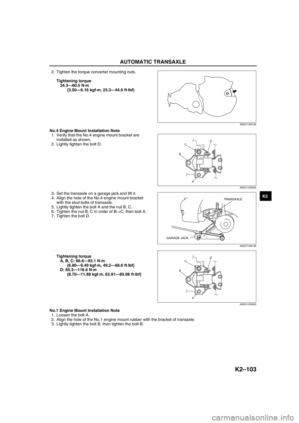
2. Tighten the torque converter mounting nuts.
Tightening torque
34.3—60.5 N·m
{3.50—6.16 kgf·m, 25.3—44.6 ft·lbf}
No.4 Engine Mount Installation Note
1. Verify that the No.4 engine mount bracket are
installed as shown.
2. Lightly tighten the bolt D.
3. Set the transaxle on a garage jack and lift it.
4. Align the hole of the No.4 engine mount bracket
with the stud bolts of transaxle.
5. Lightly tighten the bolt A and the nut B, C.
6. Tighten the nut B, C in order of B→C, then bolt A.
7. Tighten the bolt D.
8.
Tightening torque
A, B, C: 66.6—93.1 N·m
{6.80—9.49 kgf·m, 49.2—68.6 ft·lbf}
D: 85.3—116.6 N·m
{8.70—11.88 kgf·m, 62.91—85.98 ft·lbf}
No.1 Engine Mount Installation Note
1. Loosen the bolt A.
2. Align the hole of the No.1 engine mount rubber with the bracket of transaxle.
3. Lightly tighten the bolt B, then tighten the bolt B.
A6E5714W136
D
A BC
A6E5112W005
TRANSAXLE
GARAGE JACK
A6E5714W139
D
A BC
A6E5112W005
Page 520 of 909
AUTOMATIC TRANSAXLE
K2–105
K2
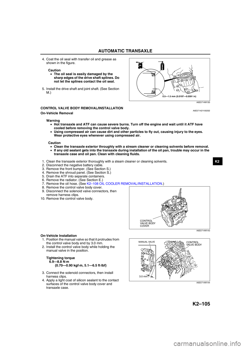
4. Coat the oil seal with transfer oil and grease as
shown in the figure.
Caution
•The oil seal is easily damaged by the
sharp edges of the drive shaft splines. Do
not let the splines contact the oil seal.
5. Install the drive shaft and joint shaft. (See Section
M.)
End Of SieCONTROL VALVE BODY REMOVAL/INSTALLATIONA6E571421100202On-Vehicle Removal
Warning
•Hot transaxle and ATF can cause severe burns. Turn off the engine and wait until it ATF have
cooled before removing the control valve body.
•Using compressed air can cause dirt and other particles to fly out, causing injury to the eyes.
Wear protective eyes whenever using compressed air.
Caution
•Clean the transaxle exterior throughly with a stream cleaner or cleaning solvents before removal.
•If any old sealant gets into the transaxle during installation of the oil pan, trouble may occur in the
transaxle case and oil pan. Clean with cleaning fluids.
1. Clean the transaxle exterior thoroughly with a steam cleaner or cleaning solvents.
2. Disconnect the negative battery cable.
3. Remove the front bumper. (See Section S.)
4. Remove the shroud panel. (See Section S.)
5. Drain the ATF into separate containers.
6. Remove the radiator. (See Section E.)
7. Remove the oil hose. (See K2–108 OIL COOLER REMOVAL/INSTALLATION.)
8. Remove the control valve body cover.
9. Disconnect the solenoid valve connectors, then
remove harness clips.
10. Remove the control valve body.
On-Vehicle Installation
1. Position the manual valve so that it protrudes from
the control valve body end by 3.0 mm.
2. Install the control valve body while holding the
manual valve in the position.
Tightening torque
6.9—8.8 N·m
{0.70—0.90 kgf·m, 5.1—6.5 ft·lbf}
3. Connect the solenoid connectors, then install
harness clips.
4. Apply a light coat of silicon sealant to the contact
surfaces of the control valve body cover and
transaxle case.
OILOIL
0.5—1.5 mm {0.0197—0.0591 in}
GREASEGREASE
A6E5714W130
CONTROL
VALVE BODY
COVER
A6E5714W143
3.0 mm
MANUAL VALVECONTROL
VALVE BODY
A6E5714W144
Page 527 of 909
K2–112
AUTOMATIC TRANSAXLE
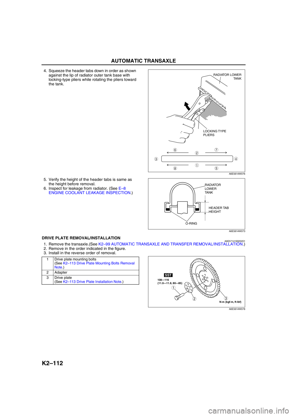
4. Squeeze the header tabs down in order as shown
against the lip of radiator outer tank base with
locking-type pliers while rotating the pliers toward
the tank.
5. Verify the height of the header tabs is same as
the height before removal.
6. Inspect for leakage from radiator. (See E–8
ENGINE COOLANT LEAKAGE INSPECTION.)
End Of SieDRIVE PLATE REMOVAL/INSTALLATIONA6E5714190202011. Remove the transaxle.(See K2–99 AUTOMATIC TRANSAXLE AND TRANSFER REMOVAL/INSTALLATION.)
2. Remove in the order indicated in the figure.
3. Install in the reverse order of removal.
.
8
7
5
43
6
1
2
LOCKING TYPE
PLIERSRADIATOR LOWER
TANK
A6E5614W076
RADIATOR
LOWER
TANK
HEADER TAB
HEIGHT
O-RING
A6E5614W073
1 Drive plate mounting bolts
(See K2–113 Drive Plate Mounting Bolts Removal
Note.)
2 Adapter
3 Drive plate
(See K2–113 Drive Plate Installation Note.)
N·m {kgf·m, ft·lbf} 108—116
{11.0—11.8, 80—85}
SST
3
1
2
A6E5614W078
Page 530 of 909
TRANSFER
K2–115
K2
End Of SieTRANSFER REMOVAL/INSTALLATIONA6E5718170012041. Disconnect the negative battery cable.
2. Remove the propeller shaft. (See L–5 PROPELLER SHAFT REMOVAL/INSTALLATION.)
3. Remove the TWC. (See F1–30 EXHAUST SYSTEM REMOVAL/INSTALLATION.)
4. Remove the front tires and splash shield of right side.
5. Remove the under cover.
6. Remove the drive shaft of right side. (See Section M.)
7. Remove the joint shaft. (See Section M.)
8. Remove the exhaust manifold insulator. (See F1–30 EXHAUST SYSTEM REMOVAL/INSTALLATION.)
9. Remove the exhaust manifold. (See F1–30 EXHAUST SYSTEM REMOVAL/INSTALLATION.)
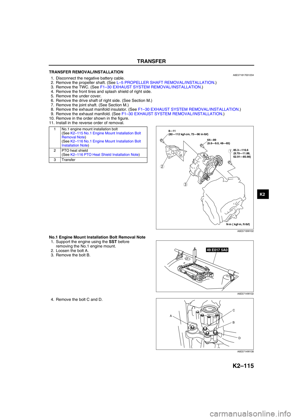
10. Remove in the order shown in the figure.
11. Install in the reverse order of removal.
.
No.1 Engine Mount Installation Bolt Removal Note
1. Support the engine using the SST before
removing the No.1 engine mount.
2. Loosen the bolt A.
3. Remove the bolt B.
4. Remove the bolt C and D.
1 No.1 engine mount installation bolt
(See K2–115 No.1 Engine Mount Installation Bolt
Removal Note)
(See K2–116 No.1 Engine Mount Installation Bolt
Installation Note)
2 PTO heat shield
(See K2–116 PTO Heat Shield Installation Note)
3Transfer
2
3
N·m { kgf·m, ft·lbf} 8—11
{82—112 kgf·cm, 72—96 in·lbf}
64—89
{6.6—9.0, 48—65}
185.3—116.6
{8.70—11.88,
62.91—85.98}
A6E5718W102
49 E017 5A0
A6E5714W132
AC
B
D
A6E5714W138
Page 531 of 909
K2–116
TRANSFER
No.1 Engine Mount Installation Bolt Installation Note
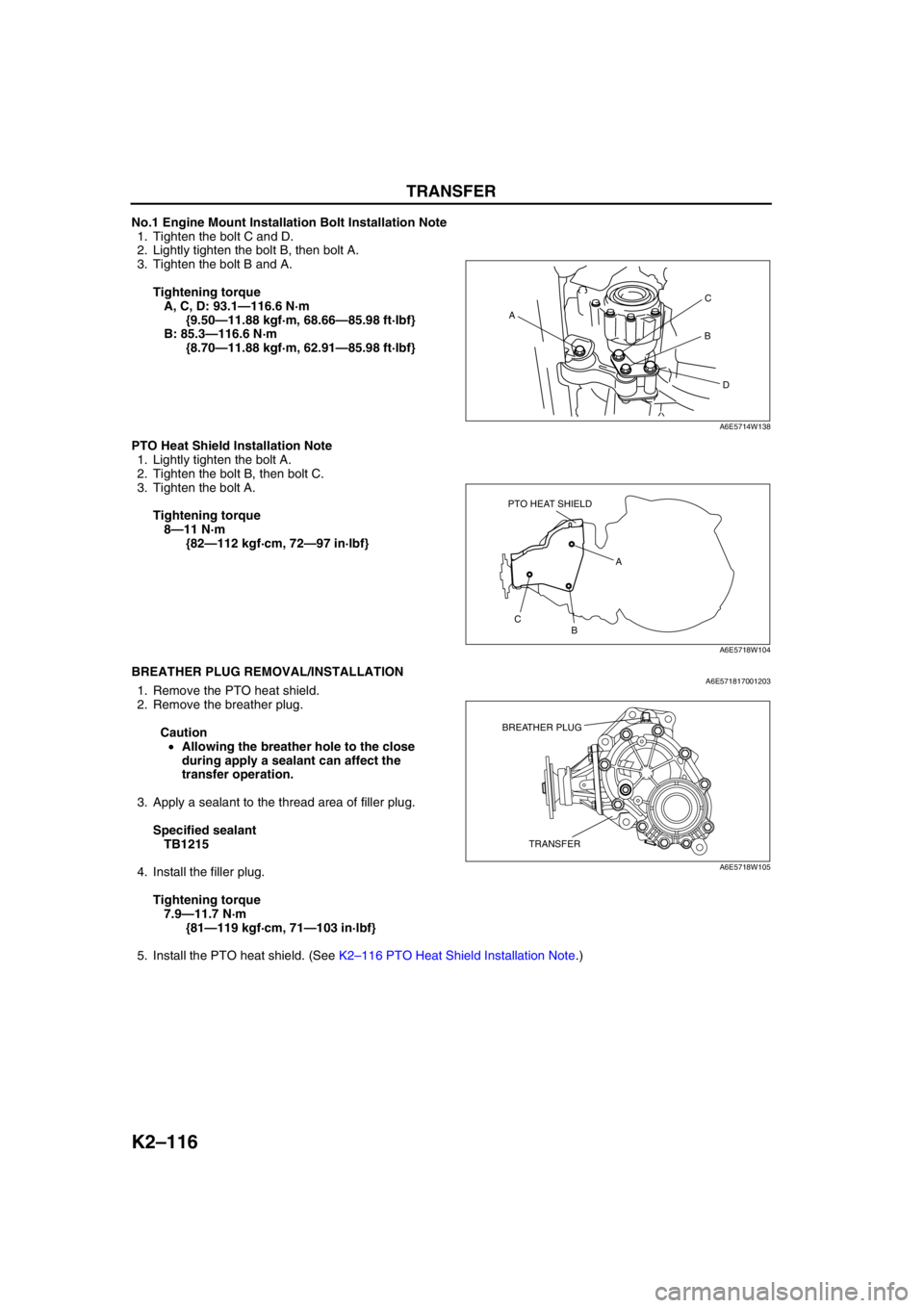
1. Tighten the bolt C and D.
2. Lightly tighten the bolt B, then bolt A.
3. Tighten the bolt B and A.
Tightening torque
A, C, D: 93.1—116.6 N·m
{9.50—11.88 kgf·m, 68.66—85.98 ft·lbf}
B: 85.3—116.6 N·m
{8.70—11.88 kgf·m, 62.91—85.98 ft·lbf}
PTO Heat Shield Installation Note
1. Lightly tighten the bolt A.
2. Tighten the bolt B, then bolt C.
3. Tighten the bolt A.
Tightening torque
8—11 N·m
{82—112 kgf·cm, 72—97 in·lbf}
End Of SieBREATHER PLUG REMOVAL/INSTALLATIONA6E5718170012031. Remove the PTO heat shield.
2. Remove the breather plug.
Caution
•Allowing the breather hole to the close
during apply a sealant can affect the
transfer operation.
3. Apply a sealant to the thread area of filler plug.
Specified sealant
TB1215
4. Install the filler plug.
Tightening torque
7.9—11.7 N·m
{81—119 kgf·cm, 71—103 in·lbf}
5. Install the PTO heat shield. (See K2–116 PTO Heat Shield Installation Note.)
End Of Sie
AC
B
D
A6E5714W138
PTO HEAT SHIELD
A
B C
A6E5718W104
TRANSFER BREATHER PLUG
A6E5718W105
Page 532 of 909
AUTOMATIC TRANSAXLE SHIFT MECHANISM
K2–117
K2
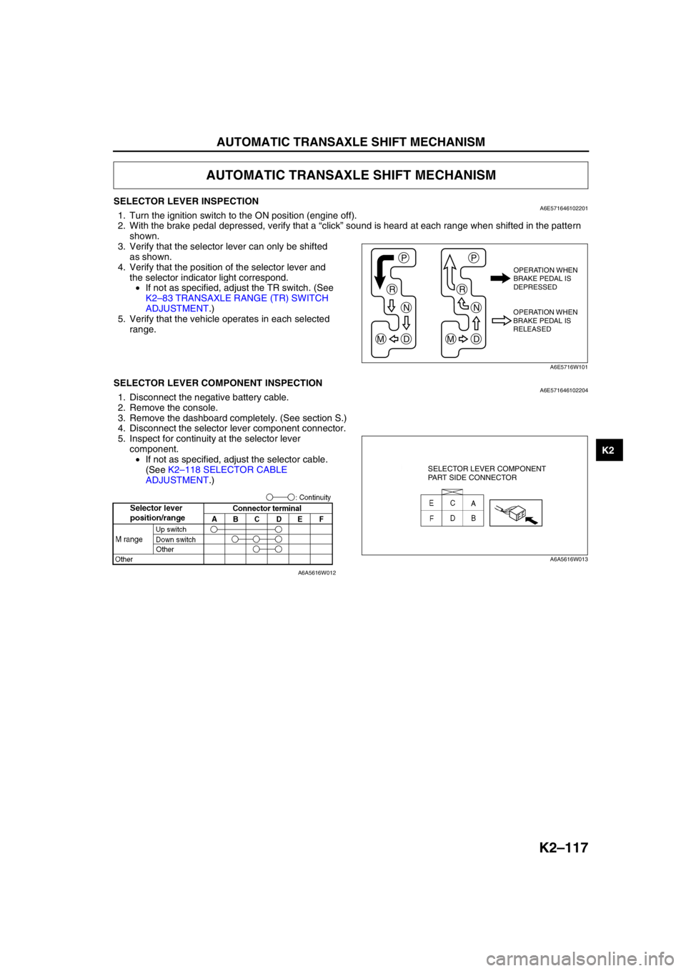
SELECTOR LEVER INSPECTIONA6E5716461022011. Turn the ignition switch to the ON position (engine off).
2. With the brake pedal depressed, verify that a “click” sound is heard at each range when shifted in the pattern
shown.
3. Verify that the selector lever can only be shifted
as shown.
4. Verify that the position of the selector lever and
the selector indicator light correspond.
•If not as specified, adjust the TR switch. (See
K2–83 TRANSAXLE RANGE (TR) SWITCH
ADJUSTMENT.)
5. Verify that the vehicle operates in each selected
range.
End Of SieSELECTOR LEVER COMPONENT INSPECTIONA6E5716461022041. Disconnect the negative battery cable.
2. Remove the console.
3. Remove the dashboard completely. (See section S.)
4. Disconnect the selector lever component connector.
5. Inspect for continuity at the selector lever
component.
•If not as specified, adjust the selector cable.
(See K2–118 SELECTOR CABLE
ADJUSTMENT.)
End Of Sie
AUTOMATIC TRANSAXLE SHIFT MECHANISM
P
R
N
DM
P
R
N
DM
OPERATION WHEN
BRAKE PEDAL IS
DEPRESSED
OPERATION WHEN
BRAKE PEDAL IS
RELEASED
A6E5716W101
SELECTOR LEVER COMPONENT
PART SIDE CONNECTOR
A6A5616W013
A6A5616W012