4WD MAZDA 6 2002 Suplement Owner's Guide
[x] Cancel search | Manufacturer: MAZDA, Model Year: 2002, Model line: 6, Model: MAZDA 6 2002Pages: 909, PDF Size: 17.16 MB
Page 418 of 909
OUTLINE
K2–3
K2
FEATURESA6E570201030201ATX
Improved marketability
•New JA5AX-EL automatic transaxle for 4WD is used with on L3 engine.
Improved shift quality
•Five speed automatic transaxle has been adopted.
•The feedback control system has been adopted.
•The centrifugal balance clutch chambers have been adopted.
•A plate-type clutch pack replaces the band brake in the 2-4 brake.
High efficiency, compactness, and light weight
•Miniature trochoid gear type oil pump with torque converter direct drive has been adopted.
End Of Sie
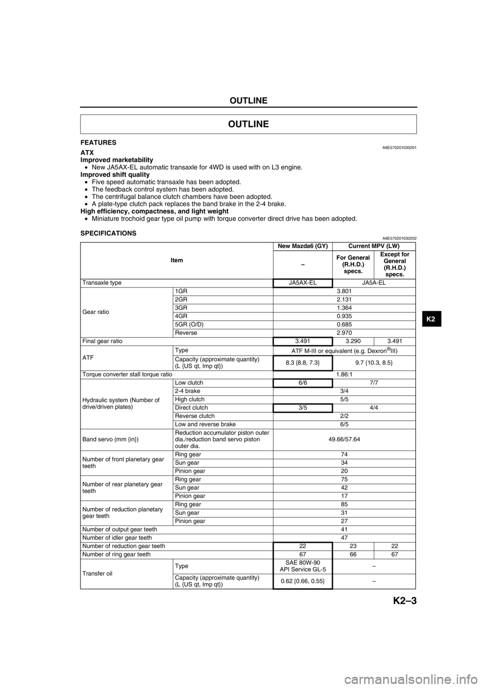
SPECIFICATIONSA6E570201030202
OUTLINE
ItemNew Mazda6 (GY) Current MPV (LW)
–For General
(R.H.D.)
specs.Except for
General
(R.H.D.)
specs.
Transaxle type JA5AX-EL JA5A-EL
Gear ratio1GR 3.801
2GR 2.131
3GR 1.364
4GR 0.935
5GR (O/D) 0.685
Reverse 2.970
Final gear ratio 3.491 3.290 3.491
ATFType
ATF M-III or equivalent (e.g. Dexron
®III)
Capacity (approximate quantity)
(L {US qt, Imp qt})8.3 {8.8, 7.3} 9.7 {10.3, 8.5}
Torque converter stall torque ratio 1.86:1
Hydraulic system (Number of
drive/driven plates)Low clutch 6/6 7/7
2-4 brake 3/4
High clutch 5/5
Direct clutch 3/5 4/4
Reverse clutch 2/2
Low and reverse brake 6/5
Band servo (mm {in})Reduction accumulator piston outer
dia./reduction band servo piston
outer dia.49.66/57.64
Number of front planetary gear
teethRing gear 74
Sun gear 34
Pinion gear 20
Number of rear planetary gear
teethRing gear 75
Sun gear 42
Pinion gear 17
Number of reduction planetary
gear teethRing gear 85
Sun gear 31
Pinion gear 27
Number of output gear teeth 41
Number of idler gear teeth 47
Number of reduction gear teeth 22 23 22
Number of ring gear teeth 67 66 67
Transfer oilTypeSAE 80W-90
API Service GL-5–
Capacity (approximate quantity)
(L {US qt, Imp qt})0.62 {0.66, 0.55}–
Page 487 of 909
K2–72
AUTOMATIC TRANSAXLE
MECHANICAL SYSTEM TESTA6E571401030209Mechanical System Test Preparation
1. Apply the parking brake and use wheel chocks at the front and rear of the wheels.
2. Inspect the engine coolant. (See Section E.)
3. Inspect the engine oil. (See D–8 ENGINE OIL INSPECTION.)
4. Inspect the ATF levels. (See K2–79 Automatic Transaxle Fluid (ATF) Level Inspection.)
5. Inspect the idle speed and ignition timing in P position. (See F1–22 IDLE SPEED INSPECTION (4WD).)
Line Pressure Test
Note
•Line pressure cannot be measured on the JA5AX-EL automatic transaxle. Measure the low clutch
pressure in place of D and M range line pressures. Measure the reverse clutch pressure in place of R
position line pressure.
1. Engine idling.
(1) Perform mechanical system test preparation. (See K2–72 Mechanical System Test Preparation.)
Warning
•Removing the plug when the ATF is hot can be dangerous. Hot ATF can come out of the opening
and badly burn you. Before removing the square-head plug, allow the ATF to cool.
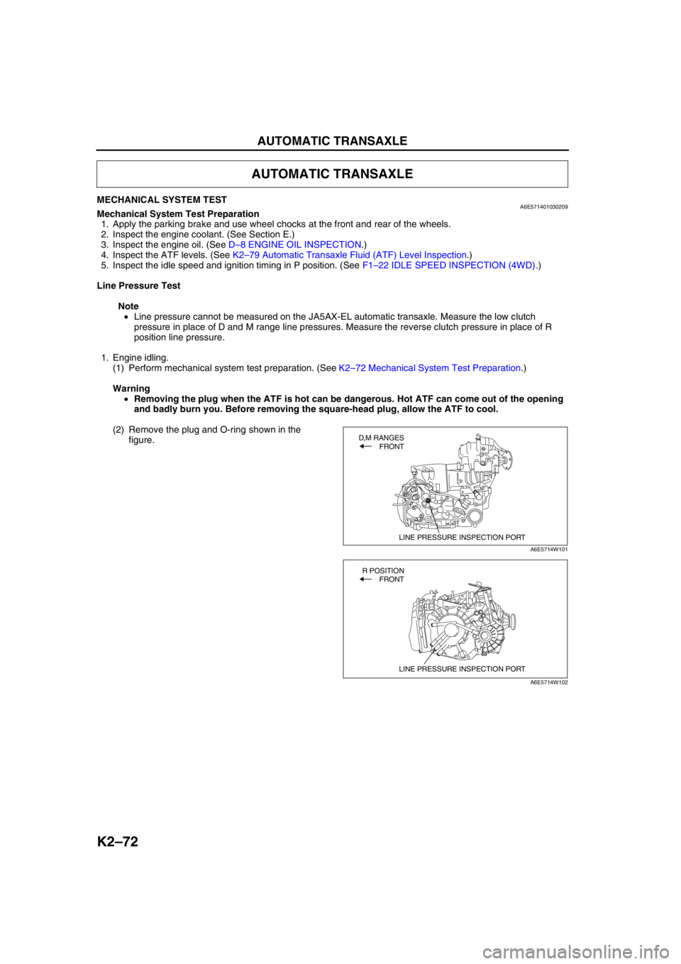
(2) Remove the plug and O-ring shown in the
figure.
AUTOMATIC TRANSAXLE
LINE PRESSURE INSPECTION PORT
D,M RANGES
FRONT
A6E5714W101
LINE PRESSURE INSPECTION PORT
R POSITION
FRONT
A6E5714W102
Page 490 of 909
AUTOMATIC TRANSAXLE
K2–75
K2
Time Lag Test
1. Perform mechanical system test preparation. (See K2–72 Mechanical System Test Preparation.)
2. Start the engine.
3. Warm up the engine until the ATF temperature reaches 60—70°C {140—158°F}. Shift the selector lever from N
position to D range.
4. Use a stopwatch to measure the time it takes from shifting until engagement is felt. Take three measurements
for each test and average the results using the following formula.
Formula
Average time lag = (Time 1 + Time 2 + Time 3) / 3
5. Perform the test for the following shifts in the same manner.
•N position → P position
Time lag
N → D range ... approx. 0.5—1.0 second
N → R position ... approx. 0.6— 1.0 second
Evaluation of time lag test
End Of SieROAD TESTA6E571401030210Road Test Preparation
1. Inspect the engine coolant. (See Section E.)
2. Inspect the engine oil. (See D–8 ENGINE OIL INSPECTION.)
3. Inspect the ATF levels. (See K2–78 AUTOMATIC TRANSAXLE FLUID (ATF) INSPECTION.)
4. Inspect the idle speed and ignition timing in P position. (See F1–22 IDLE SPEED INSPECTION (4WD).)
5. Bring up the engine and transaxle to normal operating temperature.
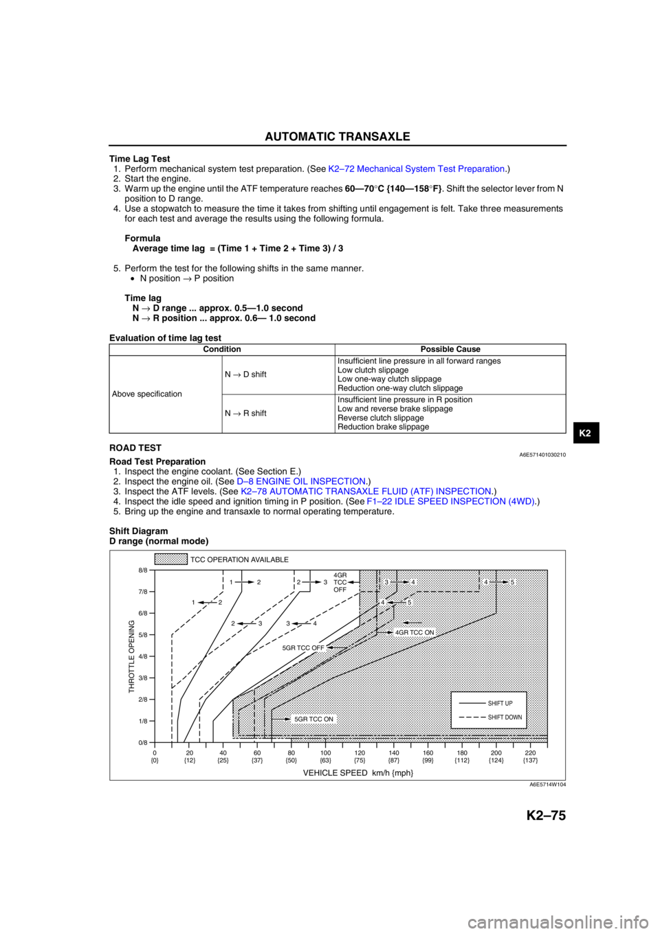
Shift Diagram
D range (normal mode)
Condition Possible Cause
Above specificationN → D shiftInsufficient line pressure in all forward ranges
Low clutch slippage
Low one-way clutch slippage
Reduction one-way clutch slippage
N → R shiftInsufficient line pressure in R position
Low and reverse brake slippage
Reverse clutch slippage
Reduction brake slippage
0/8 1/8
2/8
3/8
4/8
5/8
6/8
7/8
8/8
TCC OPERATION AVAILABLE
VEHICLE SPEED km/h {mph}
THROTTLE OPENING
SHIFT UP
4GR
TCC
OFF
SHIFT DOWN
0
{0}20
{12}40
{25}60
{37}80
{50}100
{63}120
{75}140
{87}160
{99}180
{112}220
{137} 200
{124} 112 23
2
2 232
34
4534
45
5GR TCC ON
4GR TCC ON
5GR TCC OFF
A6E5714W104
Page 512 of 909
AUTOMATIC TRANSAXLE
K2–97
K2
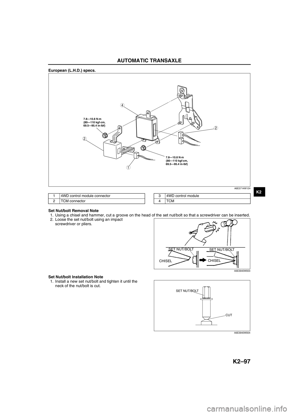
European (L.H.D.) specs.
.
Set Nut/bolt Removal Note
1. Using a chisel and hammer, cut a groove on the head of the set nut/bolt so that a screwdriver can be inserted.
2. Loose the set nut/bolt using an impact
screwdriver or pliers.
Set Nut/bolt Installation Note
1. Install a new set nut/bolt and tighten it until the
neck of the nut/bolt is cut.
2
4
7.8—10.8 N·m
{80—110 kgf·cm,
69.5—95.4 in·lbf} 7.8—10.8 N·m
{80—110 kgf·cm,
69.5—95.4 in·lbf}
2
1
A6E5714W124
1 4WD control module connector
2 TCM connector3 4WD control module
4TCM
CHISELCHISEL SET NUT/BOLT
SET NUT/BOLT
A6E3940W003
SET NUT/BOLT
CUT
A6E3940W004
Page 514 of 909
AUTOMATIC TRANSAXLE
K2–99
K2
AUTOMATIC TRANSAXLE AND TRANSFER REMOVAL/INSTALLATIONA6E5714190902011. Disconnect the negative battery cable.
2. Remove the battery and battery tray.
3. Remove the aircleaner component. (See Sectin F.)
4. Remove the front tires and splash shield.
5. Remove the under cover.
6. Separate the steering shaft and steering hose. (See N–13 STEERING GEAR AND LINKAGE (4WD)
REMOVAL/INSTALLATION.)
7. Remove the front auto leveling sensor. (See Section T.)
8. Drain the ATF. (See K2–80 AUTOMATIC TRANSAXLE FLUID (ATF) REPLACEMENT.)
Warning
•Improperly jacking a transaxle is dangerous. It can slip off the jack and may cause serious injury.
Caution
•To prevent the torque converter and transaxle from separating, remove the transaxle without
tilting it toward the torque converter.
9. Remove in the order shown in the figure.
10. Install in the reverse order of removal.
11. Adjust the headlight zeroset. (See Section T.)
12. Add ATF to the specified level. (See K2–80 AUTOMATIC TRANSAXLE FLUID (ATF) REPLACEMENT.)
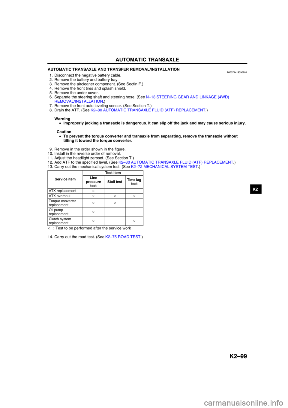
13. Carry out the mechanical system test. (See K2–72 MECHANICAL SYSTEM TEST.)
×: Test to be performed after the service work
14. Carry out the road test. (See K2–75 ROAD TEST.)
Service itemTest item
Line
pressure
testStall testTime lag
test
ATX replacement×
ATX overhaul×××
Torque converter
replacement××
Oil pump
replacement×
Clutch system
replacement××
Page 516 of 909
AUTOMATIC TRANSAXLE
K2–101
K2
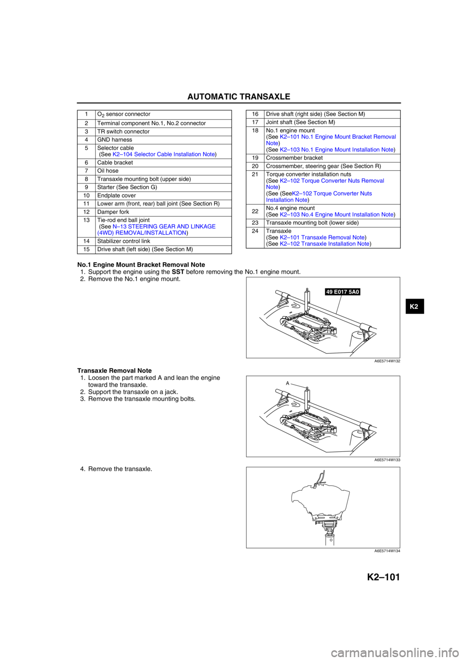
No.1 Engine Mount Bracket Removal Note
1. Support the engine using the SST before removing the No.1 engine mount.
2. Remove the No.1 engine mount.
Transaxle Removal Note
1. Loosen the part marked A and lean the engine
toward the transaxle.
2. Support the transaxle on a jack.
3. Remove the transaxle mounting bolts.
4. Remove the transaxle.
1O2 sensor connector
2 Terminal component No.1, No.2 connector
3 TR switch connector
4 GND harness
5 Selector cable
(See K2–104 Selector Cable Installation Note)
6 Cable bracket
7 Oil hose
8 Transaxle mounting bolt (upper side)
9 Starter (See Section G)
10 Endplate cover
11 Lower arm (front, rear) ball joint (See Section R)
12 Damper fork
13 Tie-rod end ball joint
(See N–13 STEERING GEAR AND LINKAGE
(4WD) REMOVAL/INSTALLATION)
14 Stabilizer control link
15 Drive shaft (left side) (See Section M)16 Drive shaft (right side) (See Section M)
17 Joint shaft (See Section M)
18 No.1 engine mount
(See K2–101 No.1 Engine Mount Bracket Removal
Note)
(See K2–103 No.1 Engine Mount Installation Note)
19 Crossmember bracket
20 Crossmember, steering gear (See Section R)
21 Torque converter installation nuts
(See K2–102 Torque Converter Nuts Removal
Note)
(See (SeeK2–102 Torque Converter Nuts
Installation Note)
22No.4 engine mount
(See K2–103 No.4 Engine Mount Installation Note)
23 Transaxle mounting bolt (lower side)
24 Transaxle
(See K2–101 Transaxle Removal Note)
(See K2–102 Transaxle Installation Note)
49 E017 5A0
A6E5714W132
A
A6E5714W133
A6E5714W134
Page 618 of 909
L–2
OUTLINE
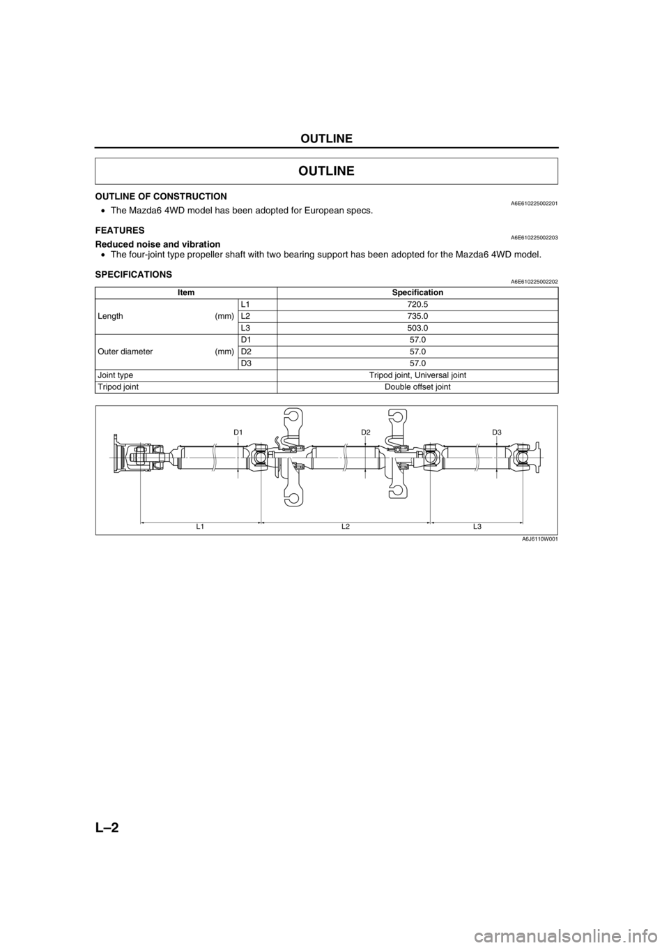
OUTLINE OF CONSTRUCTIONA6E610225002201•The Mazda6 4WD model has been adopted for European specs.
End Of Sie
FEATURESA6E610225002203Reduced noise and vibration
•The four-joint type propeller shaft with two bearing support has been adopted for the Mazda6 4WD model.
End Of Sie
SPECIFICATIONSA6E610225002202
End Of Sie
OUTLINE
Item Specification
Length (mm)L1 720.5
L2 735.0
L3 503.0
Outer diameter (mm)D1 57.0
D2 57.0
D3 57.0
Joint type Tripod joint, Universal joint
Tripod joint Double offset joint
D3 D2 D1
L3 L2 L1
A6J6110W001
Page 631 of 909
M–1
M
MFRONT AND REAR AXLES
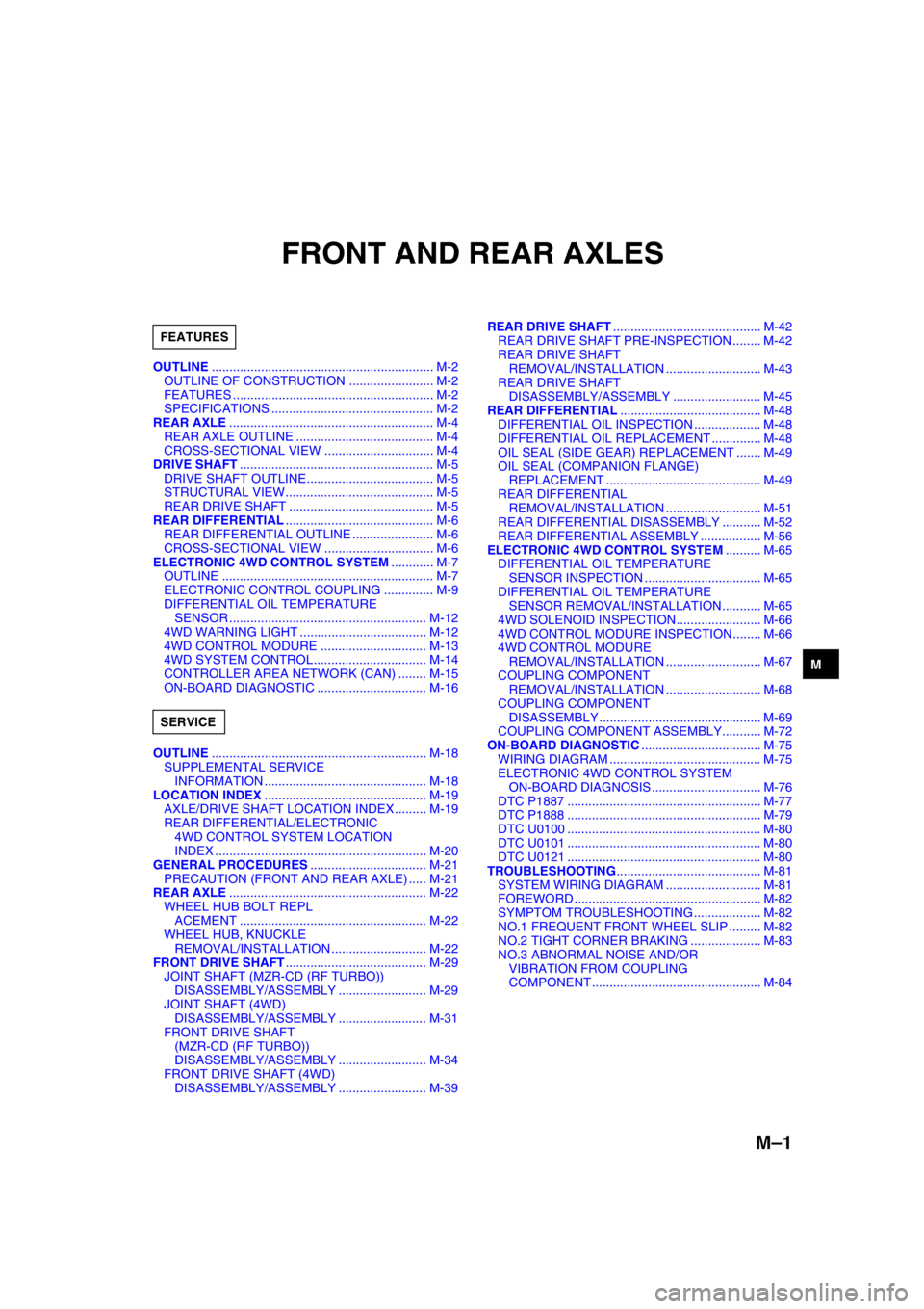
OUTLINE............................................................... M-2
OUTLINE OF CONSTRUCTION ........................ M-2
FEATURES ......................................................... M-2
SPECIFICATIONS .............................................. M-2
REAR AXLE.......................................................... M-4
REAR AXLE OUTLINE ....................................... M-4
CROSS-SECTIONAL VIEW ............................... M-4
DRIVE SHAFT....................................................... M-5
DRIVE SHAFT OUTLINE.................................... M-5
STRUCTURAL VIEW.......................................... M-5
REAR DRIVE SHAFT ......................................... M-5
REAR DIFFERENTIAL.......................................... M-6
REAR DIFFERENTIAL OUTLINE ....................... M-6
CROSS-SECTIONAL VIEW ............................... M-6
ELECTRONIC 4WD CONTROL SYSTEM............ M-7
OUTLINE ............................................................ M-7
ELECTRONIC CONTROL COUPLING .............. M-9
DIFFERENTIAL OIL TEMPERATURE
SENSOR ........................................................ M-12
4WD WARNING LIGHT .................................... M-12
4WD CONTROL MODURE .............................. M-13
4WD SYSTEM CONTROL................................ M-14
CONTROLLER AREA NETWORK (CAN) ........ M-15
ON-BOARD DIAGNOSTIC ............................... M-16
OUTLINE............................................................. M-18
SUPPLEMENTAL SERVICE
INFORMATION .............................................. M-18
LOCATION INDEX.............................................. M-19
AXLE/DRIVE SHAFT LOCATION INDEX ......... M-19
REAR DIFFERENTIAL/ELECTRONIC
4WD CONTROL SYSTEM LOCATION
INDEX ............................................................ M-20
GENERAL PROCEDURES................................. M-21
PRECAUTION (FRONT AND REAR AXLE) ..... M-21
REAR AXLE........................................................ M-22
WHEEL HUB BOLT REPL
ACEMENT ..................................................... M-22
WHEEL HUB, KNUCKLE
REMOVAL/INSTALLATION ........................... M-22
FRONT DRIVE SHAFT........................................ M-29
JOINT SHAFT (MZR-CD (RF TURBO))
DISASSEMBLY/ASSEMBLY ......................... M-29
JOINT SHAFT (4WD)
DISASSEMBLY/ASSEMBLY ......................... M-31
FRONT DRIVE SHAFT
(MZR-CD (RF TURBO))
DISASSEMBLY/ASSEMBLY ......................... M-34
FRONT DRIVE SHAFT (4WD)
DISASSEMBLY/ASSEMBLY ......................... M-39REAR DRIVE SHAFT.......................................... M-42
REAR DRIVE SHAFT PRE-INSPECTION ........ M-42
REAR DRIVE SHAFT
REMOVAL/INSTALLATION ........................... M-43
REAR DRIVE SHAFT
DISASSEMBLY/ASSEMBLY ......................... M-45
REAR DIFFERENTIAL........................................ M-48
DIFFERENTIAL OIL INSPECTION ................... M-48
DIFFERENTIAL OIL REPLACEMENT .............. M-48
OIL SEAL (SIDE GEAR) REPLACEMENT ....... M-49
OIL SEAL (COMPANION FLANGE)
REPLACEMENT ............................................ M-49
REAR DIFFERENTIAL
REMOVAL/INSTALLATION ........................... M-51
REAR DIFFERENTIAL DISASSEMBLY ........... M-52
REAR DIFFERENTIAL ASSEMBLY ................. M-56
ELECTRONIC 4WD CONTROL SYSTEM.......... M-65
DIFFERENTIAL OIL TEMPERATURE
SENSOR INSPECTION ................................. M-65
DIFFERENTIAL OIL TEMPERATURE
SENSOR REMOVAL/INSTALLATION ........... M-65
4WD SOLENOID INSPECTION........................ M-66
4WD CONTROL MODURE INSPECTION ........ M-66
4WD CONTROL MODURE
REMOVAL/INSTALLATION ........................... M-67
COUPLING COMPONENT
REMOVAL/INSTALLATION ........................... M-68
COUPLING COMPONENT
DISASSEMBLY .............................................. M-69
COUPLING COMPONENT ASSEMBLY........... M-72
ON-BOARD DIAGNOSTIC.................................. M-75
WIRING DIAGRAM ........................................... M-75
ELECTRONIC 4WD CONTROL SYSTEM
ON-BOARD DIAGNOSIS ............................... M-76
DTC P1887 ....................................................... M-77
DTC P1888 ....................................................... M-79
DTC U0100 ....................................................... M-80
DTC U0101 ....................................................... M-80
DTC U0121 ....................................................... M-80
TROUBLESHOOTING......................................... M-81
SYSTEM WIRING DIAGRAM ........................... M-81
FOREWORD ..................................................... M-82
SYMPTOM TROUBLESHOOTING ................... M-82
NO.1 FREQUENT FRONT WHEEL SLIP ......... M-82
NO.2 TIGHT CORNER BRAKING .................... M-83
NO.3 ABNORMAL NOISE AND/OR
VIBRATION FROM COUPLING
COMPONENT ................................................ M-84 FEATURES
SERVICE
Page 632 of 909
M–2
OUTLINE
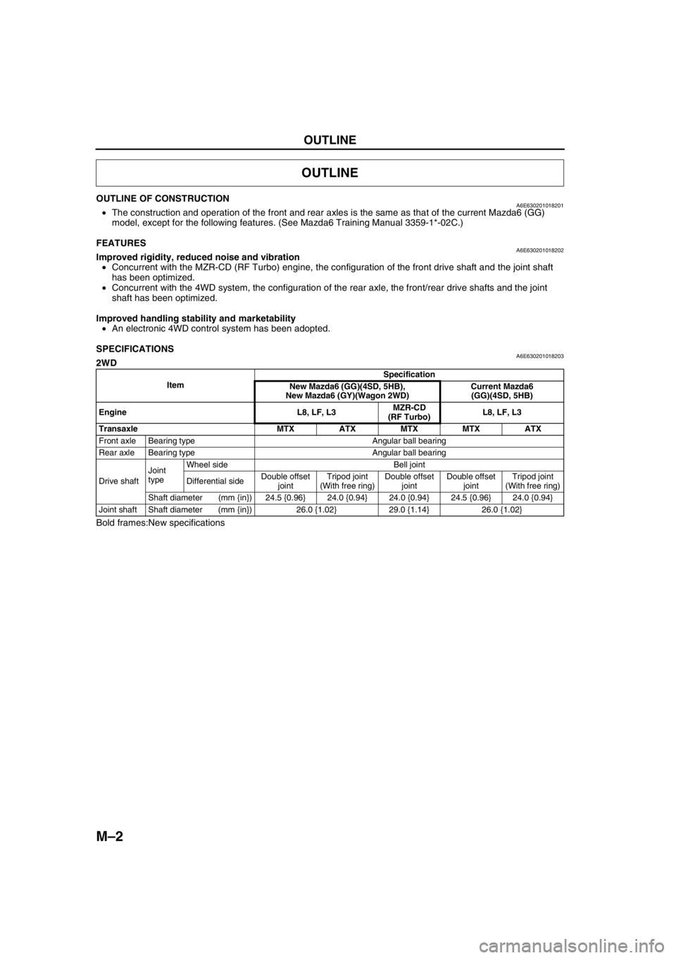
OUTLINE OF CONSTRUCTIONA6E630201018201•The construction and operation of the front and rear axles is the same as that of the current Mazda6 (GG)
model, except for the following features. (See Mazda6 Training Manual 3359-1*-02C.)
End Of Sie
FEATURESA6E630201018202Improved rigidity, reduced noise and vibration
•Concurrent with the MZR-CD (RF Turbo) engine, the configuration of the front drive shaft and the joint shaft
has been optimized.
•Concurrent with the 4WD system, the configuration of the rear axle, the front/rear drive shafts and the joint
shaft has been optimized.
Improved handling stability and marketability
•An electronic 4WD control system has been adopted.
End Of Sie
SPECIFICATIONSA6E6302010182032WD
Bold frames:New specifications
OUTLINE
ItemSpecification
New Mazda6 (GG)(4SD, 5HB),
New Mazda6 (GY)(Wagon 2WD)Current Mazda6
(GG)(4SD, 5HB)
Engine L8, LF, L3MZR-CD
(RF Turbo)L8, LF, L3
Transaxle MTX ATX MTX MTX ATX
Front axle Bearing type Angular ball bearing
Rear axle Bearing type Angular ball bearing
Drive shaftJoint
typeWheel side Bell joint
Differential sideDouble offset
jointTripod joint
(With free ring)Double offset
jointDouble offset
jointTripod joint
(With free ring)
Shaft diameter (mm {in}) 24.5 {0.96} 24.0 {0.94} 24.0 {0.94} 24.5 {0.96} 24.0 {0.94}
Joint shaft Shaft diameter (mm {in}) 26.0 {1.02} 29.0 {1.14} 26.0 {1.02}
Page 633 of 909
OUTLINE
M–3
M
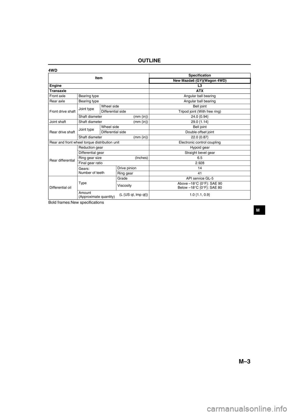
4WD
Bold frames:New specifications
End Of Sie
ItemSpecification
New Mazda6 (GY)(Wagon 4WD)
EngineL3
TransaxleATX
Front axle Bearing type Angular ball bearing
Rear axle Bearing type Angular ball bearing
Front drive shaftJoint typeWheel side Bell joint
Differential side Tripod joint (With free ring)
Shaft diameter (mm {in}) 24.0 {0.94}
Joint shaft Shaft diameter (mm {in}) 29.0 {1.14}
Rear drive shaftJoint typeWheel side Bell joint
Differential side Double offset joint
Shaft diameter (mm {in}) 22.0 {0.87}
Rear and front wheel torque distribution unit Electronic control coupling
Rear differentialReduction gear Hypoid gear
Differential gear Straight bevel gear
Ring gear size (Inches) 6.5
Final gear ratio 2.928
Gears:
Number of teethDrive pinion 14
Ring gear 41
Differential oilTypeGrade API service GL-5
ViscosityAbove –18°C {0°F}: SAE 90
Below –18°C {0°F}: SAE 80
Amount
(Approximate quantity)(L {US qt, lmp qt}) 1.0 {1.1, 0.9}