check engine MAZDA 6 2002 Suplement Service Manual
[x] Cancel search | Manufacturer: MAZDA, Model Year: 2002, Model line: 6, Model: MAZDA 6 2002Pages: 909, PDF Size: 17.16 MB
Page 303 of 909
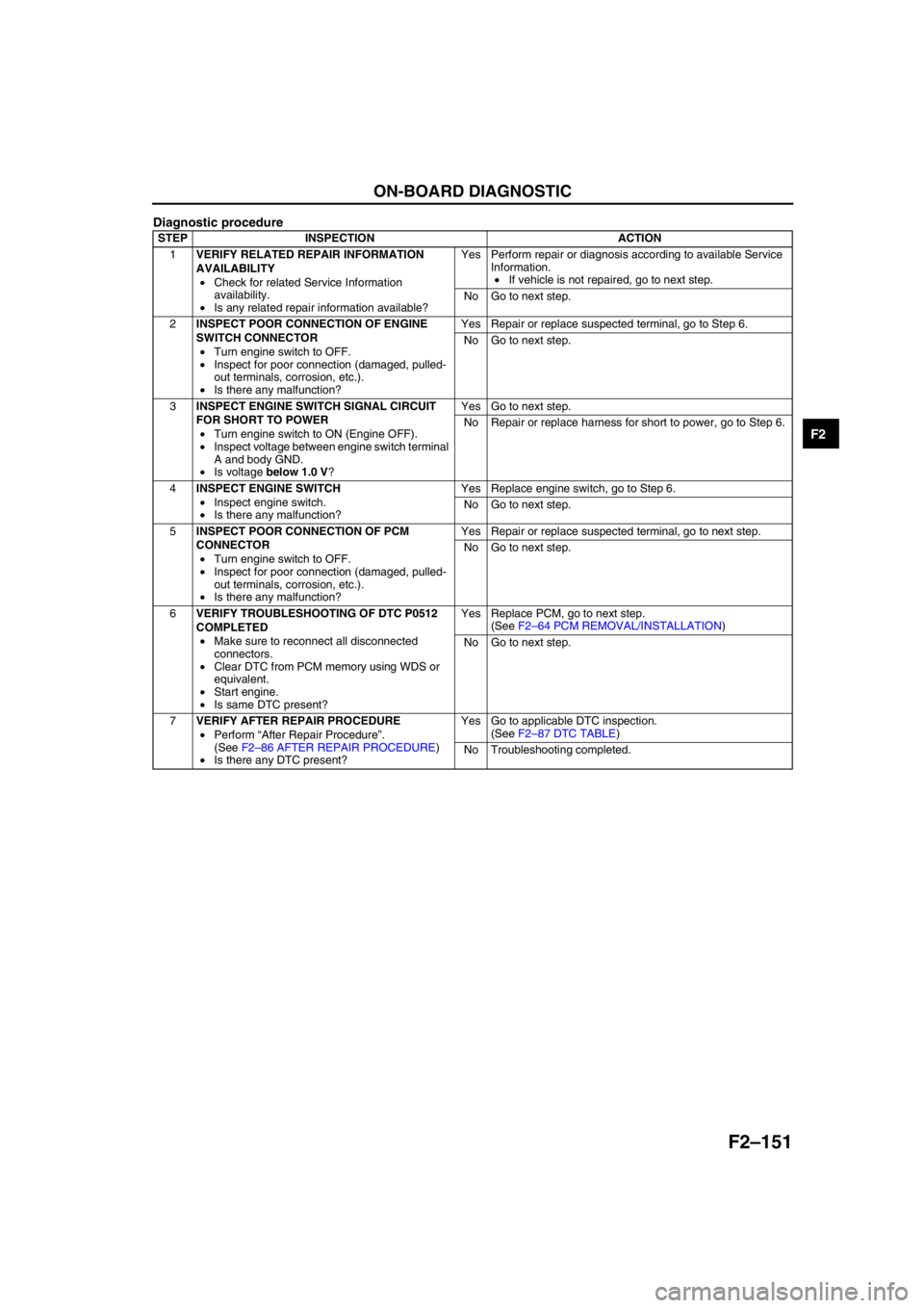
ON-BOARD DIAGNOSTIC
F2–151
F2
Diagnostic procedure
End Of Sie
STEP INSPECTION ACTION
1VERIFY RELATED REPAIR INFORMATION
AVAILABILITY
•Check for related Service Information
availability.
•Is any related repair information available?Yes Perform repair or diagnosis according to available Service
Information.
•If vehicle is not repaired, go to next step.
No Go to next step.
2INSPECT POOR CONNECTION OF ENGINE
SWITCH CONNECTOR
•Turn engine switch to OFF.
•Inspect for poor connection (damaged, pulled-
out terminals, corrosion, etc.).
•Is there any malfunction?Yes Repair or replace suspected terminal, go to Step 6.
No Go to next step.
3INSPECT ENGINE SWITCH SIGNAL CIRCUIT
FOR SHORT TO POWER
•Turn engine switch to ON (Engine OFF).
•Inspect voltage between engine switch terminal
A and body GND.
•Is voltage below 1.0 V?Yes Go to next step.
No Repair or replace harness for short to power, go to Step 6.
4INSPECT ENGINE SWITCH
•Inspect engine switch.
•Is there any malfunction?Yes Replace engine switch, go to Step 6.
No Go to next step.
5INSPECT POOR CONNECTION OF PCM
CONNECTOR
•Turn engine switch to OFF.
•Inspect for poor connection (damaged, pulled-
out terminals, corrosion, etc.).
•Is there any malfunction?Yes Repair or replace suspected terminal, go to next step.
No Go to next step.
6VERIFY TROUBLESHOOTING OF DTC P0512
COMPLETED
•Make sure to reconnect all disconnected
connectors.
•Clear DTC from PCM memory using WDS or
equivalent.
•Start engine.
•Is same DTC present?Yes Replace PCM, go to next step.
(See F2–64 PCM REMOVAL/INSTALLATION)
No Go to next step.
7VERIFY AFTER REPAIR PROCEDURE
•Perform “After Repair Procedure”.
(See F2–86 AFTER REPAIR PROCEDURE)
•Is there any DTC present?Yes Go to applicable DTC inspection.
(See F2–87 DTC TABLE)
No Troubleshooting completed.
Page 304 of 909
F2–152
ON-BOARD DIAGNOSTIC
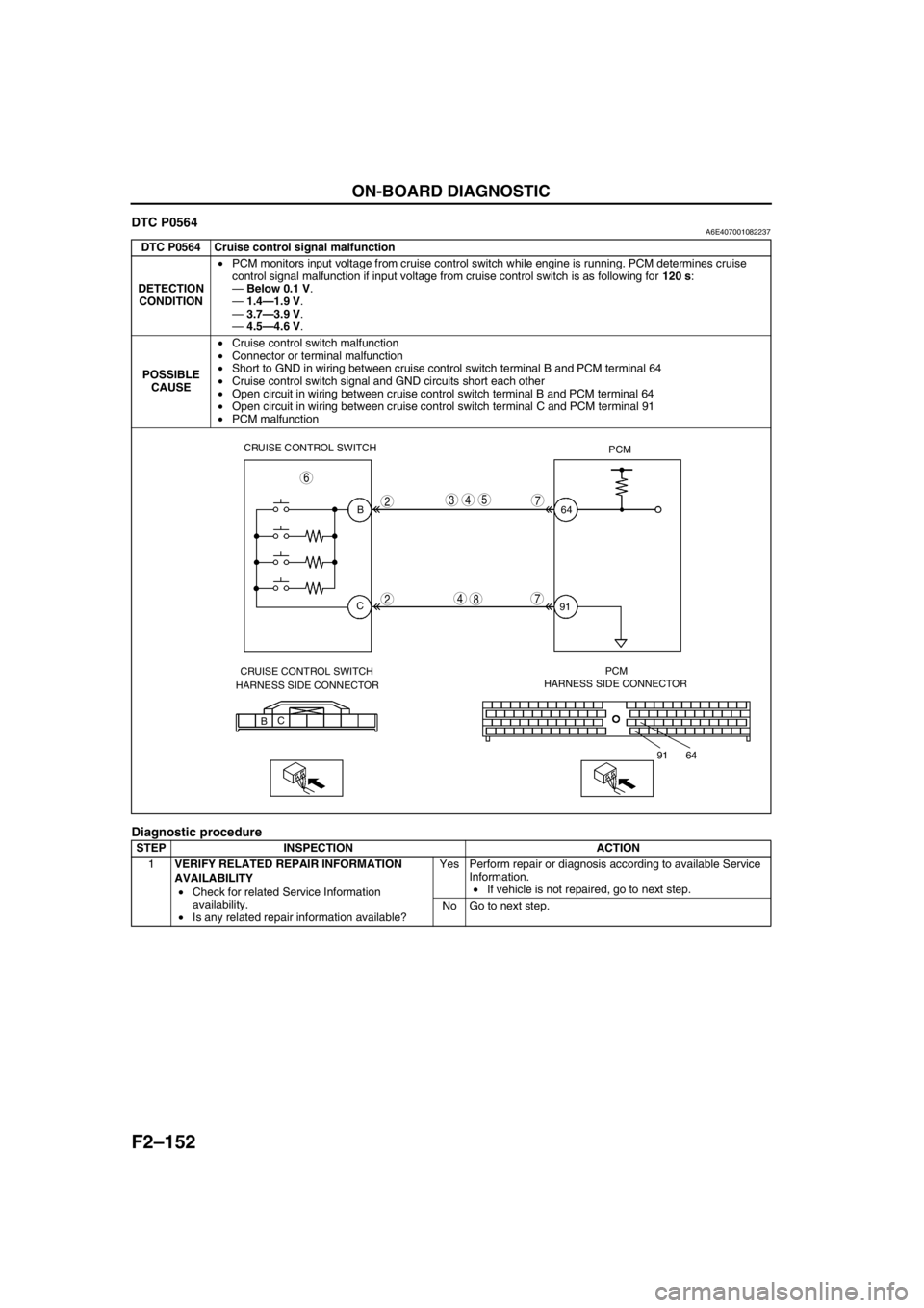
DTC P0564A6E407001082237
Diagnostic procedure
DTC P0564 Cruise control signal malfunction
DETECTION
CONDITION•PCM monitors input voltage from cruise control switch while engine is running. PCM determines cruise
control signal malfunction if input voltage from cruise control switch is as following for 120 s:
—Below 0.1 V.
—1.4—1.9 V.
—3.7—3.9 V.
—4.5—4.6 V.
POSSIBLE
CAUSE•Cruise control switch malfunction
•Connector or terminal malfunction
•Short to GND in wiring between cruise control switch terminal B and PCM terminal 64
•Cruise control switch signal and GND circuits short each other
•Open circuit in wiring between cruise control switch terminal B and PCM terminal 64
•Open circuit in wiring between cruise control switch terminal C and PCM terminal 91
•PCM malfunction
STEP INSPECTION ACTION
1VERIFY RELATED REPAIR INFORMATION
AVAILABILITY
•Check for related Service Information
availability.
•Is any related repair information available?Yes Perform repair or diagnosis according to available Service
Information.
•If vehicle is not repaired, go to next step.
No Go to next step.
CRUISE CONTROL SWITCH
PCM
B
C64
91
CRUISE CONTROL SWITCH
HARNESS SIDE CONNECTORPCM
HARNESS SIDE CONNECTOR
BC
64 91
2
2
543
4
7
6
78
Page 312 of 909
F2–160
ON-BOARD DIAGNOSTIC
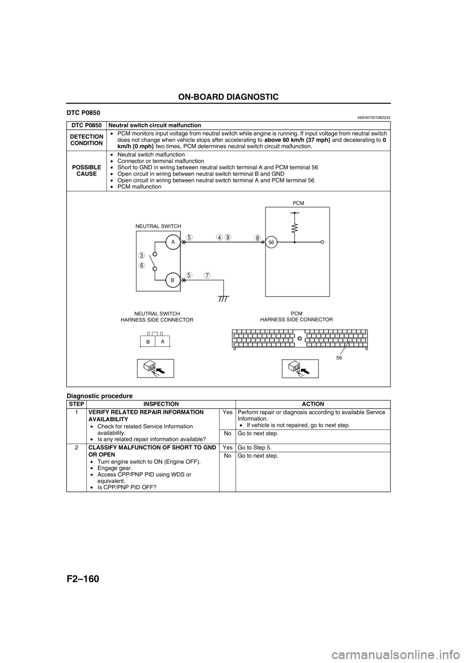
DTC P0850A6E407001082243
Diagnostic procedure
DTC P0850 Neutral switch circuit malfunction
DETECTION
CONDITION•PCM monitors input voltage from neutral switch while engine is running. If input voltage from neutral switch
does not change when vehicle stops after accelerating to above 60 km/h {37 mph} and decelerating to 0
km/h {0 mph} two times, PCM determines neutral switch circuit malfunction.
POSSIBLE
CAUSE•Neutral switch malfunction
•Connector or terminal malfunction
•Short to GND in wiring between neutral switch terminal A and PCM terminal 56
•Open circuit in wiring between neutral switch terminal B and GND
•Open circuit in wiring between neutral switch terminal A and PCM terminal 56
•PCM malfunction
STEP INSPECTION ACTION
1VERIFY RELATED REPAIR INFORMATION
AVAILABILITY
•Check for related Service Information
availability.
•Is any related repair information available?Yes Perform repair or diagnosis according to available Service
Information.
•If vehicle is not repaired, go to next step.
No Go to next step.
2CLASSIFY MALFUNCTION OF SHORT TO GND
OR OPEN
•Turn engine switch to ON (Engine OFF).
•Engage gear.
•Access CPP/PNP PID using WDS or
equivalent.
•Is CPP/PNP PID OFF?Yes Go to Step 5.
No Go to next step.
A
B
A
B NEUTRAL SWITCH
56PCM
56
3
6
5
5
7
498
NEUTRAL SWITCH
HARNESS SIDE CONNECTORPCM
HARNESS SIDE CONNECTOR
Page 314 of 909
F2–162
ON-BOARD DIAGNOSTIC
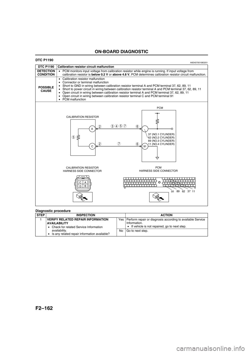
DTC P1190A6E407001083201
Diagnostic procedure
DTC P1190 Calibration resistor circuit malfunction
DETECTION
CONDITION•PCM monitors input voltage from calibration resistor while engine is running. If input voltage from
calibration resistor is below 0.2 V or above 4.8 V, PCM determines calibration resistor circuit malfunction.
POSSIBLE
CAUSE•Calibration resistor malfunction
•Connector or terminal malfunction
•Short to GND in wiring between calibration resistor terminal A and PCM terminal 37, 62, 89, 11
•Short to power circuit in wiring between calibration resistor terminal A and PCM terminal 37, 62, 89, 11
•Open circuit in wiring between calibration resistor terminal A and PCM terminal 37, 62, 89, 11
•Open circuit in wiring between calibration resistor terminal C and PCM terminal 91
•PCM malfunction
STEP INSPECTION ACTION
1VERIFY RELATED REPAIR INFORMATION
AVAILABILITY
•Check for related Service Information
availability.
•Is any related repair information available?Yes Perform repair or diagnosis according to available Service
Information.
•If vehicle is not repaired, go to next step.
No Go to next step.
A
C
C
A
DBPCM
HARNESS SIDE CONNECTOR91PCM
CALIBRATION RESISTOR
5
2
2
5437
7
6
6
11 37
62 89
91
37 (NO.1 CYLINDER)
62 (NO.2 CYLINDER)
89 (NO.3 CYLINDER)
11 (NO.4 CYLINDER)
CALIBRATION RESISTOR
HARNESS SIDE CONNECTOR
Page 369 of 909

TROUBLESHOOTING
F2–217
F2
NO.21 ENGINE NOISEA6E408018881223
Diagnostic Procedure
21 ENGINE NOISE
DESCRIPTION•Engine noise under hood.
POSSIBLE
CAUSE•Engine internal damage
•Timing belt displacement
•Fuel injector malfunction
•Loose attaching bolts or worn parts
•Improper drive belt tension
•Air leakage from intake-air system
•Incorrect injection timing
•Erratic signal from CKP sensor
•Erratic signal from CMP sensor
•Fuel pressure sensor or related circuit malfunction
•Boost sensor or related circuit malfunction
•Accelerator position sensor or related circuit malfunction
•MAF/IAT sensor or related circuit malfunction
•ECT sensor or related circuit malfunction
•EGR system or malfunction
•IAT sensor No.2 or related circuit malfunction
•Vacuum leakage
•Suction control valve malfunction (built-in supply pump)
•Air leakage from intake-air system
•Air in power steering fluid line
•Turbocharger operating noise
•Solenoid valve operating noise
Warning
The following troubleshooting flow chart contains the fuel system diagnosis and repair
procedures. Read the following warnings before performing the fuel system services:
•Fuel vapor is hazardous. It can easily ignite, causing serious injury and damage. Always keep
sparks and flames away from fuel.
•Fuel line spills and leakage are dangerous. Fuel can ignite and cause serious injury or death
and damage. Fuel can also irritate skin and eyes. To prevent this, always complete “BEFORE
REPAIR PROCEDURE” and “AFTER REPAIR PROCEDURE” described in this manual.
Note
•PCM checks fuel injection amount during a set interval while idling, and automatically corrects it to
maintain engine efficiency. It is normal that engine noise and vibration might be a little louder during
this process.
STEP INSPECTION RESULTS ACTION
1 Is squeal, click or chirp sound present? Yes Inspect engine oil level, solenoid valves installation or
drive belt.
No Go to next step.
2 Is rumble or grind sound present? Yes Inspect drive belt tension or power steering system
fluid level.
If okay, perform power steering fluid line air bleed.
No Go to next step.
3 Is rattle sound present? Yes Inspect location of rattle for loose parts.
No Go to next step.
4 Is hiss sound present? Yes Inspect for vacuum leakage and intake-air system
leakage.
No Go to next step.
5 Is rap or roar sound present? Yes Inspect exhaust system or loose parts.
No Go to next step.
Page 379 of 909
TROUBLESHOOTING
F2–227
F2
INTERMITTENT CONCERN TROUBLESHOOTINGA6E408018881229Vibration Method
1. If a malfunction occurs or becomes worse while driving on a rough road, or due to engine vibration, perform the
steps below.
Note
•There are several reasons vehicle or engine vibration could cause an electrical malfunction. Some of the
things to check for are:
—Connectors not fully seated.
—Wire harnesses not having full play.
—Wires laying across brackets or moving parts.
—Wires routed too close to hot parts.
•An improperly routed, improperly clamped, or loose harness can cause wiring to become pinched
between parts.
•The connector joints, points of vibration, and places where wire harnesses pass through the fire wall, body
panels, etc. are the major areas to be checked.
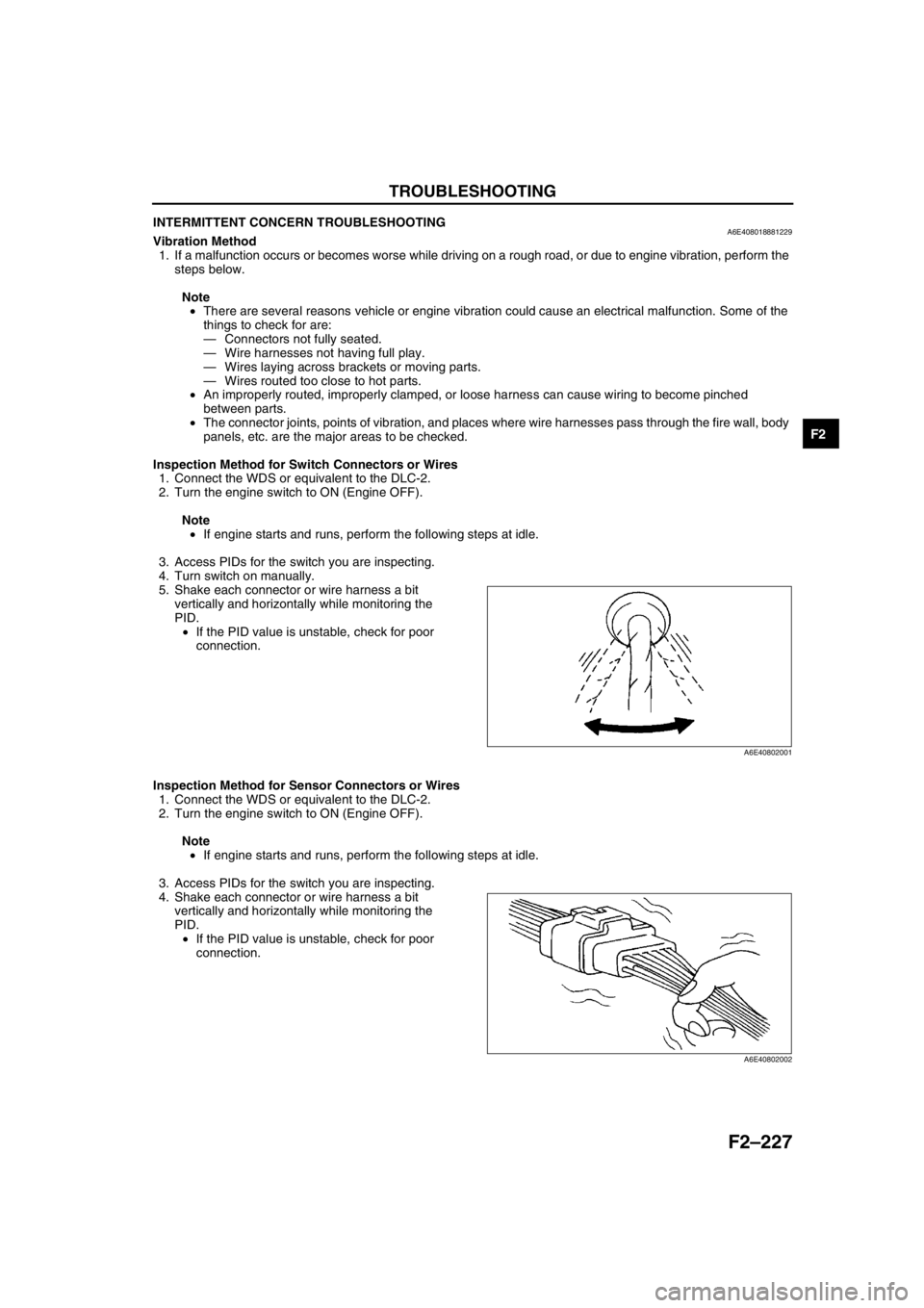
Inspection Method for Switch Connectors or Wires
1. Connect the WDS or equivalent to the DLC-2.
2. Turn the engine switch to ON (Engine OFF).
Note
•If engine starts and runs, perform the following steps at idle.
3. Access PIDs for the switch you are inspecting.
4. Turn switch on manually.
5. Shake each connector or wire harness a bit
vertically and horizontally while monitoring the
PID.
•If the PID value is unstable, check for poor
connection.
Inspection Method for Sensor Connectors or Wires
1. Connect the WDS or equivalent to the DLC-2.
2. Turn the engine switch to ON (Engine OFF).
Note
•If engine starts and runs, perform the following steps at idle.
3. Access PIDs for the switch you are inspecting.
4. Shake each connector or wire harness a bit
vertically and horizontally while monitoring the
PID.
•If the PID value is unstable, check for poor
connection.
A6E40802001
A6E40802002
Page 380 of 909
F2–228
TROUBLESHOOTING
Inspection Method for Sensors
1. Connect the WDS or equivalent to the DLC-2.
2. Turn the engine switch to ON (Engine OFF).
Note
•If the engine starts and runs, perform the following steps at idle.
3. Access PIDs for the switch you are inspecting.
4. Vibrate the sensor slightly with your finger.
•If the PID value is unstable or malfunction occurs, check for poor connection and/or poorly mounted
sensor.
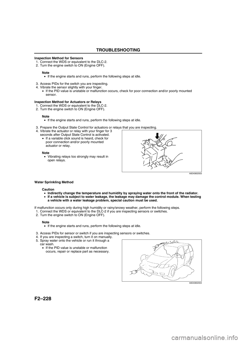
Inspection Method for Actuators or Relays
1. Connect the WDS or equivalent to the DLC-2.
2. Turn the engine switch to ON (Engine OFF).
Note
•If the engine starts and runs, perform the following steps at idle.
3. Prepare the Output State Control for actuators or relays that you are inspecting.
4. Vibrate the actuator or relay with your finger for 3
seconds after Output State Control is activated.
•If a variable click sound is heard, check for
poor connection and/or poorly mounted
actuator or relay.
Note
•Vibrating relays too strongly may result in
open relays.
Water Sprinkling Method
Caution
•Indirectly change the temperature and humidity by spraying water onto the front of the radiator.
•If a vehicle is subject to water leakage, the leakage may damage the control module. When testing
a vehicle with a water leakage problem, special caution must be used.
If malfunction occurs only during high humidity or rainy/snowy weather, perform the following steps.
1. Connect the WDS or equivalent to the DLC-2 if you are inspecting sensors or switches.
2. Turn the engine switch to ON (Engine OFF).
Note
•If the engine starts and runs, perform the following steps at idle.
3. Access PIDs for sensor or switch if you are inspecting sensors or switches.
4. If you are inspecting a switch, turn it on manually.
5. Spray water onto the vehicle or run it through a
car wash.
•If the PID value is unstable or malfunction
occurs, repair or replace part as necessary.
End Of Sie
A6E40802003
A6E40802004
Page 381 of 909

TROUBLESHOOTING
F2–229
F2
ENGINE CONTROL SYSTEM OPERATION INSPECTIONA6E408018881230Intake Shutter Valve Operation Inspection
1. Start the engine and warm up completely.
2. Turn off the A/C switch.
3. Connect the WDS or equivalent to the DLC-2.
4. Monitor the following PIDs using the WDS or equivalent.
—If not as specified, inspect each sensor and related harness.
ECT PID
Above 60 °C {140 °F}
MAF PID
1.7—1.9 V
RPM PID
725—825 rpm
Note
•The position of the shutter valve, VSC shutter valve and EGR valve may not be as specified when idle
speed is maintained for several minutes. If this occurs, briefly increase engine speed to 1,500 rpm and
then re-check the position at idle speed.
5. Increase the engine speed and inspect that the intake shutter valve position changes as specified.
•If not as specified, inspect the following.
—Vacuum hose
—Intake shutter solenoid valve actuator
—Intake shutter solenoid valve and related harness.
Specification
Guide Blade Actuator Operation Inspection
1. Start the engine and warm up completely.
2. Verify that the A/C switch is off.
3. Connect the WDS or equivalent to the DLC-2.
4. Monitor the following PIDs using the WDS or equivalent.
—If not as specified, inspect each sensor and related harness.
ECT PID
Above 60 °C {140 °F}
MAF PID
1.7—1.9 V
RPM PID
725—825 rpm
ACSW PID
OFF
5. Inspect that the guide blade actuator position changes as specified.
•If not as specified, inspect the following.
—Vacuum hose
—Guide blade actuator
—VBC solenoid valve and related harness.
Specification
*1 : Just after turning engine switch off
*2 : 0 to 5 seconds after turning engine switch to OFF
*3 : Guide blade actuator begins to pull back
Engine speed (rpm) Intake shutter valve position
775 Halfway open
1,800 Fully open
2,500 Fully open
Above 3,400 Fully open
Engine switch
positionEngine speed
(rpm)Guide blade
actuator position
ON 775 Closed
OFF
*10*3Closed
OFF
*20 Open
Page 389 of 909

G–6
CHARGING SYSTEM
BATTERY INSPECTIONA6E471018520202MZR-CD (RF Turbo)
Battery
1. Inspect the battery with the following procedure.
Load test chart
Battery positive voltage with load
Back-up Current
1. Verify that the engine switch is off and that the engine key has been removed.
2. Disconnect the negative battery cable.
Caution
•Operating electrical loads while measuring the back-up current can damage the circuit tester.
3. Measure the back-up current between the negative battery terminal and the negative battery cable.
(1) If the current exceeds the maximum, remove the fuses in the main fuse block and the fuse block one by
one while measuring the back-up current.
(2) Inspect and repair harnesses and connectors on the fuse where the current has been reduced.
Back-up current
20 mA max.
End Of Sie
BATTERY RECHARGINGA6E471018520203MZR-CD (RF Turbo)
Caution
•To avoid damage to the battery, do not quick charge for over 30 min.
•When disconnecting the battery, remove the negative cable first and install it last to prevent
damage to electrical components or the battery.
•To avoid deformation or damage to the battery, remove the battery plugs while charging the
battery.
Step Inspection Result Action
1Measure open circuit
voltage of battery.Above
12.4 VGo to Step
3.
Below
12.4 VGo to next
step.
2Quick-charge for 30 min.
and recheck voltage.Above
12.4 VGo to next
step.
Below
12.4 VReplace
battery.
3Apply load test (see load
test chart) to battery using a
battery load tester and
record battery voltage after
15 s. Is voltage more than
specification?YesBattery
okay.
NoReplace
battery.
Battery Load (A)
95D31L (64) 250
115D31L (70) 320
Approximate battery temp. Minimum voltage (V)
21°C {70°F} 9.6
15°C {60°F} 9.5
10°C {50°F} 9.4
4°C {40°F} 9.3
–1°C {30°F} 9.1
–7°C {20°F} 8.9
–12°C {10°F} 8.7
–18°C {0°F} 8.5
Page 494 of 909
AUTOMATIC TRANSAXLE
K2–79
K2
Automatic Transaxle Fluid (ATF) Level Inspection
Caution
•The ATF amount varies according to ATF's temperature. Therefore, when checking the ATF level or
replacing the ATF, use a thermometer to measure the temperature then adjust the ATF amount to
the specified level according to the specified temperature.
1. Park the vehicle on level ground.
2. Apply the parking brake and position wheel chocks securely to prevent the vehicle from rolling.
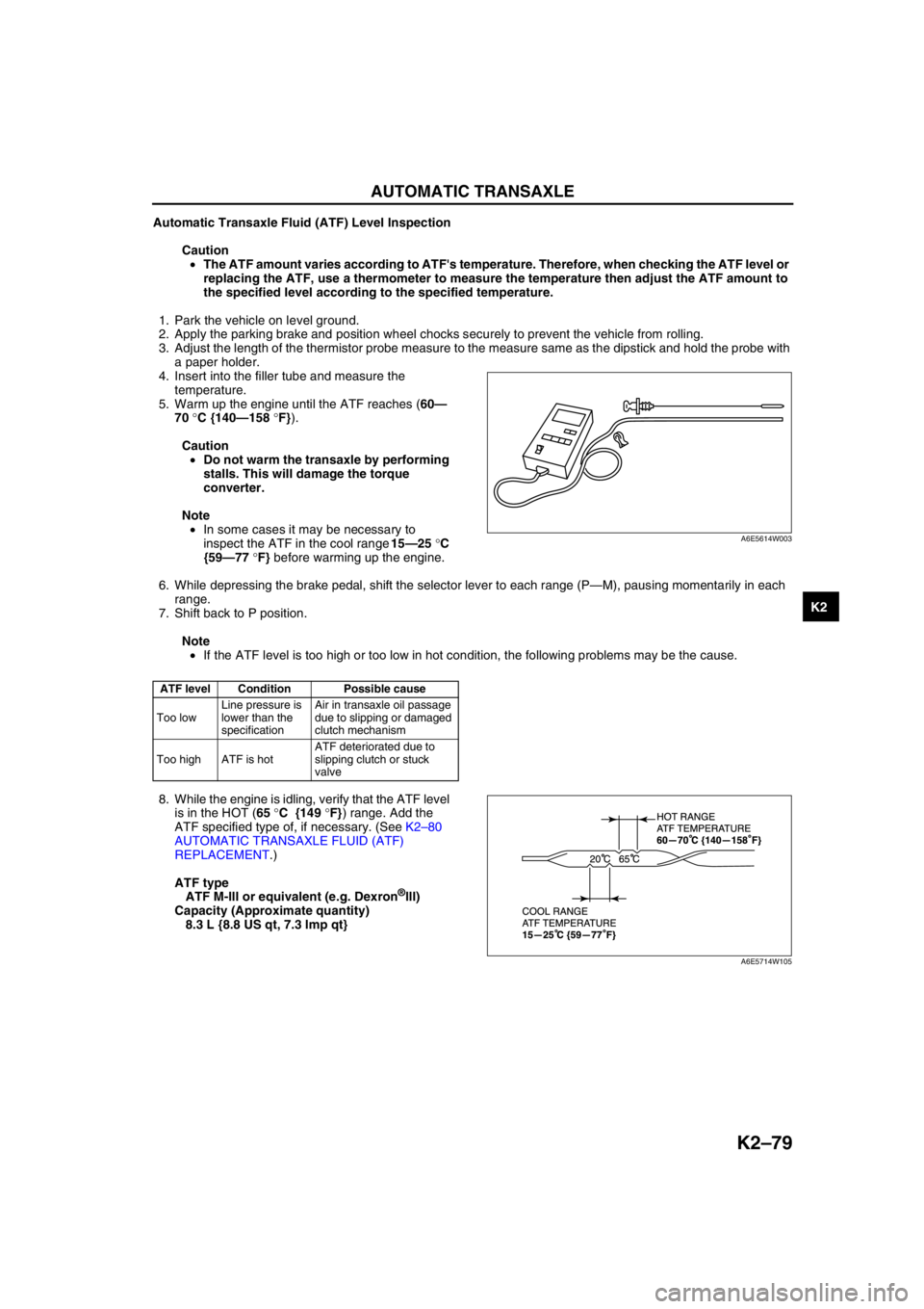
3. Adjust the length of the thermistor probe measure to the measure same as the dipstick and hold the probe with
a paper holder.
4. Insert into the filler tube and measure the
temperature.
5. Warm up the engine until the ATF reaches (60—
70 °C {140—158 °F}).
Caution
•Do not warm the transaxle by performing
stalls. This will damage the torque
converter.
Note
•In some cases it may be necessary to
inspect the ATF in the cool range 15—25 °C
{59—77 °F} before warming up the engine.
6. While depressing the brake pedal, shift the selector lever to each range (P—M), pausing momentarily in each
range.
7. Shift back to P position.
Note
•If the ATF level is too high or too low in hot condition, the following problems may be the cause.
8. While the engine is idling, verify that the ATF level
is in the HOT (65 °C {149 °F}) range. Add the
ATF specified type of, if necessary. (See K2–80
AUTOMATIC TRANSAXLE FLUID (ATF)
REPLACEMENT.)
ATF type
ATF M-III or equivalent (e.g. Dexron
®III)
Capacity (Approximate quantity)
8.3 L {8.8 US qt, 7.3 Imp qt}
End Of Sie
ATF level Condition Possible cause
Too lowLine pressure is
lower than the
specificationAir in transaxle oil passage
due to slipping or damaged
clutch mechanism
Too high ATF is hotATF deteriorated due to
slipping clutch or stuck
valve
A6E5614W003
A6E5714W105