check engine MAZDA 6 2002 Suplement Manual PDF
[x] Cancel search | Manufacturer: MAZDA, Model Year: 2002, Model line: 6, Model: MAZDA 6 2002Pages: 909, PDF Size: 17.16 MB
Page 585 of 909
K2–170
ON-BOARD DIAGNOSTIC
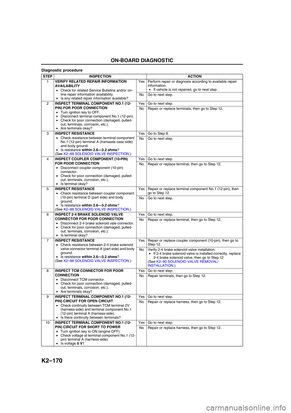
Diagnostic procedure
STEP INSPECTION ACTION
1VERIFY RELATED REPAIR INFORMATION
AVAILABILITY
•Check for related Service Bulletins and/or on-
line repair information availability.
•Is any related repair information available?Yes Perform repair or diagnosis according to available repair
information.
•If vehicle is not repaired, go to next step.
No Go to next step.
2INSPECT TERMINAL COMPONENT NO.1 (12-
PIN) FOR POOR CONNECTION
•Turn ignition key to OFF.
•Disconnect terminal component No.1 (12-pin).
•Check for poor connection (damaged, pulled-
out, terminals, corrosion, etc.).
•Are terminals okay?Yes Go to next step.
No Repair or replace terminals, then go to Step 12.
3INSPECT RESISTANCE
•Check resistance between terminal component
No.1 (12-pin) terminal A (transaxle case side)
and body ground.
•Is resistance within 2.6—3.2 ohms?
(See K2–88 SOLENOID VALVE INSPECTION.)Yes Go to Step 8.
No Go to next step.
4INSPECT COUPLER COMPONENT (10-PIN)
FOR POOR CONNECTION
•Disconnect coupler component (10-pin)
connector.
•Check for poor connection (damaged, pulled-
out, terminals, corrosion, etc.).
•Is terminal okay?Yes Go to next step.
No Repair or replace terminal, then go to Step 12.
5INSPECT RESISTANCE
•Check resistance between coupler component
(10-pin) terminal D (part side) and body
ground.
•Is resistance within 2.6—3.2 ohms?
(See K2–88 SOLENOID VALVE INSPECTION.)Yes Repair or replace terminal component No.1 (12-pin), then
go to Step 12.
No Go to next step.
6INSPECT 2-4 BRAKE SOLENOID VALVE
CONNECTOR FOR POOR CONNECTION
•Disconnect 2-4 brake solenoid vale connector.
•Check for poor connection (damaged, pulled-
out, terminals, corrosion, etc.).
•Is terminal okay?Yes Go to next step.
No Repair or replace terminal, then go to Step 12.
7INSPECT RESISTANCE
•Check resistance between 2-4 brake solenoid
valve connector terminal A (part side) and body
ground.
•Is resistance within 2.6—3.2 ohms?
(See K2–88 SOLENOID VALVE INSPECTION.)Yes Repair or replace coupler component (10-pin), then go to
Step 12.
No Verify 2-4 brake solenoid valve installation.
•If 2-4 brake solenoid valve is installed correctly, replace
2-4 brake solenoid valve, then go to Step 12
(See K2–90 SOLENOID VALVE REMOVAL/
INSTALLATION.)
8INSPECT TCM CONNECTOR FOR POOR
CONNECTION
•Disconnect TCM connector.
•Check for poor connection (damaged, pulled-
out, terminals, corrosion, etc.).
•Are terminals okay?Yes Go to next step.
No Repair terminals, then go to Step 12.
9INSPECT TERMINAL COMPONENT NO.1 (12-
PIN) CIRCUIT FOR OPEN CIRCUIT
•Check continuity between TCM terminal 2V
(harness-side) and terminal component No.1
(12-pin) terminal A (harness-side).
•Is there continuity between terminals?Yes Go to next step.
No Repair or replace harness, then go to Step 12.
10INSPECT TERMINAL COMPONENT NO.1 (12-
PIN) CIRCUIT FOR SHORT TO POWER
•Turn ignition key to ON (engine OFF).
•Check voltage at terminal component No.1 (12-
pin) terminal A (harness-side).
•Is voltage 0 V?Yes Go to next step.
No Repair or replace harness, then go to Step 12.
Page 589 of 909
K2–174
ON-BOARD DIAGNOSTIC
End Of Sie
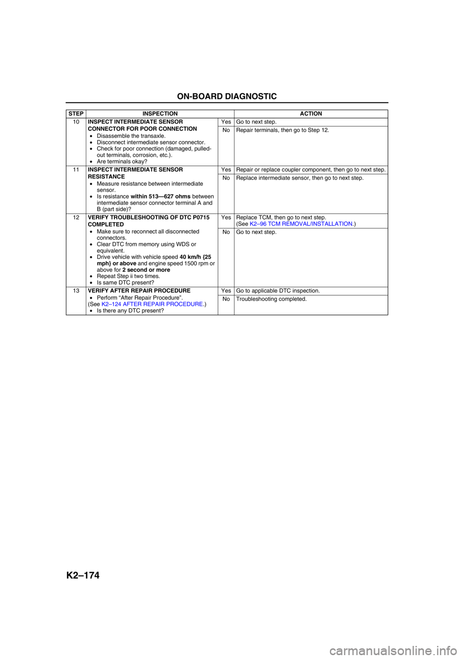
10INSPECT INTERMEDIATE SENSOR
CONNECTOR FOR POOR CONNECTION
•Disassemble the transaxle.
•Disconnect intermediate sensor connector.
•Check for poor connection (damaged, pulled-
out terminals, corrosion, etc.).
•Are terminals okay?Yes Go to next step.
No Repair terminals, then go to Step 12.
11INSPECT INTERMEDIATE SENSOR
RESISTANCE
•Measure resistance between intermediate
sensor.
•Is resistance within 513—627 ohms between
intermediate sensor connector terminal A and
B (part side)?Yes Repair or replace coupler component, then go to next step.
No Replace intermediate sensor, then go to next step.
12VERIFY TROUBLESHOOTING OF DTC P0715
COMPLETED
•Make sure to reconnect all disconnected
connectors.
•Clear DTC from memory using WDS or
equivalent.
•Drive vehicle with vehicle speed 40 km/h {25
mph} or above and engine speed 1500 rpm or
above for 2 second or more
•Repeat Step ii two times.
•Is same DTC present?Yes Replace TCM, then go to next step.
(See K2–96 TCM REMOVAL/INSTALLATION.)
No Go to next step.
13VERIFY AFTER REPAIR PROCEDURE
•Perform “After Repair Procedure”.
(See K2–124 AFTER REPAIR PROCEDURE.)
•Is there any DTC present?Yes Go to applicable DTC inspection.
No Troubleshooting completed. STEP INSPECTION ACTION
Page 591 of 909
K2–176
ON-BOARD DIAGNOSTIC
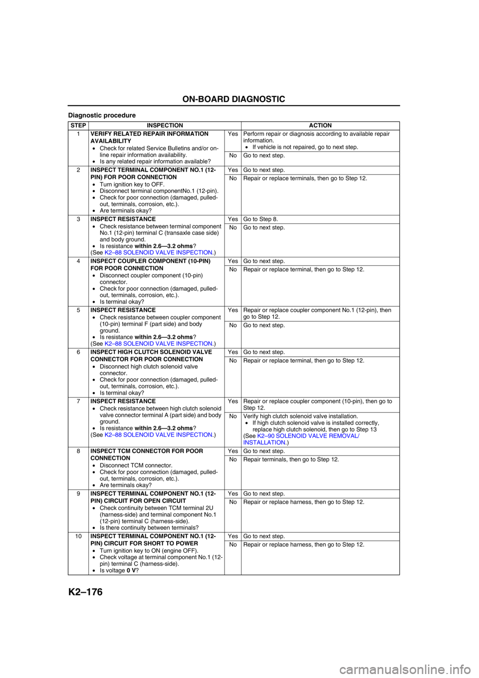
Diagnostic procedure
STEP INSPECTION ACTION
1VERIFY RELATED REPAIR INFORMATION
AVAILABILITY
•Check for related Service Bulletins and/or on-
line repair information availability.
•Is any related repair information available?Yes Perform repair or diagnosis according to available repair
information.
•If vehicle is not repaired, go to next step.
No Go to next step.
2INSPECT TERMINAL COMPONENT NO.1 (12-
PIN) FOR POOR CONNECTION
•Turn ignition key to OFF.
•Disconnect terminal componentNo.1 (12-pin).
•Check for poor connection (damaged, pulled-
out, terminals, corrosion, etc.).
•Are terminals okay?Yes Go to next step.
No Repair or replace terminals, then go to Step 12.
3INSPECT RESISTANCE
•Check resistance between terminal component
No.1 (12-pin) terminal C (transaxle case side)
and body ground.
•Is resistance within 2.6—3.2 ohms?
(See K2–88 SOLENOID VALVE INSPECTION.)Yes Go to Step 8.
No Go to next step.
4INSPECT COUPLER COMPONENT (10-PIN)
FOR POOR CONNECTION
•Disconnect coupler component (10-pin)
connector.
•Check for poor connection (damaged, pulled-
out, terminals, corrosion, etc.).
•Is terminal okay?Yes Go to next step.
No Repair or replace terminal, then go to Step 12.
5INSPECT RESISTANCE
•Check resistance between coupler component
(10-pin) terminal F (part side) and body
ground.
•Is resistance within 2.6—3.2 ohms?
(See K2–88 SOLENOID VALVE INSPECTION.)Yes Repair or replace coupler component No.1 (12-pin), then
go to Step 12.
No Go to next step.
6INSPECT HIGH CLUTCH SOLENOID VALVE
CONNECTOR FOR POOR CONNECTION
•Disconnect high clutch solenoid valve
connector.
•Check for poor connection (damaged, pulled-
out, terminals, corrosion, etc.).
•Is terminal okay?Yes Go to next step.
No Repair or replace terminal, then go to Step 12.
7INSPECT RESISTANCE
•Check resistance between high clutch solenoid
valve connector terminal A (part side) and body
ground.
•Is resistance within 2.6—3.2 ohms?
(See K2–88 SOLENOID VALVE INSPECTION.)Yes Repair or replace coupler component (10-pin), then go to
Step 12.
No Verify high clutch solenoid valve installation.
•If high clutch solenoid valve is installed correctly,
replace high clutch solenoid, then go to Step 13
(See K2–90 SOLENOID VALVE REMOVAL/
INSTALLATION.)
8INSPECT TCM CONNECTOR FOR POOR
CONNECTION
•Disconnect TCM connector.
•Check for poor connection (damaged, pulled-
out, terminals, corrosion, etc.).
•Are terminals okay?Yes Go to next step.
No Repair terminals, then go to Step 12.
9INSPECT TERMINAL COMPONENT NO.1 (12-
PIN) CIRCUIT FOR OPEN CIRCUIT
•Check continuity between TCM terminal 2U
(harness-side) and terminal component No.1
(12-pin) terminal C (harness-side).
•Is there continuity between terminals?Yes Go to next step.
No Repair or replace harness, then go to Step 12.
10INSPECT TERMINAL COMPONENT NO.1 (12-
PIN) CIRCUIT FOR SHORT TO POWER
•Turn ignition key to ON (engine OFF).
•Check voltage at terminal component No.1 (12-
pin) terminal C (harness-side).
•Is voltage 0 V?Yes Go to next step.
No Repair or replace harness, then go to Step 12.
Page 745 of 909
P–12
CONVENTIONAL BRAKE SYSTEM
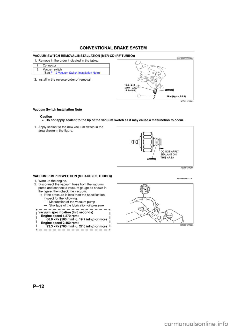
VACUUM SWITCH REMOVAL/INSTALLATION (MZR-CD (RF TURBO))A6E6912663902021. Remove in the order indicated in the table.
2. Install in the reverse order of removal.
Vacuum Switch Installation Note Caution• Do not apply sealant to the lip of the vacuum switch as it may cause a malfunction to occur.
1. Apply sealant to the new vacuum switch in the area shown in the figure.
End Of Sie
VACUUM PUMP INSPECTION (MZR-CD (RF TURBO))A6E6912187772011. Warn up the engine.
2. Disconnect the vacuum hose from the vacuum pump and connect a vacuum gauge as shown in
the figure, then check the vacuum.• If the pressure is less than the specification,
inspect for the following.
— Malfunction of the vacuum pump
— Shortage of the lubrication oil pressure
Vacuum specification (In 8 seconds) Engine speed 1,270 rpm: 66.6 kPa {500 mmHg, 19.7 inHg} or more
Engine speed 2,450 rpm: 93.3 kPa {700 mmHg, 27.6 inHg} or more
End Of Sie
1 Connector
2 Vacuum switch (See P –12 Vacu um S w itch Ins tal lat ion Note )
SEALANT
1
219.6—24.5
{2.00—2.49,
14.5—18.0}
N·m {kgf·m, ft·lbf}
A6E6912W205
SEALANT
DO NOT APPLY
SEALANT ON
THIS AREA
A6E6912W206
AME6912W006
Page 750 of 909
PARKING BRAKE SYSTEM, DYNAMIC STABILITY CONTROL
P–17
P
PARKING BRAKE (LEVER TYPE) ADJUSTMENTA6E6914440002011. Start the engine and depress the brake pedal several times.
2. Stop the engine.
3. For the 2WD model, remove the rear ashtray case behind the center console
4. For the 4WD model, remove the 4 screws (back side) and pull up the rear of the center console, then remove
the rear ashtray case.
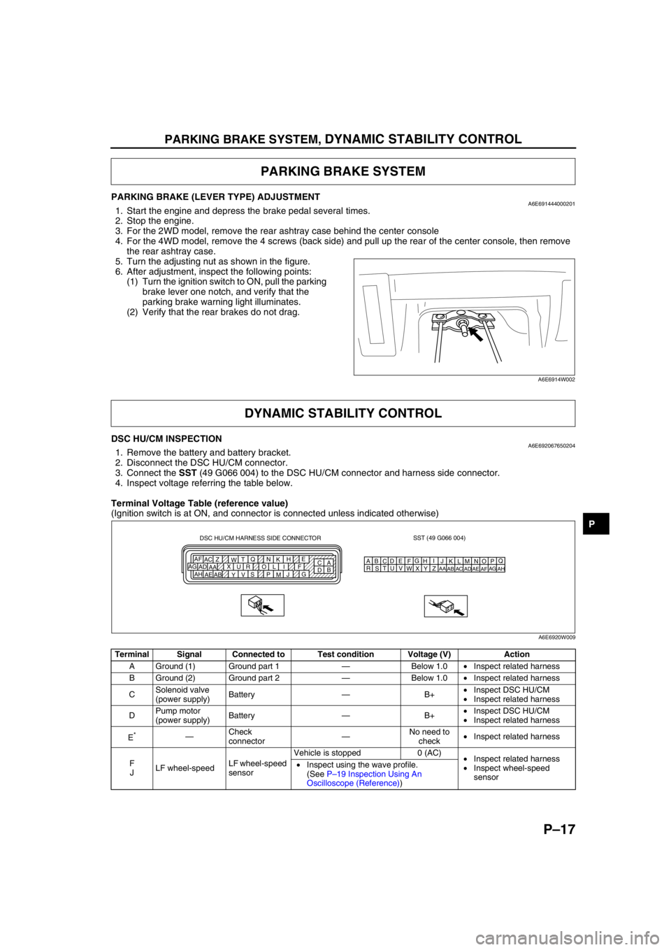
5. Turn the adjusting nut as shown in the figure.
6. After adjustment, inspect the following points:
(1) Turn the ignition switch to ON, pull the parking
brake lever one notch, and verify that the
parking brake warning light illuminates.
(2) Verify that the rear brakes do not drag.
End Of Sie
DSC HU/CM INSPECTIONA6E6920676502041. Remove the battery and battery bracket.
2. Disconnect the DSC HU/CM connector.
3. Connect the SST (49 G066 004) to the DSC HU/CM connector and harness side connector.
4. Inspect voltage referring the table below.
Terminal Voltage Table (reference value)
(Ignition switch is at ON, and connector is connected unless indicated otherwise)
PARKING BRAKE SYSTEM
A6E6914W002
DYNAMIC STABILITY CONTROL
Terminal Signal Connected to Test condition Voltage (V) Action
A Ground (1) Ground part 1—Below 1.0•Inspect related harness
B Ground (2) Ground part 2—Below 1.0•Inspect related harness
CSolenoid valve
(power supply)Battery—B+•Inspect DSC HU/CM
•Inspect related harness
DPump motor
(power supply)Battery—B+•Inspect DSC HU/CM
•Inspect related harness
E
*—Check
connector—No need to
check•Inspect related harness
F
JLF wheel-speedLF wheel-speed
sensorVehicle is stopped 0 (AC)
•Inspect related harness
•Inspect wheel-speed
sensor •Inspect using the wave profile.
(See P–19 Inspection Using An
Oscilloscope (Reference))
SST (49 G066 004)
AQ
B
CDE
FG
HI
J DSC HU/CM HARNESS SIDE CONNECTOR
A
C E
H
K N Q
T
W Z AC AF
F I L O R U X
AA AD AG
G
J
M P S
V
Y AB AE AHB
DKN
T
WZ
AC
AFLO
RU
XAA
ADAGMP
SV
YAB
AEAH
A6E6920W009
Page 760 of 909

ON-BOARD DIAGNOSTIC
P–27
P
Diagnostic procedure
End Of Sie
DTC C1949, C1950A6E697067650203
Caution
•When attaching the tester lead to the DSC HU/CM connector, the SST (49 G066 004) must be used.
STEP INSPECTION ACTION
1CHECK FOR PCM FOR DTCs
•Turn ignition key to OFF.
•Connect WDS or equivalent to DLC-2
•Turn ignition key to ON (engine OFF).
•Is DTC for engine control system obtained?Yes Follow inspection procedures for engine control system.
No Go to next step.
2MONITOR CAN SIGNAL
•Access PID RPM and TP using WDS or
equivalent.
•Are engine speed and throttle position within
specification?Yes Go to next step.
No Follow inspection procedures for engine control system.
3VERIFY TROUBLESHOOTING COMPLETED
•Make sure to reconnect all disconnected
connectors.
•Clear DTC from memory.
•Start engine.
•Is same DTC present?Yes Replace DSC HU/CM, then go to next step.
No Troubleshooting completed.
DTC C1949, C1950 Combine sensor (forward G-sensor)
DETECTION
CONDITION•C1949:
—Monitor voltage of forward-G sensor is detected at 4.5 V or more, or 0.5 V or less.
—Monitor voltage difference of 0.4 V or more within 1 cycle is detected 8 times in 1 second.
•C1950:
—Forward-G sensor 0-point correction value is default or more
—Output voltage value from G sensor remains absolutely unchanged
—Difference between estimated G-force calculated from 2 channels exceeds specification
POSSIBLE
CAUSE•Open circuit in harness between combine sensor terminal C and DSC HU/CM terminal P
•Open circuit, short to power, or short to ground in harness between DSC HU/CM terminal V and
combine sensor terminal A
•Open circuit, short to power, or short to ground in harness between DSC HU/CM terminal S and
combine sensor terminal F
•Open circuit in harness between combine sensor terminal E and DSC HU/CM terminal Y
•Malfunction of combine sensor
Page 767 of 909
REAR SUSPENSION
R–5
R
SUSPENSION CONTROL SYSTEMA6E741601013201Outline
•The self-leveling suspension is a system that adjusts the vehicle height according the amount of vehicle load.
This system will raise the rear of a vehicle, lowered due to a load placed on it, to the designated load level
* after
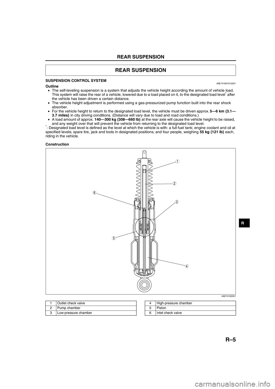
the vehicle has been driven a certain distance.
•The vehicle height adjustment is performed using a gas-pressurized pump function built into the rear shock
absorber.
•For the vehicle height to return to the designated load level, the vehicle must be driven approx. 5—6 km {3.1—
3.7 miles} in city driving conditions. (Distance will vary due to load and road conditions.)
•A load amount of approx. 140—300 kg {308—660 lb} at the rear axle will cause the vehicle height to be raised,
and any weight over that will prevent the vehicle from returning to the designated load level.
*: Designated load level is defined as the level at which the vehicle is with: a full fuel tank; engine coolant and oil at
specified levels; spare tire, jack and tools in designated positions; and four people, weighing 55 kg {121 lb} each,
riding in the vehicle.
Construction
.
REAR SUSPENSION
5
4
3
6
1
2
A6E74162001
1 Outlet check valve
2 Pump chamber
3 Low-pressure chamber4 High-pressure chamber
5Piston
6 Inlet check valve