check engine MAZDA 6 2002 Suplement User Guide
[x] Cancel search | Manufacturer: MAZDA, Model Year: 2002, Model line: 6, Model: MAZDA 6 2002Pages: 909, PDF Size: 17.16 MB
Page 156 of 909
F2–4
OUTLINE
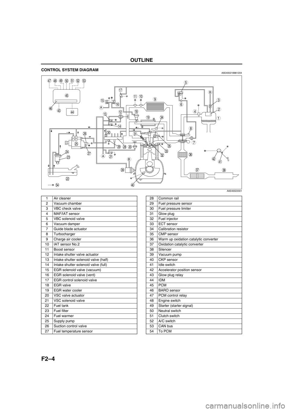
CONTROL SYSTEM DIAGRAMA6E400218881204
.
End Of Sie
5
4
3
6
1
2
8
7
910
13
11
12
19
18
17
1516
14
202928
27
25
26
24
2321
22
30
393837
35
3633
31
32
40
34
494847
45
464443
4142
50
54
515253
A
A
BB
A6E40022001
1 Air cleaner
2 Vacuum chamber
3 VBC check valve
4 MAF/IAT sensor
5 VBC solenoid valve
6 Vacuum damper
7 Guide blade actuator
8 Turbocharger
9 Charge air cooler
10 IAT sensor No.2
11 Boost sensor
12 Intake shutter valve actuator
13 Intake shutter solenoid valve (half)
14 Intake shutter solenoid valve (full)
15 EGR solenoid valve (vacuum)
16 EGR solenoid valve (vent)
17 EGR control solenoid valve
18 EGR valve
19 EGR water cooler
20 VSC valve actuator
21 VSC solenoid valve
22 Fuel tank
23 Fuel filter
24 Fuel warmer
25 Supply pump
26 Suction control valve
27 Fuel temperature sensor28 Common rail
29 Fuel pressure sensor
30 Fuel pressure limiter
31 Glow plug
32 Fuel injector
33 ECT sensor
34 Calibration resistor
35 CMP sensor
36 Warm up oxidation catalytic converter
37 Oxidation catalytic converter
38 Silencer
39 Vacuum pump
40 CKP sensor
41 Idle switch
42 Accelerator position sensor
43 Glow plug relay
44 IDM
45 PCM
46 BARO sensor
47 PCM control relay
48 Engine switch
49 Starter (starter signal)
50 Neutral switch
51 Clutch switch
52 A/C switch
53 CAN bus
54 To PCM
Page 166 of 909
F2–14
EMISSION SYSTEM
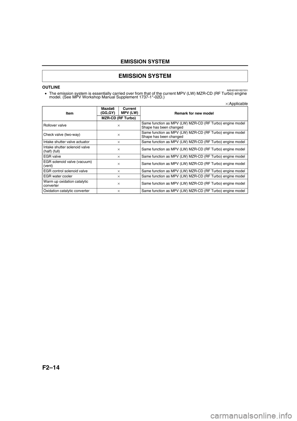
OUTLINEA6E401601007201•The emission system is essentially carried over from that of the current MPV (LW) MZR-CD (RF Turbo) engine
model. (See MPV Workshop Manual Supplement 1737-1*-02D.)
×:Applicable
End Of Sie
EMISSION SYSTEM
ItemMazda6
(GG,GY)Current
MPV (LW)
Remark for new model
MZR-CD (RF Turbo)
Rollover valve×Same function as MPV (LW) MZR-CD (RF Turbo) engine model
Shape has been changed
Check valve (two-way)×Same function as MPV (LW) MZR-CD (RF Turbo) engine model
Shape has been changed
Intake shutter valve actuator×Same function as MPV (LW) MZR-CD (RF Turbo) engine model
Intake shutter solenoid valve
(half) (full)×Same function as MPV (LW) MZR-CD (RF Turbo) engine model
EGR valve×Same function as MPV (LW) MZR-CD (RF Turbo) engine model
EGR solenoid valve (vacuum)
(vent)×Same function as MPV (LW) MZR-CD (RF Turbo) engine model
EGR control solenoid valve×Same function as MPV (LW) MZR-CD (RF Turbo) engine model
EGR water cooler×Same function as MPV (LW) MZR-CD (RF Turbo) engine model
Warm up oxidation catalytic
converter×Same function as MPV (LW) MZR-CD (RF Turbo) engine model
Oxidation catalytic converter×Same function as MPV (LW) MZR-CD (RF Turbo) engine model
Page 167 of 909
EMISSION SYSTEM
F2–15
F2
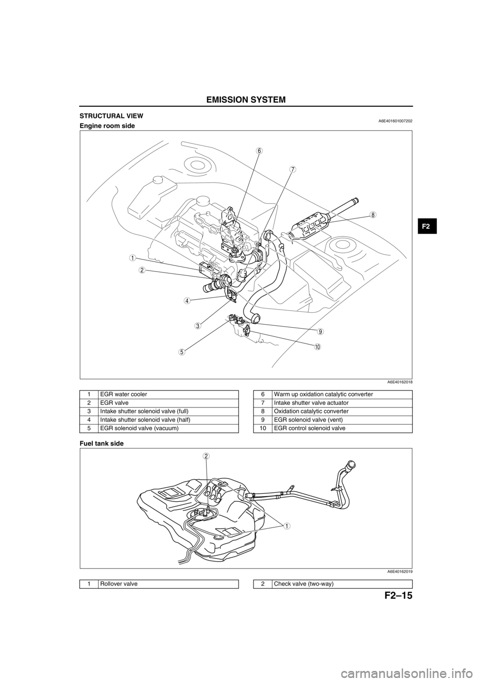
STRUCTURAL VIEWA6E401601007202Engine room side
.
Fuel tank side
.
9
8
7
5
4
3
10
6
2
1
A6E40162018
1EGR water cooler
2EGR valve
3 Intake shutter solenoid valve (full)
4 Intake shutter solenoid valve (half)
5 EGR solenoid valve (vacuum)6 Warm up oxidation catalytic converter
7 Intake shutter valve actuator
8 Oxidation catalytic converter
9 EGR solenoid valve (vent)
10 EGR control solenoid valve
1
2
A6E40162019
1 Rollover valve2 Check valve (two-way)
Page 181 of 909
LOCATION INDEX
F2–29
F2
End Of Sie
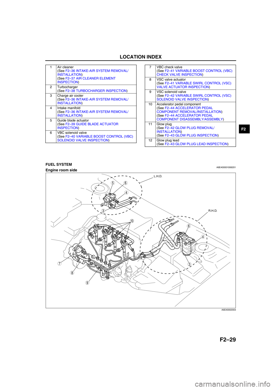
FUEL SYSTEMA6E400001006201Engine room side
1 Air cleaner
(See F2–36 INTAKE-AIR SYSTEM REMOVAL/
INSTALLATION)
(See F2–37 AIR CLEANER ELEMENT
INSPECTION)
2 Turbocharger
(See F2–38 TURBOCHARGER INSPECTION)
3 Charge air cooler
(See F2–36 INTAKE-AIR SYSTEM REMOVAL/
INSTALLATION)
4 Intake manifold
(See F2–36 INTAKE-AIR SYSTEM REMOVAL/
INSTALLATION)
5 Guide blade actuator
(See F2–39 GUIDE BLADE ACTUATOR
INSPECTION)
6 VBC solenoid valve
(See F2–40 VARIABLE BOOST CONTROL (VBC)
SOLENOID VALVE INSPECTION)7 VBC check valve
(See F2–41 VARIABLE BOOST CONTROL (VBC)
CHECK VALVE INSPECTION)
8 VSC valve actuator
(See F2–41 VARIABLE SWIRL CONTROL (VSC)
VALVE ACTUATOR INSPECTION)
9 VSC solenoid valve
(See F2–42 VARIABLE SWIRL CONTROL (VSC)
SOLENOID VALVE INSPECTION)
10 Accelerator pedal component
(See F2–44 ACCELERATOR PEDAL
COMPONENT REMOVAL/INSTALLATION)
(See F2–44 ACCELERATOR PEDAL
COMPONENT DISASSEMBLY/ASSEMBLY)
11 Glow plug
(See F2–42 GLOW PLUG REMOVAL/
INSTALLATION)
(See F2–43 GLOW PLUG INSPECTION)
12 Glow plug lead
(See F2–43 GLOW PLUG LEAD INSPECTION)
9
8
7
5
4
3
6
10
6
4
3
L.H.D.
R.H.D.
A6E40002003
Page 187 of 909
ENGINE TUNE-UP, INTAKE-AIR SYSTEM
F2–35
F2
Injection Amount Correction
Note
•Perform this procedure at the recommended interval as described under “Fuel injection system” in
“SCHEDULED MAINTENANCE.”
1. Perform “Engine Tune-up Preparation”. (See F2–34 ENGINE TUNE-UP PREPARATION.)
2. Perform “Injection Amount Correction” using the WDS or equivalent.
MAF Correction
Note
•Perform this procedure after replacing the MAF/IAT sensor or at the recommended interval as described
under “E.G.R. system” in “SCHEDULED MAINTENANCE.”
1. Perform “Engine Tune-up Preparation”. (See F2–34 ENGINE TUNE-UP PREPARATION.)
2. Perform “MAF Correction” using the WDS or equivalent.
End Of Sie
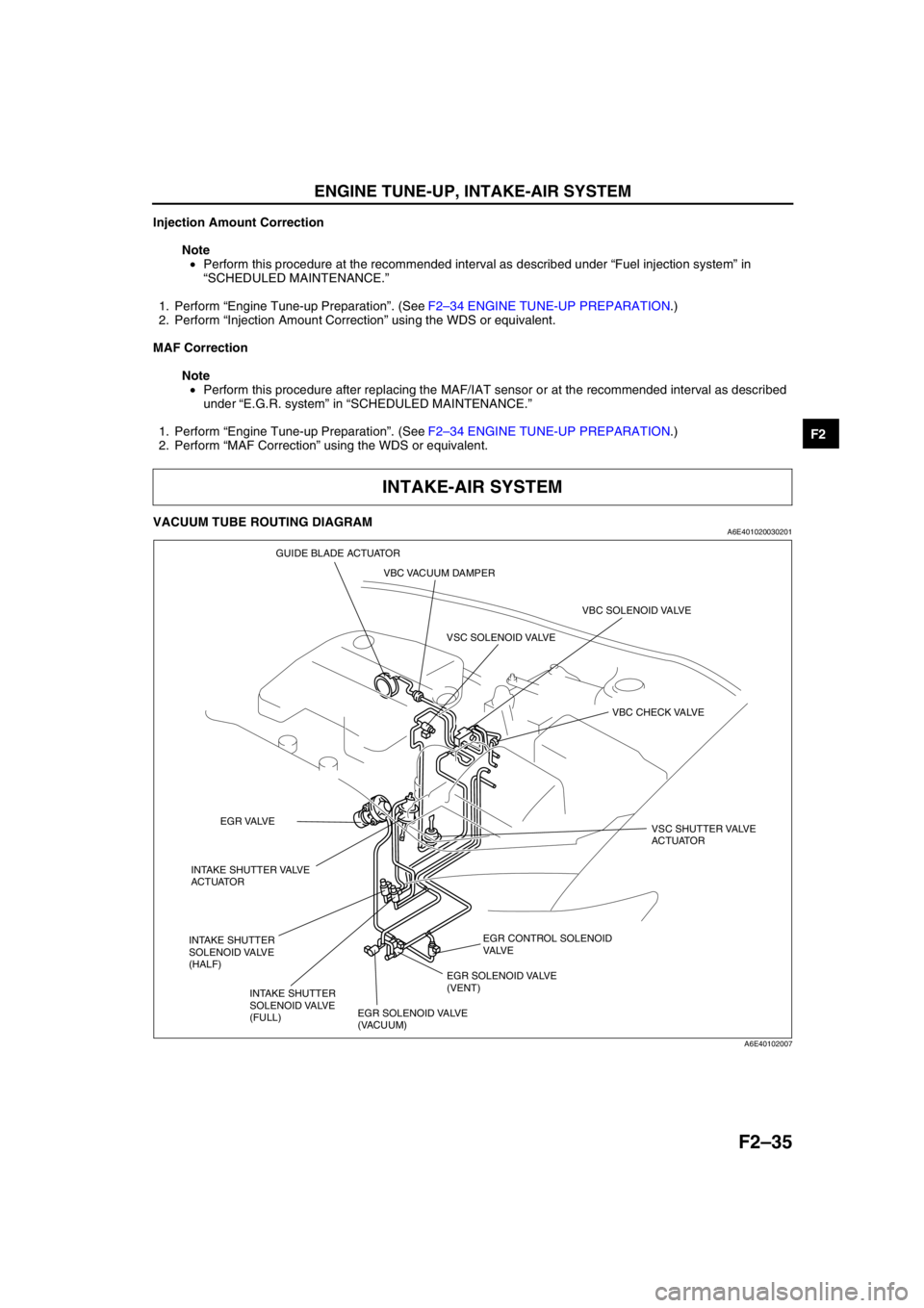
VACUUM TUBE ROUTING DIAGRAMA6E401020030201
End Of Sie
INTAKE-AIR SYSTEM
EGR CONTROL SOLENOID
VA LV E
VBC SOLENOID VALVE
VBC CHECK VALVE
EGR SOLENOID VALVE
(VACUUM)EGR SOLENOID VALVE
(VENT) VSC SOLENOID VALVE
VSC SHUTTER VALVE
ACTUATOR
INTAKE SHUTTER VALVE
ACTUATOREGR VALVE
INTAKE SHUTTER
SOLENOID VALVE
(HALF)
INTAKE SHUTTER
SOLENOID VALVE
(FULL)VBC VACUUM DAMPER GUIDE BLADE ACTUATOR
A6E40102007
Page 188 of 909
F2–36
INTAKE-AIR SYSTEM
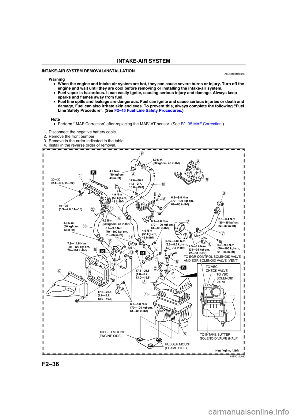
INTAKE-AIR SYSTEM REMOVAL/INSTALLATIONA6E401001005203
Warning
•When the engine and intake-air system are hot, they can cause severe burns or injury. Turn off the
engine and wait until they are cool before removing or installing the intake-air system.
•Fuel vapor is hazardous. It can easily ignite, causing serious injury and damage. Always keep
sparks and flames away from fuel.
•Fuel line spills and leakage are dangerous. Fuel can ignite and cause serious injuries or death and
damage, Fuel can also irritate skin and eyes. To prevent this, always complete the following “Fuel
Line Safety Procedure”. (See F2–45 Fuel Line Safety Procedures.)
Note
•Perform “ MAF Correction” after replacing the MAF/IAT sensor. (See F2–35 MAF Correction.)
1. Disconnect the negative battery cable.
2. Remove the front bumper.
3. Remove in the order indicated in the table.
4. Install in the reverse order of removal.
.
A
A
C
C
B
B
20—30
{2.1—3.1, 15—22}
19—25
{1.9—2.6, 14—18}6.9—9.8 N·m
{70—100 kgf·cm,
61—86 in·lbf}
2.5—3.4 N·m
{25—35 kgf·cm,
22—30 in·lbf}
6.9—9.8 N·m
{70—100 kgf·cm,
61—86 in·lbf} 7.8—11.8 N·m
{80—120 kgf·cm,
70—104 in·lbf}
6.9—9.8 N·m
{70—100 kgf·cm,
61—86 in·lbf} 17.6—26.5
{1.8—2.7,
13.0—19.8}6.9—9.8 N·m
{70—100 kgf·cm,
61—86 in·lbf}
6.9—9.8 N·m
{70—100 kgf·cm,
61—86 in·lbf}
2.5—3.4 N·m
{25—35 kgf·cm,
22—30 in·lbf}
TO EGR CONTROL SOLENOID VALVE
AND EGR SOLENOID VALVE (VENT)
TO VBC
CHECK VALVE
TO INTAKE SUTTER
SOLENOID VALVE (HALF)
9
10
19
17
11
20
21
1
2
3
5
4
7
6
8
12
14
13
15
16
18
0.55—0.85 N·m
{5.6—8.6 kgf·cm,
4.9—7.5 in·lbf}
N·m {kgf·m, ft·lbf}
R
RR
R
17.6—26.5
{1.8—2.7,
13.0—19.8}17.6—26.5
{1.8—2.7,
13.0—19.8}
4.9 N·m
{50 kgf·cm, 43 in·lbf}
4.9 N·m
{50 kgf·cm,
43 in·lbf}
4.9 N·m
{50 kgf·cm, 43 in·lbf}4.9 N·m
{50 kgf·cm,
43 in·lbf}
4.9 N·m
{50 kgf·cm,
43 in·lbf}
4.9 N·m
{50 kgf·cm,
43 in·lbf}
RUBBER MOUNT
(FRAME SIDE) RUBBER MOUNT
(ENGINE SIDE)
TO VBC
SOLENOID
VA LV E
A6E4010L030
Page 190 of 909
F2–38
INTAKE-AIR SYSTEM
TURBOCHARGER INSPECTIONA6E401013700201
Note
•If the following problems exist, diagnosis the turbocharger using the following symptom troubleshooting
procedures.
1. Lack of power: perform “NO.12 LACK/LOSS OF POWER”. (See F2–195 NO.12 LACK/LOSS OF POWER-
ACCELERATION/CRUISE.)
2. Oil leak: perform “NO.16 HIGH OIL CONSUMPTION/LEAKAGE”. (See F2–209 NO.16 HIGH OIL
CONSUMPTION/LEAKAGE.)
3. Noise: perform “NO. 21 ENGINE NOISE”. (See F2–217 NO.21 ENGINE NOISE.)
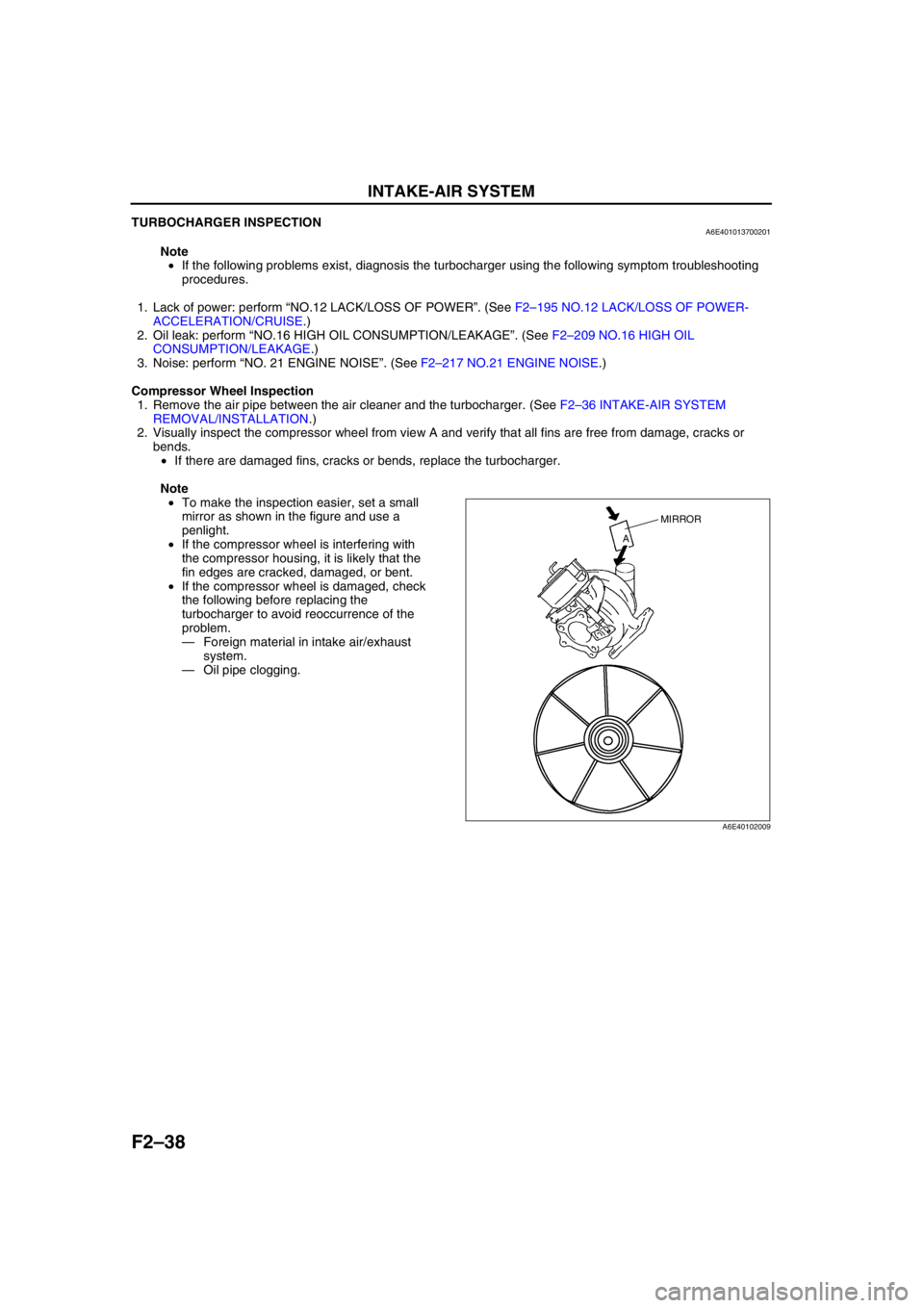
Compressor Wheel Inspection
1. Remove the air pipe between the air cleaner and the turbocharger. (See F2–36 INTAKE-AIR SYSTEM
REMOVAL/INSTALLATION.)
2. Visually inspect the compressor wheel from view A and verify that all fins are free from damage, cracks or
bends.
•If there are damaged fins, cracks or bends, replace the turbocharger.
Note
•To make the inspection easier, set a small
mirror as shown in the figure and use a
penlight.
•If the compressor wheel is interfering with
the compressor housing, it is likely that the
fin edges are cracked, damaged, or bent.
•If the compressor wheel is damaged, check
the following before replacing the
turbocharger to avoid reoccurrence of the
problem.
—Foreign material in intake air/exhaust
system.
—Oil pipe clogging.
MIRROR
A
A6E40102009
Page 201 of 909
FUEL SYSTEM
F2–49
F2
(2) Apply a slight amount of clean engine oil to
the sealing surface of the fuel pump unit.
(3) Align the fuel pipe on the fuel pump unit and
quick release connector so that the tabs of the
retainer are correctly fitted into the quick
release connector. Push the quick release
connector straight into the retainer until a click
is heard.
(4) Lightly pull and push the quick release
connector a few times by hand and verify that
it can move 2.0—3.0 mm {0.08—0.11 in} and
it is connected securely.
•If the quick release connector does not
move at all, verify that O-ring is not
damaged of that is has not slipped, and reconnect the quick release connector.
2. When the retainer is removed, perform the following procedure.
End Of Sie
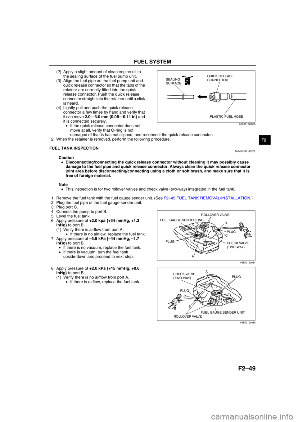
FUEL TANK INSPECTIONA6E401242110202
Caution
•Disconnecting/connecting the quick release connector without cleaning it may possibly cause
damage to the fuel pipe and quick release connector. Always clean the quick release connector
joint area before disconnecting/connecting using a cloth or soft brush, and make sure that it is
free of foreign material.
Note
•This inspection is for two rollover valves and check valve (two-way) integrated in the fuel tank.
1. Remove the fuel tank with the fuel gauge sender unit. (See F2–45 FUEL TANK REMOVAL/INSTALLATION.)
2. Plug the fuel pipe of the fuel gauge sender unit.
3. Plug port C.
4. Connect the pump to port B.
5. Level the fuel tank.
6. Apply pressure of +2.0 kpa {+34 mmHg, +1.3
inHg} to port B.
(1) Verify there is airflow from port A.
•If there is no airflow, replace the fuel tank.
7. Apply pressure of –5.9 kPa {–44 mmHg, –1.7
inHg} to port B.
•If there is no vacuum, replace the fuel tank.
•If there is vacuum, turn the fuel tank
upside-down and proceed to next step.
8. Apply pressure of +2.0 kPa {+15 mmHg, +0.6
inHg} to port B.
(1) Verify there is no airflow from port A.
•If there is airflow, replace the fuel tank.
End Of Sie
OILOIL
PLASTIC FUEL HOSE QUICK RELEASE
CONNECTOR SEALING
SURFACE
A6E3912W006
B
C
APLUG
PLUG
CHECK VALVE
(TWO-WAY)
FUEL GAUGE SENDER UNIT
ROLLOVER VALVE
A6E40122034
B CA
PLUGPLUG
CHECK VALVE
(TWO-WAY)
FUEL GAUGE SENDER UNIT
ROLLOVER VALVE
A6E40122035
Page 237 of 909
ON-BOARD DIAGNOSTIC
F2–85
F2
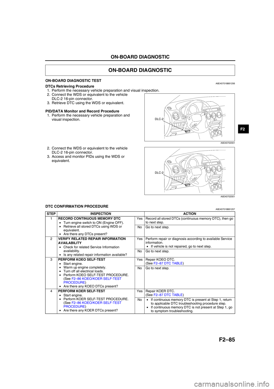
ON-BOARD DIAGNOSTIC TESTA6E407018881206DTCs Retrieving Procedure
1. Perform the necessary vehicle preparation and visual inspection.
2. Connect the WDS or equivalent to the vehicle
DLC-2 16-pin connector.
3. Retrieve DTC using the WDS or equivalent.
PID/DATA Monitor and Record Procedure
1. Perform the necessary vehicle preparation and
visual inspection.
2. Connect the WDS or equivalent to the vehicle
DLC-2 16-pin connector.
3. Access and monitor PIDs using the WDS or
equivalent.
End Of Sie
DTC CONFIRMATION PROCEDUREA6E407018881207
End Of Sie
ON-BOARD DIAGNOSTIC
DLC-2
A6E40702001
DLC-2
A6E40702001
STEP INSPECTION ACTION
1RECORD CONTINUOUS MEMORY DTC
•Turn engine switch to ON (Engine OFF).
•Retrieve all stored DTCs using WDS or
equivalent.
•Are there any DTCs present?Yes Record all stored DTCs (continuous memory DTC), then go
to next step.
No Go to next step.
2VERIFY RELATED REPAIR INFORMATION
AVAILABILITY
•Check for related Service Information
availability.
•Is any related repair information available?Yes Perform repair or diagnosis according to available Service
information.
•If vehicle is not repaired, go to next step.
No Go to next step.
3PERFORM KOEO SELF-TEST
•Start engine.
•Warm up engine completely.
•Turn off all electrical loads.
•Perform KOEO SELF-TEST PROCEDURE.
(See F2–86 KOEO/KOER SELF-TEST
PROCEDURE)
•Are there any KOEO DTCs present?Yes Repair KOEO DTC.
(See F2–87 DTC TABLE)
No Go to next step.
4PERFORM KOER SELF-TEST
•Start engine.
•Perform KOER SELF-TEST PROCEDURE.
(See F2–86 KOEO/KOER SELF-TEST
PROCEDURE)
•Are there any KOER DTCs present?Yes Repair KOER DTC.
(See F2–87 DTC TABLE)
No•If continuous memory DTC is present at Step 1, return
to applicable DTC troubleshooting procedure step.
•If continuous memory DTC is not present at Step 1, go
to symptom troubleshooting.
Page 240 of 909
F2–88
ON-BOARD DIAGNOSTIC
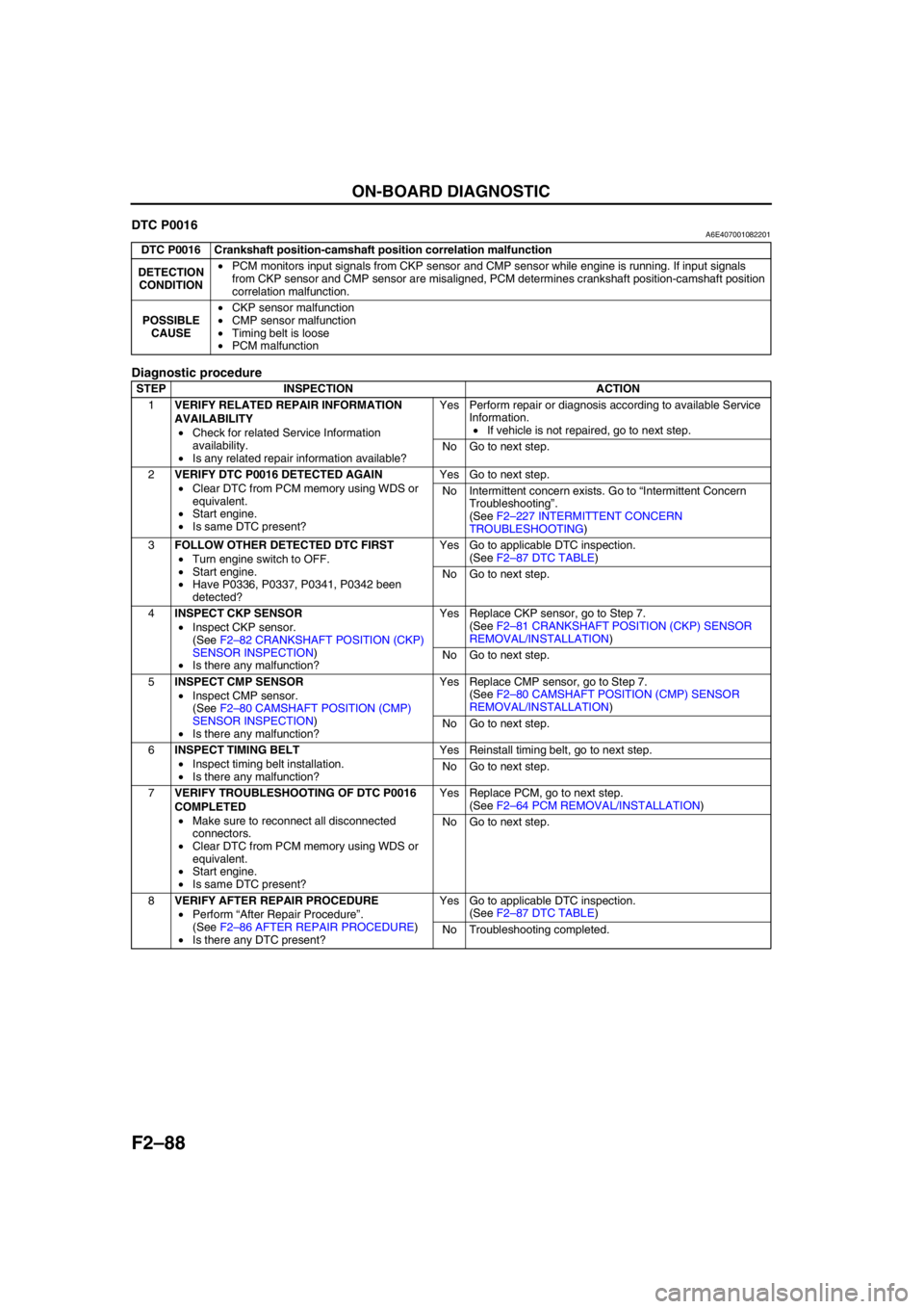
End Of SieDTC P0016A6E407001082201
Diagnostic procedure
End Of Sie
DTC P0016 Crankshaft position-camshaft position correlation malfunction
DETECTION
CONDITION•PCM monitors input signals from CKP sensor and CMP sensor while engine is running. If input signals
from CKP sensor and CMP sensor are misaligned, PCM determines crankshaft position-camshaft position
correlation malfunction.
POSSIBLE
CAUSE•CKP sensor malfunction
•CMP sensor malfunction
•Timing belt is loose
•PCM malfunction
STEP INSPECTION ACTION
1VERIFY RELATED REPAIR INFORMATION
AVAILABILITY
•Check for related Service Information
availability.
•Is any related repair information available?Yes Perform repair or diagnosis according to available Service
Information.
•If vehicle is not repaired, go to next step.
No Go to next step.
2VERIFY DTC P0016 DETECTED AGAIN
•Clear DTC from PCM memory using WDS or
equivalent.
•Start engine.
•Is same DTC present?Yes Go to next step.
No Intermittent concern exists. Go to “Intermittent Concern
Troubleshooting”.
(See F2–227 INTERMITTENT CONCERN
TROUBLESHOOTING)
3FOLLOW OTHER DETECTED DTC FIRST
•Turn engine switch to OFF.
•Start engine.
•Have P0336, P0337, P0341, P0342 been
detected?Yes Go to applicable DTC inspection.
(See F2–87 DTC TABLE)
No Go to next step.
4INSPECT CKP SENSOR
•Inspect CKP sensor.
(See F2–82 CRANKSHAFT POSITION (CKP)
SENSOR INSPECTION)
•Is there any malfunction?Yes Replace CKP sensor, go to Step 7.
(See F2–81 CRANKSHAFT POSITION (CKP) SENSOR
REMOVAL/INSTALLATION)
No Go to next step.
5INSPECT CMP SENSOR
•Inspect CMP sensor.
(See F2–80 CAMSHAFT POSITION (CMP)
SENSOR INSPECTION)
•Is there any malfunction?Yes Replace CMP sensor, go to Step 7.
(See F2–80 CAMSHAFT POSITION (CMP) SENSOR
REMOVAL/INSTALLATION)
No Go to next step.
6INSPECT TIMING BELT
•Inspect timing belt installation.
•Is there any malfunction?Yes Reinstall timing belt, go to next step.
No Go to next step.
7VERIFY TROUBLESHOOTING OF DTC P0016
COMPLETED
•Make sure to reconnect all disconnected
connectors.
•Clear DTC from PCM memory using WDS or
equivalent.
•Start engine.
•Is same DTC present?Yes Replace PCM, go to next step.
(See F2–64 PCM REMOVAL/INSTALLATION)
No Go to next step.
8VERIFY AFTER REPAIR PROCEDURE
•Perform “After Repair Procedure”.
(See F2–86 AFTER REPAIR PROCEDURE)
•Is there any DTC present?Yes Go to applicable DTC inspection.
(See F2–87 DTC TABLE)
No Troubleshooting completed.