turn signal MAZDA 6 2002 Suplement Repair Manual
[x] Cancel search | Manufacturer: MAZDA, Model Year: 2002, Model line: 6, Model: MAZDA 6 2002Pages: 909, PDF Size: 17.16 MB
Page 351 of 909

TROUBLESHOOTING
F2–199
F2
NO.13 KNOCKING/PINGINGA6E408018881215
Diagnostic Procedure
13 KNOCKING/PINGING
DESCRIPTION•Excessive shrilly knocking sound from engine.
POSSIBLE
CAUSE•Poor fuel quality
•Air leakage from intake-air system
•Intake-air system restriction or clogging
•Variable swirl control (VSC) system malfunction
•Variable boost control (VBC) system malfunction
•Intake shutter valve stuck close
•VSC valve stuck close
•Glow system malfunction
•Low engine compression
•Improper valve timing
•Low coolant temperature
•Incorrect fuel injection timing
•Erratic signal from CKP sensor
•Erratic signal from CMP sensor
•ECT sensor or related circuit malfunction
•MAF/IAT sensor or related circuit malfunction
•IAT sensor No.2 or related circuit malfunction
•Boost sensor or related malfunction
•Fuel pressure sensor or related circuit malfunction
•Accelerator position sensor or related circuit malfunction
•Excessive fuel pressure
•Fuel return line clogging or restriction
•EGR system malfunction
•Exhaust system and/or catalyst converter restriction
•Turbocharger malfunction
•Charge air cooler malfunction
•Suction control valve malfunction (built-in supply pump)
Warning
The following troubleshooting flow chart contains the fuel system diagnosis and repair
procedures. Read the following warnings before performing the fuel system services:
•Fuel vapor is hazardous. It can easily ignite, causing serious injury and damage. Always keep
sparks and flames away from fuel.
•Fuel line spills and leakage are dangerous. Fuel can ignite and cause serious injury or death
and damage. Fuel can also irritate skin and eyes. To prevent this, always complete “BEFORE
REPAIR PROCEDURE” and “AFTER REPAIR PROCEDURE” described in this manual.
STEP INSPECTION RESULTS ACTION
1 Does engine run cold? Yes Go to symptom troubleshooting “NO.18 COOLING
SYSTEM CONCERNS—RUNS COLD”.
No Go to next step.
2 Inspect for following:
•Fuel quality (e.g.: including water
contamination, winter/summer blend)
•Fuel return line clogging and/or restriction
•Intake-air system restriction or clogging
•Exhaust system and/or catalyst converter
restriction or clogging
•Charge air cooler condition (restriction or
damaged)
Are all items okay?Yes Go to next step.
No Service as necessary.
Repeat Step 2.
3 Connect WDS or equivalent to DLC-2.
Access ECT PID.
Verify ECT PID is above 80 °C {176 °F}?Yes Go to next step.
No Inspect ECT PID.
Page 365 of 909

TROUBLESHOOTING
F2–213
F2
NO.19 EXCESSIVE BLACK SMOKEA6E408018881221
Diagnostic Procedure
19 EXCESSIVE BLACK SMOKE
DESCRIPTION•Excessive black smoke is observed in exhaust gas.
POSSIBLE
CAUSE•Intake-air system clogging or restriction
•Air leakage from Intake-air system
•Incorrect fuel injection timing
•Erratic signal from CKP sensor
•Fuel pressure sensor or related circuit malfunction
•Boost sensor or related circuit malfunction
•IAT sensor No.2 or related circuit malfunction
•Fuel injector malfunction
•Excessive fuel pressure
•Suction control valve malfunction (built-in supply pump)
•Fuel line clogging or restriction
•Fuel pressure limiter malfunction (built-in common rail)
•Low engine compression
•Improper valve timing
•Base engine malfunction
•EGR system malfunction
•Variable boost control (VBC) system malfunction
•Vacuum leakage
•Turbocharger malfunction
•Charge air cooler malfunction
•Intake shutter valve malfunction
•Variable swirl control (VSC) system malfunction
•VSC valve malfunction
•IDM or related circuit malfunction
•Exhaust system and/or catalyst converter restriction or clogging
Warning
The following troubleshooting flow chart contains the fuel system diagnosis and repair
procedures. Read the following warnings before performing the fuel system services:
•Fuel vapor is hazardous. It can easily ignite, causing serious injury and damage. Always keep
sparks and flames away from fuel.
•Fuel line spills and leakage are dangerous. Fuel can ignite and cause serious injury or death
and damage. Fuel can also irritate skin and eyes. To prevent this, always complete “BEFORE
REPAIR PROCEDURE” and “AFTER REPAIR PROCEDURE” described in this manual.
STEP INSPECTION RESULTS ACTION
1 Inspect for following:
•Intake-air system clogging or restriction
•Exhaust system and/or catalyst converter
restriction or clogging
•Charge air cooler condition (restriction or
damaged)
Are all items okay?Yes Go to next step.
No Service as necessary.
Repeat Step 1.
2 Perform self-test function using WDS or
equivalent.
Turn engine switch to ON.
Retrieve any DTC.
Is DTC displayed?YesDTC is displayed:
Go to appropriate DTC test.
Communication error message is displayed:
Inspect for following:
•Open circuit between PCM control relay and PCM
terminal 53 or 79
•Open circuit PCM control relay and PCM terminal
69
•PCM control relay stuck open
•Open or poor GND circuit (PCM terminal 65, 85,
103 or 104)
•Poor connection vehicle body GND
NoNo DTC is displayed:
Go to next step.
3 Does any other symptom exist? Yes Go to appropriate flowchart.
No Go to next step.
4 Inspect for air cleaner element for clogging.
Is air cleaner element okay?Yes Go to next step.
No Repair or replace air cleaner element.
Page 427 of 909

K2–12
AUTOMATIC TRANSAXLE
Electronic Control Item and Control
Component Description (Electronic Control)
Control item Contents
Shift control•Detects engine load condition and vehicle speed. Shifts to the best gear
position according to the programmed automatic shift diagram.
Line pressure control•Generates line pressure matching the engine load condition and driving
conditions. Optimizes line pressure for each shift. When the ATF
temperature is low, automatically optimizes line pressure for quick clutch
engagement.
Revers inhibition control•When the shift lever is shifted to R position while the vehicle is running
forward at approx. 30 km/h{19 mph} or more, the TCM turns the neutral
shift solenoid valve on and drains the low and reverse brake hydraulic
pressure. Due to this, the transaxle shifts to neutral.
Shift transient control•Adjusts transient hydraulic pressure according to engine load and
vehicle driving conditions when shifting using the pressure control
solenoid, 2-4 brake solenoid valve, the high clutch solenoid valve, and
each accumulator control valve.
•Temporarily lowers engine torque during shift (up and down) to improve
shift feel
•The lock timing for the reduction brake band is controlled by the control
of the reduction timing solenoid valve ON/OFF timing.
•The lock timing for the clutch brake is controlled by the control of shift
solenoid A, B, and C ON/OFF timing.
Feedback control•Corrects clutch engagement pressure and timing on drain side to
compensate for changes in engine performance and changes in
transaxle
TCC control•Controls TCC according to the programmed TCC points
N-D select control•When a driving range is selected from P/N, the fuel injection amount is
controlled to prevent fluctuation in engine speed.
Slope mode control•Changes the shift point to prevent frequent shifting up/down when
climbing hills
OBD system•Detects and/or memorizes failure of input/output part and transaxle
condition
Part name Function
Input system TR switch•Detects selector lever ranges/positions
Input/turbine speed sensor•Detects reverse clutch drum revolution speed
Intermediate sensor•Detects output gear revolution speed
Vehicle speedometer sensor•Detects parking gear revolution speed
TFT sensor•Detects the ATF temperature
Brake switch•Detects the brake pedal depressed
Cruise control module (in cruise actuator)•When the cruise control is in use, the signal detects when the
difference between the target speed and actual speed
exceeds specification
M range switch•Detects selector lever shifted M range
Up switch•Detects up shift in M range
Down switch•Detects down shift in M range
CAN signal Throttle position signal•Input throttle opening angle from PCM
Engine torque signal
(without torque down)•Input engine torque from PCM
Engine torque signal (with
torque down)•Input engine torque from PCM
Engine torque signal (loss
torque)•Input engine loss torque from PCM
Torque reduced signal•Detects signals indicating torque down availability
Engine coolant
temperature signal•Input engine coolant temperature from PCM
Engine speed signal•Input engine speed from PCM
Battery OFF signal•Detect negative battery cable disconnected
4 wheel speed signal•Input wheel speed from ABS HU/CM or DSC HU/CM
Page 468 of 909

AUTOMATIC TRANSAXLE
K2–53
K2
Operation
Manual mode shift
•When the selector lever is shifted over from the D to M range position, the M range switch in the selector lever
component turns on, sending a manual mode command signal to the PCM which activates the manual mode
shift control.
•When in manual mode and the selector lever is operated in the back (+) direction, the up switch in the selector
lever component is turned on and an up-shift command signal is inputted to the PCM.
—The PCM, triggered by the up-shift command signal, carries out shifting by outputting an operation signal to
the shift solenoid if the ATF temperature is not low (for 3GR only), vehicle speed is higher than the set
speed and the gear position is 3GR or lower.
•Conversely, when the selector lever is operated in the forward (-) direction, the down switch in the selector lever
component turns on, and a down-shift command signal is inputted to the PCM.
—The PCM, triggered by the down-shift command signal, carries out shifting by outputting an operation
signal to the shift solenoid if the vehicle speed is less than the set speed and the gear position is 2GR or
above.
•The PCM utilizes a specialized M range automatic shift diagram when down shifting. This restriction of manual
downshifting is carried out to reduce load on the ATX and prevent engine over-revving.
13 Instrument cluster
14 Input15 Selector lever component
-M range switch
-Up switch
-Down switch
16 TR switch
17 ABS HU/CM or DSC HU/CM
18 TFT sensor
Condition Shift control Note
2GR→3GR up-shift command
at low speed•To reduce load on the ATX, upshifting is
inhibited until vehicle reaches speed
possible for upshifting
— 3GR→4GR up-shift command
at low speed
3GR→4GR up-shift command,
low ATF temperature•To reduce load on the ATX, upshifting to
4GR is inhibited
4GR→3GR down-shift
command, above set speed•To prevent engine over-rev, downshifting is
inhibited until vehicle reaches speed
possible for downshifting•Selector indicator “M” light and gear
position indicator light flash to alert
driver
3GR→2GR down-shift
command, above set speed
2GR→1GR down-shift
command, above set speed
In 4GR deceleration, speed
goes below coast-down set
speed (deceleration down-
shift)•To assure drive stability, automatically
downshifts from 4GR to 3GR
— In 3GR deceleration, speed
goes below coast-down set
speed (deceleration down-
shift)•To assure drive stability, automatically
downshifts from 3GR to 1GR
In 2GR deceleration, speed
goes below coast-down set
speed (deceleration down-
shift)•To assure driving stability, automatically
downshifts from 2GR to 1GR
Page 474 of 909

AUTOMATIC TRANSAXLE
K2–59
K2
Operation
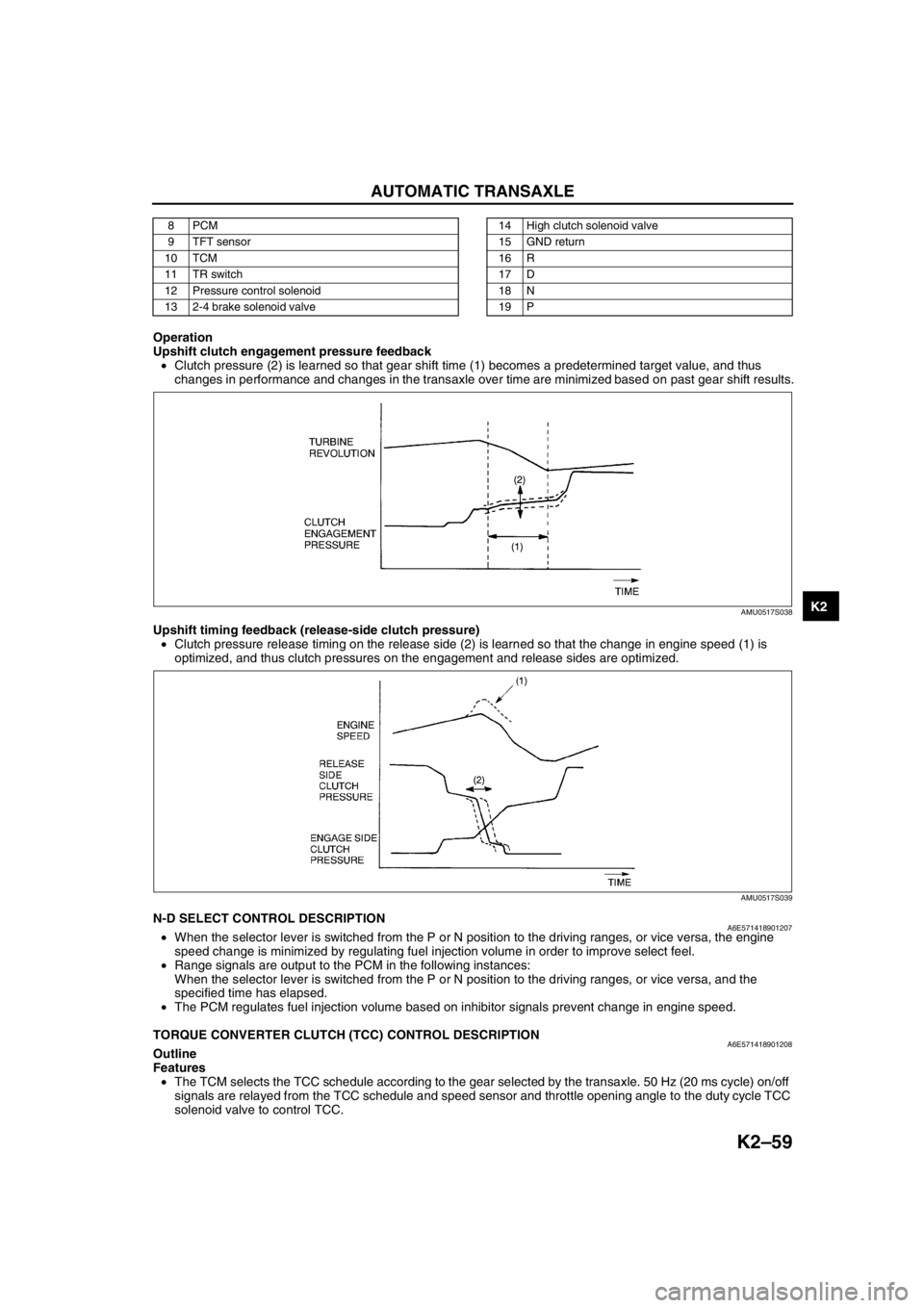
Upshift clutch engagement pressure feedback
•Clutch pressure (2) is learned so that gear shift time (1) becomes a predetermined target value, and thus
changes in performance and changes in the transaxle over time are minimized based on past gear shift results.
Upshift timing feedback (release-side clutch pressure)
•Clutch pressure release timing on the release side (2) is learned so that the change in engine speed (1) is
optimized, and thus clutch pressures on the engagement and release sides are optimized.
End Of SieN-D SELECT CONTROL DESCRIPTIONA6E571418901207•When the selector lever is switched from the P or N position to the driving ranges, or vice versa, the engine
speed change is minimized by regulating fuel injection volume in order to improve select feel.
•Range signals are output to the PCM in the following instances:
When the selector lever is switched from the P or N position to the driving ranges, or vice versa, and the
specified time has elapsed.
•The PCM regulates fuel injection volume based on inhibitor signals prevent change in engine speed.
End Of Sie
TORQUE CONVERTER CLUTCH (TCC) CONTROL DESCRIPTIONA6E571418901208Outline
Features
•The TCM selects the TCC schedule according to the gear selected by the transaxle. 50 Hz (20 ms cycle) on/off
signals are relayed from the TCC schedule and speed sensor and throttle opening angle to the duty cycle TCC
solenoid valve to control TCC.
8PCM
9 TFT sensor
10 TCM
11 TR switch
12 Pressure control solenoid
13 2-4 brake solenoid valve14 High clutch solenoid valve
15 GND return
16 R
17 D
18 N
19 P
AMU0517S038
AMU0517S039
Page 480 of 909

AUTOMATIC TRANSAXLE
K2–65
K2
Memory Function
•The memory function stores failure information detected in the failure detection function. Once failure
information is stored, the memory will not be cleared even when the ignition switch is turned off (LOCK
position) or the malfunction is repaired.
•The stored memory (failure information) can be cleared by using the WDS or disconnecting the negative
battery cable.
Failure Indication Function
•The failure indication function illuminates the AT warning lights when the failure detection function determines
there is a malfunction.
DTC Table
X : Available
CCM:Continuous monitor
Fail-safe Function
•In the fail-safe function, minimum vehicle drivability is obtained by changing the signals that are determined as
malfunctions by the failure detection function to the preset values, and limiting the TCM control.
DTC No. On-board diagnostic function MILAT warning
light
indicationDCMonitor
itemMemory
function
P0705 TR switch circuit malfunction (Power short circuit) X X 2 CCM X
P0706 TR switch circuit malfunction (Open/ground short circuit) X X 2 CCM X
P0711 TFT sensor malfunction (Stuck) X–2 CCM X
P0712 TFT sensor circuit malfunction (Short circuit) X X 2 CCM X
P0713 TFT sensor circuit malfunction (Open circuit) X X 2 CCM X
P0715 Input/turbine speed sensor circuit malfunction X X 2 CCM X
P0720 Vehicle speedometer sensor circuit malfunction X X 2 CCM X
P0740 TCC system X–2 CCM X
P0743 TCC solenoid valve malfunction (Open/short) X X 1 CCM X
P0748 Pressure control solenoid malfunction (Open/short)–X–CCM X
P0751 Shift solenoid A malfunction (Stuck off) X–2 CCM X
P0752 Shift solenoid A malfunction (Stuck on) X–2 CCM X
P0753 Shift solenoid A malfunction (Open/short) X X 1 CCM X
P0756 Shift solenoid B malfunction (Stuck off) X–2 CCM X
P0757 Shift solenoid B malfunction (Stuck on) X–2 CCM X
P0758 Shift solenoid B malfunction (Open/short) X X 1 CCM X
P0761 Shift solenoid C malfunction (Stuck off) X–2 CCM X
P0762 Shift solenoid C malfunction (Stuck on) X–2 CCM X
P0763 Shift solenoid C malfunction (Open/short) X X 1 CCM X
P0768 Reduction timing solenoid malfunction (Open/short)–X–CCM X
P0773 Neutral shift solenoid malfunction (Open/short)–X–CCM X
P0778 2-4 brake solenoid malfunction (Open/short)–X–CCM X
P0791 Intermediate sensor malfunction (Open/short) X X 2 CCM X
P0798 High clutch solenoid malfunction (Open/short)–X–CCM X
P1710 GND return malfunction–––Other X
U0073 CAN BUS OFF X X 1 CCM X
U0100 TCM cannot receive any signals from PCM X X 1 CCM X
DTC
No.On-board diagnostic function Detection condition Fail-safe TCC
P0705Transaxle range (TR) switch
circuit malfunction (power short
circuit)•Two or more range signals
are inputted from TR switch
for 5 seconds or more•TR switch priority
D > N > P > R
•Inhibits feedback control,
SLOPE mode, torque
reduction controlAvailable
P0706Transaxle range (TR) switch
circuit malfunction (open/ground
short circuit)•No range signal is inputted
from TR switch for 100
seconds or more•Inhibits feedback control,
SLOPE mode, torque
reduction controlAvailable
Page 482 of 909

AUTOMATIC TRANSAXLE
K2–67
K2
P0758Shift solenoid B malfunction
(open/short)•Open or short in shift
solenoid B circuit (Voltage
different from on/off signal
relayed by CPU in TCM is
detected while TCM is
monitoring solenoid output
voltage.)•Stops driving all ON/OFF
type solenoids (OFF) and
TCC solenoid valve (OFF)Inhibition
P0761Shift solenoid C malfunction
(stuck off)•Difference between actual
gear ratio and gear ratio set
in TCM is large—Available
P0762Shift solenoid C malfunction
(stuck on)•Difference between actual
gear ratio and gear ratio set
in TCM is large—Available
P0763Shift solenoid C malfunction
(open/short)•Open or short in shift
solenoid C circuit (Voltage
different from on/off signal
relayed by CPU in TCM is
detected while TCM is
monitoring solenoid output
voltage.)•Stops driving all ON/OFF
type solenoids (OFF) and
TCC solenoid valve (OFF)Inhibition
P0768Reduction timing solenoid valve
malfunction (open/short)•Open or short in reduction
timing solenoid valve circuit
(Voltage different from on/off
signal relayed by CPU in
TCM is detected while TCM
is monitoring solenoid
output voltage.)•Stops driving of reduction
timing solenoid valve (OFF)Available
P0773Neutral shift solenoid valve
malfunction (open/short)•Open or short in neutral shift
solenoid valve circuit
(Voltage different from on/off
signal relayed by CPU in
TCM is detected while TCM
is monitoring solenoid
output voltage.)•Stops driving of neutral shift
solenoid valve (OFF)Available
P07782-4 brake solenoid valve
malfunction (open/short)•Open or short in 2-4 brake
solenoid valve circuit
(Voltage different from on/off
signal relayed by CPU in
TCM is detected while TCM
is monitoring solenoid
output voltage.)•Stops driving of pressure
control solenoid, 2-4 brake
solenoid valve, and high
clutch solenoid valve (OFF)
•Inhibit feedback control.Available
P0791Intermediate sensor malfunction
(open/short)•Rotation speed of output
gear (intermediate sensor)
is low when vehicle speed
and engine speed exceed
the pre programmed value•Inhibit feedback control
•Inhibits torque reduction
controlAvailable
P0798High clutch solenoid valve
malfunction (open/short)•Open or short in high clutch
solenoid valve circuit
(Voltage different from on/off
signal relayed by CPU in
TCM is detected while TCM
is monitoring solenoid
output voltage.)•Stops driving of pressure
control solenoid, 2-4 brake
solenoid valve, and high
clutch solenoid valve (OFF)
•Inhibit feedback control.Available
P1710 GND return malfunction•TCM detects open in GND
return signal of solenoid.—Available
U0073 CAN BUS OFF•CAN controller damaged.•Throttle valve opening angle
is fixed (4/8) at the time in
order to determine shift
•Maximizes line pressureInhibition
U0100TCM cannot receive any signals
from PCM•TCM cannot receive any
signals from PCM DTC
No.On-board diagnostic function Detection condition Fail-safe TCC
Page 495 of 909

K2–80
AUTOMATIC TRANSAXLE
AUTOMATIC TRANSAXLE FLUID (ATF) REPLACEMENTA6E571419001202
Warning
•When the transaxle and ATF are hot, they can badly burn you. Turn off the engine and wait until
they are cool before changing the ATF.
1. Remove the oil dipstick.
2. Remove the oil drain plug and washer.
3. Drain the ATF into a container.
4. Install a new washer and the drain plug.
Tightening torque
39—54 N·m {3.9—5.6 kgf·m, 29—40 ft·lbf}
5. Add the specified type of ATF through the oil filler
tube, until ATF level reaches lower notch of
dipstick.
ATF type
ATF M-III or equivalent (e.g. Dexron
®III)
Capacity (Approximate quantity)
8.3 L {8.8 US qt, 7.3 Imp qt}
6. Verify that the ATF level is in the HOT (65 °C {149 °F}) range.
•Add ATF to the specified level as necessary.
End Of Sie
TRANSAXLE RANGE (TR) SWITCH INSPECTIONA6E571419440201
Note
•Input signals of the TR switch can be inspected with a WDS or equivalent. (See K2–90 TCM
INSPECTION.)
Inspection of Operation
1. Verify that the starter operates only with the ignition switch at the START position and the selector lever in P
and N positions.
•If not as specified, inspect for continuity at the TR switch. (See K2–80 Inspection of Continuity.)
2. Verify that the back-up lights illuminate when shifted to R position with the ignition switch at the ON position.
•If not as specified, inspect for continuity at the TR switch.
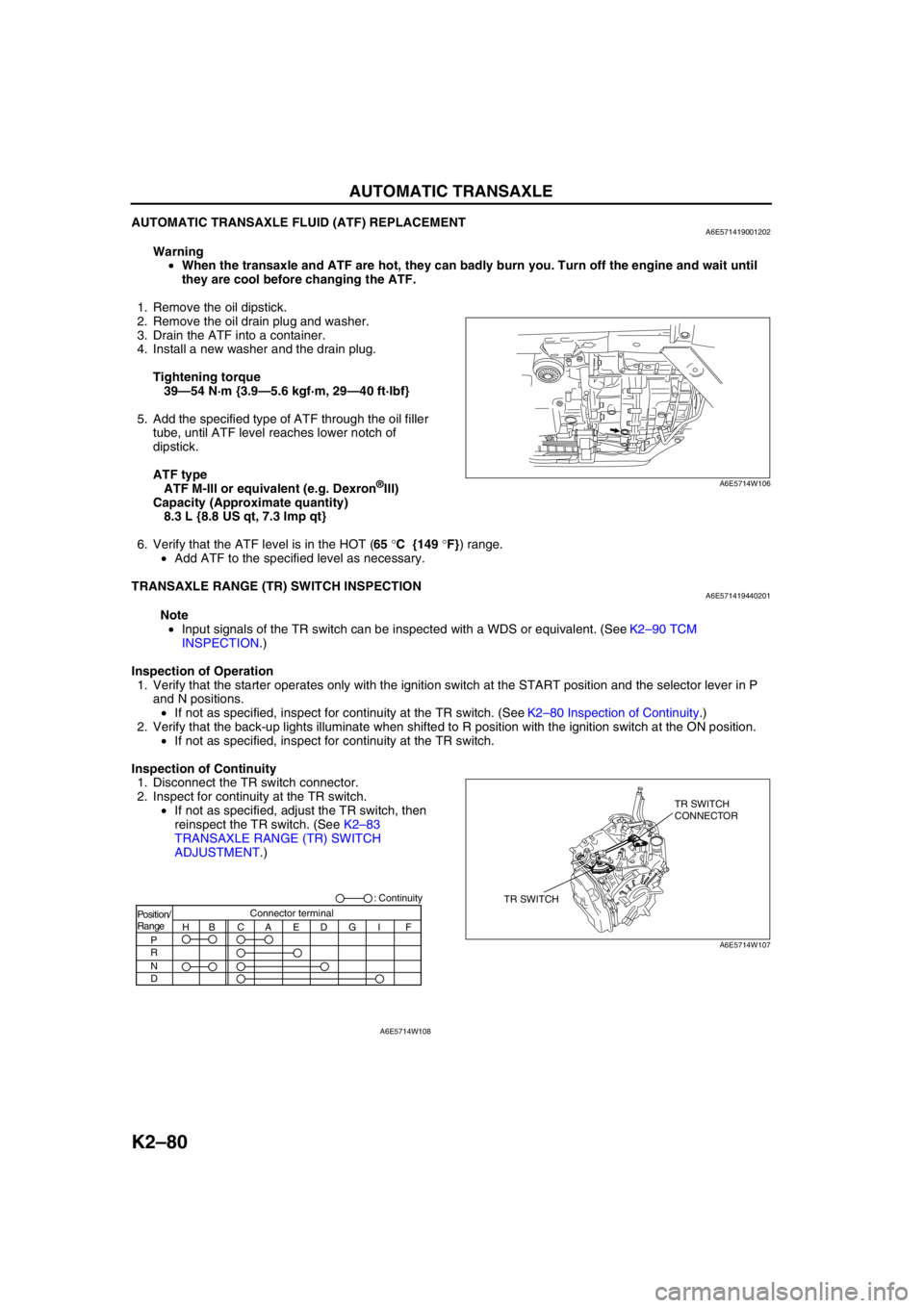
Inspection of Continuity
1. Disconnect the TR switch connector.
2. Inspect for continuity at the TR switch.
•If not as specified, adjust the TR switch, then
reinspect the TR switch. (See K2–83
TRANSAXLE RANGE (TR) SWITCH
ADJUSTMENT.)
A6E5714W106
TR SWITCHTR SWITCH
CONNECTOR
A6E5714W107
Position/
Range
H
P
R
N
DBCAEDGI FConnector terminal: Continuity
A6E5714W108
Page 508 of 909

AUTOMATIC TRANSAXLE
K2–93
K2
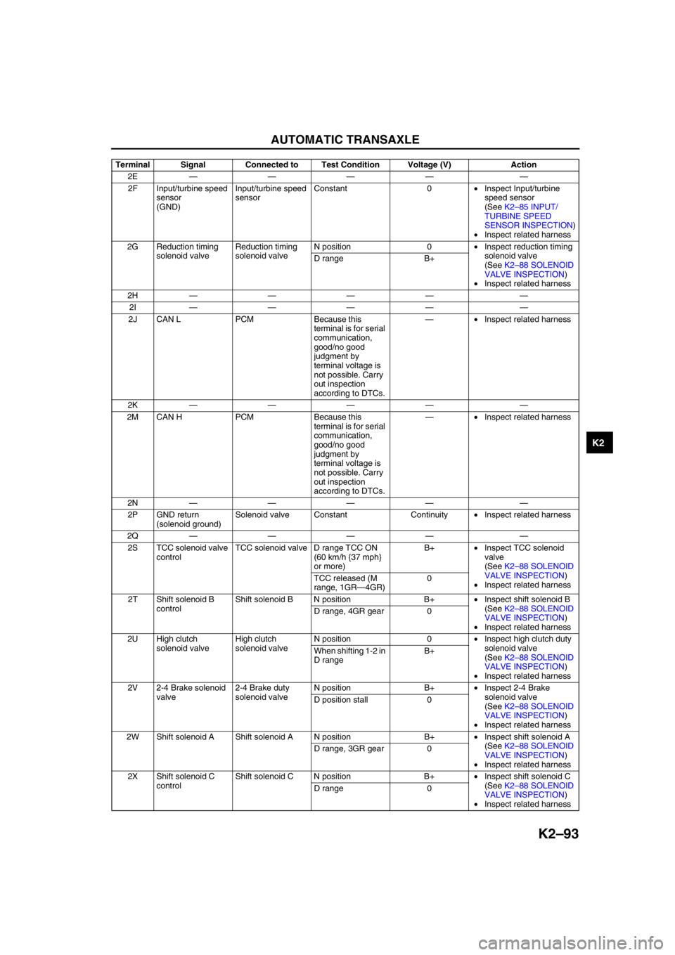
2E———— —
2F Input/turbine speed
sensor
(GND)Input/turbine speed
sensorConstant 0•Inspect Input/turbine
speed sensor
(See K2–85 INPUT/
TURBINE SPEED
SENSOR INSPECTION)
•Inspect related harness
2G Reduction timing
solenoid valveReduction timing
solenoid valveN position 0•Inspect reduction timing
solenoid valve
(See K2–88 SOLENOID
VALVE INSPECTION)
•Inspect related harness D range B+
2H———— —
2I———— —
2J CAN L PCM Because this
terminal is for serial
communication,
good/no good
judgment by
terminal voltage is
not possible. Carry
out inspection
according to DTCs.—•Inspect related harness
2K———— —
2M CAN H PCM Because this
terminal is for serial
communication,
good/no good
judgment by
terminal voltage is
not possible. Carry
out inspection
according to DTCs.—•Inspect related harness
2N———— —
2P GND return
(solenoid ground)Solenoid valve Constant Continuity•Inspect related harness
2Q———— —
2S TCC solenoid valve
controlTCC solenoid valve D range TCC ON
(60 km/h {37 mph}
or more)B+•Inspect TCC solenoid
valve
(See K2–88 SOLENOID
VALVE INSPECTION)
•Inspect related harness TCC released (M
range, 1GR—4GR)0
2T Shift solenoid B
controlShift solenoid B N position B+•Inspect shift solenoid B
(See K2–88 SOLENOID
VALVE INSPECTION)
•Inspect related harness D range, 4GR gear 0
2U High clutch
solenoid valveHigh clutch
solenoid valveN position 0•Inspect high clutch duty
solenoid valve
(See K2–88 SOLENOID
VALVE INSPECTION)
•Inspect related harness When shifting 1-2 in
D rangeB+
2V 2-4 Brake solenoid
valve2-4 Brake duty
solenoid valveN position B+•Inspect 2-4 Brake
solenoid valve
(See K2–88 SOLENOID
VALVE INSPECTION)
•Inspect related harness D position stall 0
2W Shift solenoid A Shift solenoid A N position B+•Inspect shift solenoid A
(See K2–88 SOLENOID
VALVE INSPECTION)
•Inspect related harness D range, 3GR gear 0
2X Shift solenoid C
controlShift solenoid C N position B+•Inspect shift solenoid C
(See K2–88 SOLENOID
VALVE INSPECTION)
•Inspect related harness D range 0 Terminal Signal Connected to Test Condition Voltage (V) Action
Page 541 of 909

K2–126
ON-BOARD DIAGNOSTIC
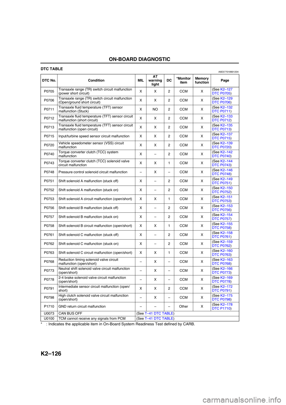
DTC TABLEA6E577018901204
* : Indicates the applicable item in On-Board System Readiness Test defined by CARB.
End Of Sie
DTC No. Condition MILAT
warning
lightDC*Monitor
itemMemory
functionPage
P0705Transaxle range (TR) switch circuit malfunction
(power short circuit)XX2CCM X(See K2–127
DTC P0705)
P0706Transaxle range (TR) switch circuit malfunction
(Open/ground short circuit)XX2CCM X(See K2–129
DTC P0706)
P0711Transaxle fluid temperature (TFT) sensor
malfunction (Stuck)XNO2CCM X(See K2–132
DTC P0711)
P0712Transaxle fluid temperature (TFT) sensor circuit
malfunction (short circuit)XX2CCM X(See K2–133
DTC P0712)
P0713Transaxle fluid temperature (TFT) sensor circuit
malfunction (open circuit)XX2CCM X(See K2–135
DTC P0713)
P0715 Input/turbine speed sensor circuit malfunction X X 2 CCM X(See K2–137
DTC P0715)
P0720Vehicle speedometer sensor (VSS) circuit
malfunctionXX2CCM X(See K2–139
DTC P0720)
P0740Torque converter clutch (TCC) system
malfunctionX–2CCM X(See K2–142
DTC P0740)
P0743Torque converter clutch (TCC) solenoid valve
circuit malfunctionXX1CCM X(See K2–144
DTC P0743)
P0748 Pressure control solenoid circuit malfunction–X–CCM X(See K2–146
DTC P0748)
P0751 Shift solenoid A malfunction (stuck off) X–2CCM X(See K2–149
DTC P0751)
P0752 Shift solenoid A malfunction (stuck on) X–2CCM X(See K2–150
DTC P0752)
P0753 Shift solenoid A circuit malfunction (open/short) X X 1 CCM X(See K2–151
DTC P0753)
P0756 Shift solenoid B malfunction (stuck off) X–2CCM X(See K2–153
DTC P0756)
P0757 Shift solenoid B malfunction (stuck on) X–2CCM X(See K2–154
DTC P0757)
P0758 Shift solenoid B circuit malfunction (open/short) X X 1 CCM X(See K2–155
DTC P0758)
P0761 Shift solenoid C malfunction (stuck off) X–2CCM X(See K2–158
DTC P0761)
P0762 Shift solenoid C malfunction (stuck on) X–2CCM X(See K2–159
DTC P0762)
P0763 Shift solenoid C circuit malfunction (open/short) X X 1 CCM X(See K2–160
DTC P0763)
P0768Reduction timing solenoid valve circuit
malfunction (open/short)–X–CCM X(See K2–163
DTC P0768)
P0773Neutral shift solenoid valve circuit malfunction
(open/short)–X–CCM X(See K2–166
DTC P0773)
P07782-4 brake solenoid valve circuit malfunction
(open/short)–X–CCM X(See K2–169
DTC P0778)
P0791Intermediate sensor circuit malfunction (open/
short)XX2CCM X(See K2–172
DTC P0791)
P0798High clutch solenoid valve circuit malfunction
(open/short)–X–CCM X(See K2–175
DTC P0798)
P1710 GND return circuit malfunction–––Other X(See K2–178
DTC P1710)
U0073 CAN BUS OFF (See T–41 DTC TABLE)
U0100 TCM cannot receive any signals from PCM (See T–41 DTC TABLE)