air condition MAZDA 6 2002 Suplement Manual PDF
[x] Cancel search | Manufacturer: MAZDA, Model Year: 2002, Model line: 6, Model: MAZDA 6 2002Pages: 909, PDF Size: 17.16 MB
Page 304 of 909

F2–152
ON-BOARD DIAGNOSTIC
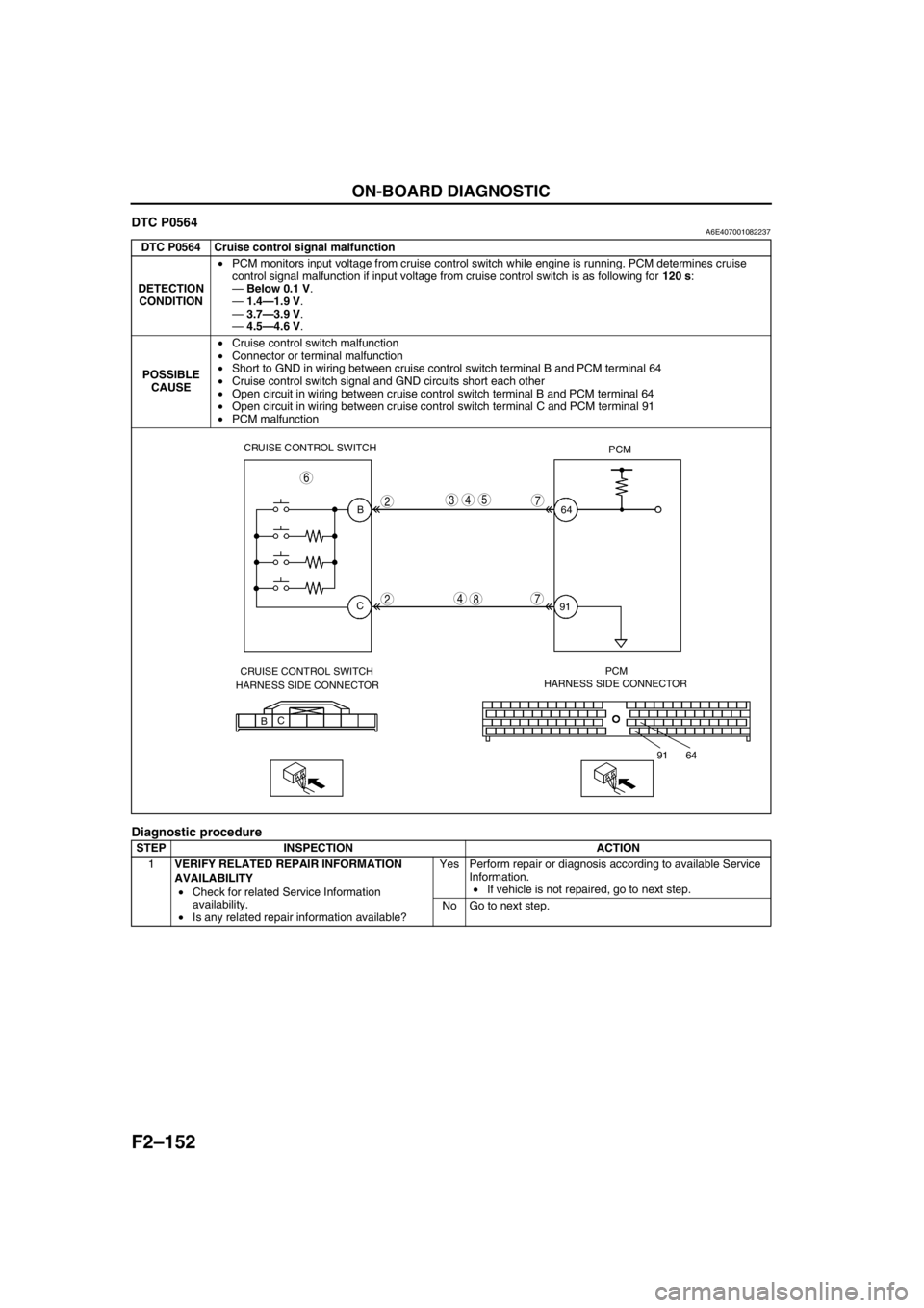
DTC P0564A6E407001082237
Diagnostic procedure
DTC P0564 Cruise control signal malfunction
DETECTION
CONDITION•PCM monitors input voltage from cruise control switch while engine is running. PCM determines cruise
control signal malfunction if input voltage from cruise control switch is as following for 120 s:
—Below 0.1 V.
—1.4—1.9 V.
—3.7—3.9 V.
—4.5—4.6 V.
POSSIBLE
CAUSE•Cruise control switch malfunction
•Connector or terminal malfunction
•Short to GND in wiring between cruise control switch terminal B and PCM terminal 64
•Cruise control switch signal and GND circuits short each other
•Open circuit in wiring between cruise control switch terminal B and PCM terminal 64
•Open circuit in wiring between cruise control switch terminal C and PCM terminal 91
•PCM malfunction
STEP INSPECTION ACTION
1VERIFY RELATED REPAIR INFORMATION
AVAILABILITY
•Check for related Service Information
availability.
•Is any related repair information available?Yes Perform repair or diagnosis according to available Service
Information.
•If vehicle is not repaired, go to next step.
No Go to next step.
CRUISE CONTROL SWITCH
PCM
B
C64
91
CRUISE CONTROL SWITCH
HARNESS SIDE CONNECTORPCM
HARNESS SIDE CONNECTOR
BC
64 91
2
2
543
4
7
6
78
Page 306 of 909

F2–154
ON-BOARD DIAGNOSTIC
DTC P0602A6E407001082238
Diagnostic procedure
End Of Sie
DTC P0602 PCM programming error
DETECTION
CONDITION•No configuration data in PCM
Note
•If “PCM CONFIGURATION” is successful, the PCM stored DTC P0602 and illuminates the MIL
(System i s normal). Clear the DTC P0602 using WDS or equivalent after “PCM CONFIGURATION”.
•MIL goes off after three drive cycles with no failure (DTCs remain in PCM).
POSSIBLE
CAUSE•Complete configuration has not been completed.
•PCM malfunction
STEP INSPECTION ACTION
1PERFORM DTC CONFIRMATION PROCEDURE
•Perform “DTC Confirmation Procedure”.
(See F2–85 DTC CONFIRMATION
PROCEDURE)
•Is same DTC present during KOEO or KOER
self-test?Yes Perform “PCM Configuration Procedure”, then go to next
step.
(See F2–68 PCM CONFIGURATION)
No Intermittent concern exists. Go to “Intermittent Concern
Troubleshooting”.
(See F2–227 INTERMITTENT CONCERN
TROUBLESHOOTING)
2VERIFY TROUBLESHOOTING OF DTC P0602
COMPLETED
•Make sure to reconnect all disconnected
connectors.
•Clear DTC from PCM memory using WDS or
equivalent.
•Perform KOEO/KOER self-test.
(See F2–86 KOEO/KOER SELF-TEST
PROCEDURE)
•Is same DTC present?Yes Replace PCM, go to next step.
(See F2–64 PCM REMOVAL/INSTALLATION)
No Go to next step.
3VERIFY AFTER REPAIR PROCEDURE
•Perform “After Repair Procedure”.
(See F2–86 AFTER REPAIR PROCEDURE)
•Is there any DTC present?Yes Go to applicable DTC inspection.
(See F2–87 DTC TABLE)
No Troubleshooting completed.
Page 307 of 909

ON-BOARD DIAGNOSTIC
F2–155
F2
DTC P0606A6E407001082239
Diagnostic procedure
End Of Sie
DTC P0610A6E407001082240
Diagnostic procedure
End Of Sie
DTC P0606 PCM malfunction
DETECTION
CONDITION•PCM does not read DTC from output devices.
POSSIBLE
CAUSE•PCM internal malfunction
STEP INSPECTION ACTION
1
––Replace PCM.
(See F2–64 PCM REMOVAL/INSTALLATION)
DTC P0610 Control module vehicle options error
DETECTION
CONDITION•PCM data configuration error
POSSIBLE
CAUSE•Configuration procedure has not been completed
•PCM malfunction
STEP INSPECTION ACTION
1PERFORM DTC CONFIRMATION PROCEDURE
•Perform “DTC Confirmation Procedure”.
(See F2–85 DTC CONFIRMATION
PROCEDURE)
•Is same DTC present during KOEO or KOER
self-test?Yes Perform “PCM Configuration Procedure”, then go to next
step.
(See F2–68 PCM CONFIGURATION)
No Intermittent concern exists. Go to “Intermittent Concern
Troubleshooting”.
(See F2–227 INTERMITTENT CONCERN
TROUBLESHOOTING)
2VERIFY TROUBLESHOOTING OF DTC P0610
COMPLETED
•Make sure to reconnect all disconnected
connectors.
•Clear DTC from PCM memory using WDS or
equivalent.
•Perform KOEO/KOER self-test.
(See F2–86 KOEO/KOER SELF-TEST
PROCEDURE)
•Is same DTC present?Yes Replace PCM, go to next step.
(See F2–64 PCM REMOVAL/INSTALLATION)
No Go to next step.
3VERIFY AFTER REPAIR PROCEDURE
•Perform “After Repair Procedure”.
(See F2–86 AFTER REPAIR PROCEDURE)
•Is there any DTC present?Yes Go to applicable DTC inspection.
(See F2–87 DTC TABLE)
No Troubleshooting completed.
Page 312 of 909

F2–160
ON-BOARD DIAGNOSTIC
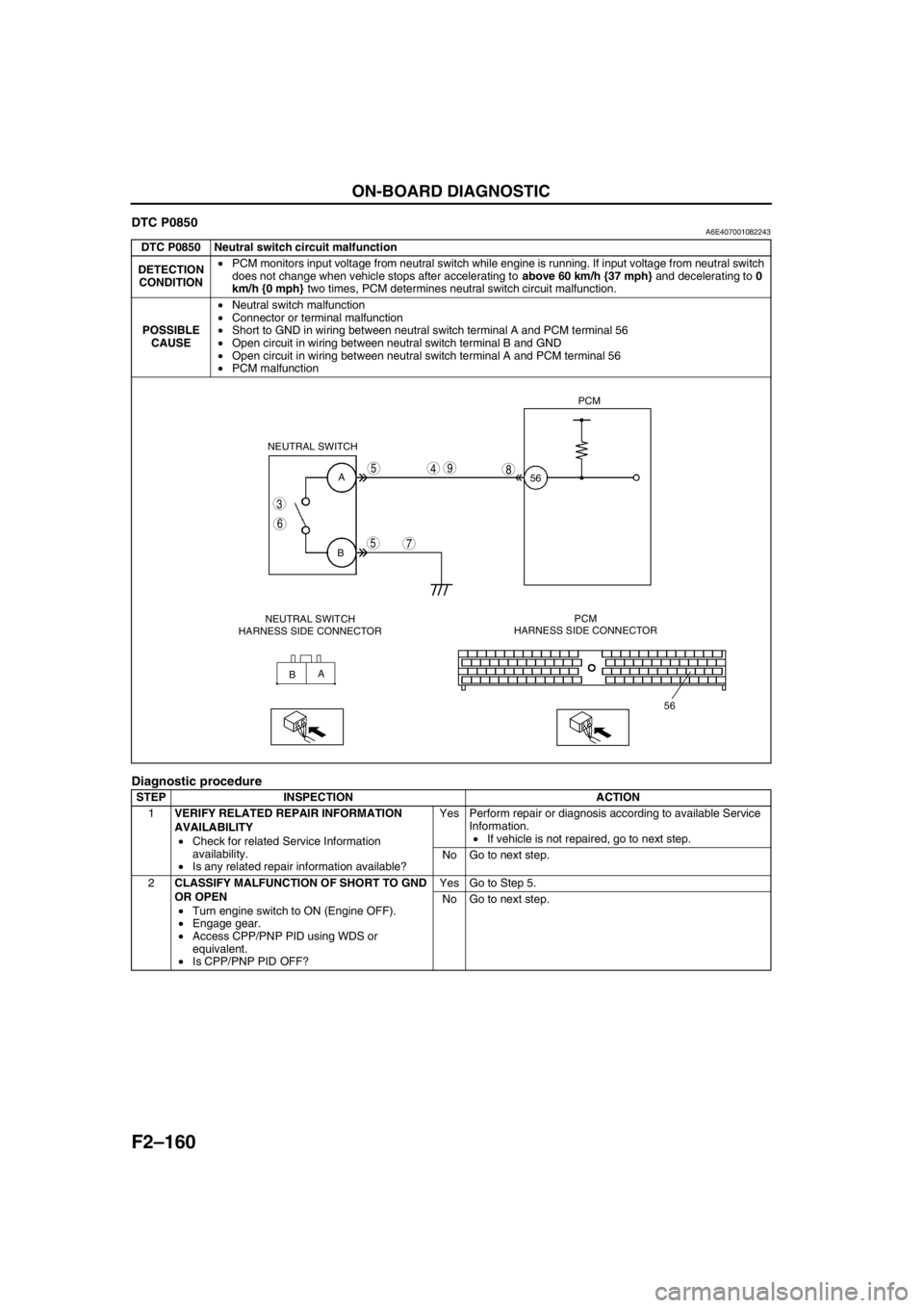
DTC P0850A6E407001082243
Diagnostic procedure
DTC P0850 Neutral switch circuit malfunction
DETECTION
CONDITION•PCM monitors input voltage from neutral switch while engine is running. If input voltage from neutral switch
does not change when vehicle stops after accelerating to above 60 km/h {37 mph} and decelerating to 0
km/h {0 mph} two times, PCM determines neutral switch circuit malfunction.
POSSIBLE
CAUSE•Neutral switch malfunction
•Connector or terminal malfunction
•Short to GND in wiring between neutral switch terminal A and PCM terminal 56
•Open circuit in wiring between neutral switch terminal B and GND
•Open circuit in wiring between neutral switch terminal A and PCM terminal 56
•PCM malfunction
STEP INSPECTION ACTION
1VERIFY RELATED REPAIR INFORMATION
AVAILABILITY
•Check for related Service Information
availability.
•Is any related repair information available?Yes Perform repair or diagnosis according to available Service
Information.
•If vehicle is not repaired, go to next step.
No Go to next step.
2CLASSIFY MALFUNCTION OF SHORT TO GND
OR OPEN
•Turn engine switch to ON (Engine OFF).
•Engage gear.
•Access CPP/PNP PID using WDS or
equivalent.
•Is CPP/PNP PID OFF?Yes Go to Step 5.
No Go to next step.
A
B
A
B NEUTRAL SWITCH
56PCM
56
3
6
5
5
7
498
NEUTRAL SWITCH
HARNESS SIDE CONNECTORPCM
HARNESS SIDE CONNECTOR
Page 314 of 909

F2–162
ON-BOARD DIAGNOSTIC
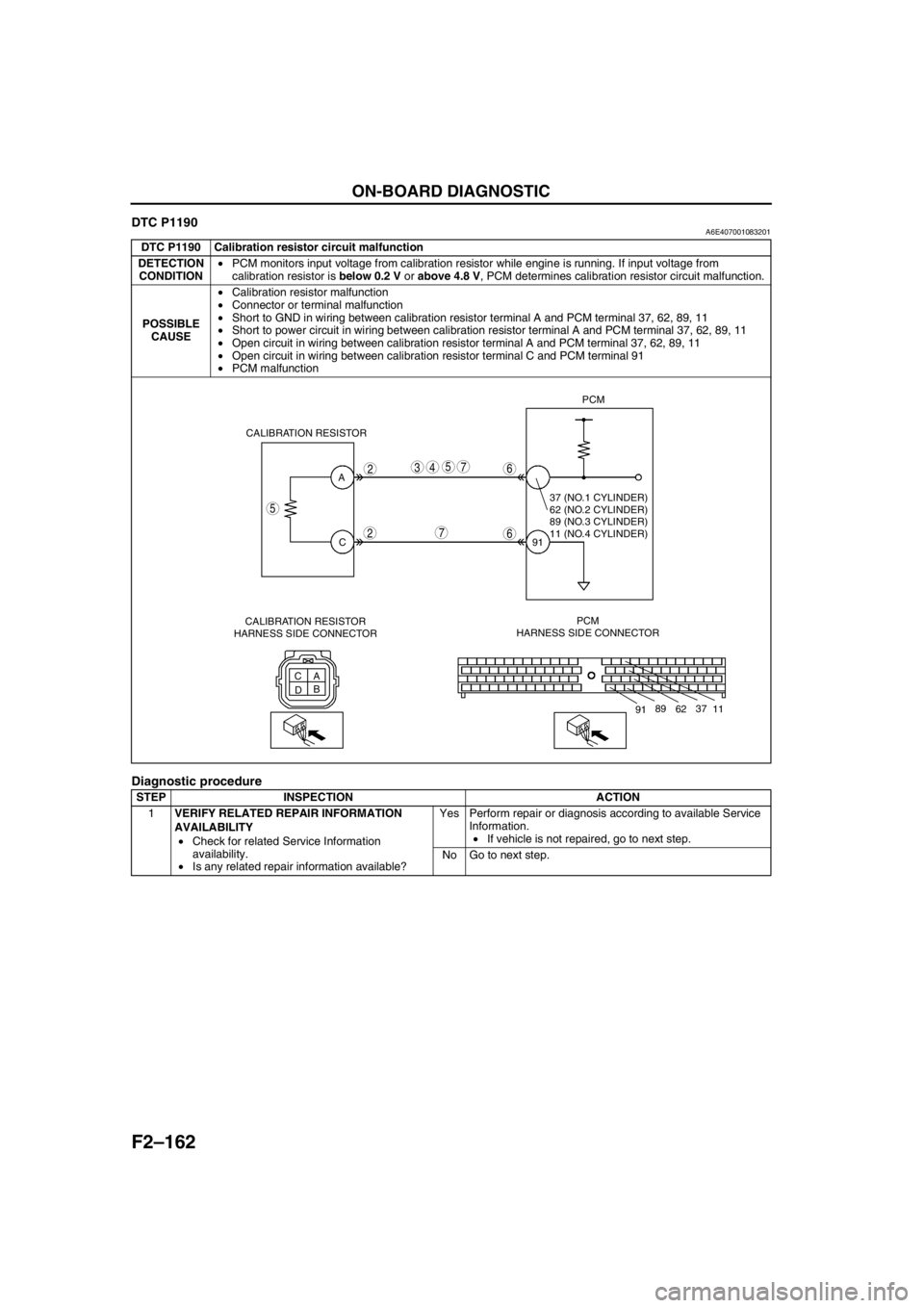
DTC P1190A6E407001083201
Diagnostic procedure
DTC P1190 Calibration resistor circuit malfunction
DETECTION
CONDITION•PCM monitors input voltage from calibration resistor while engine is running. If input voltage from
calibration resistor is below 0.2 V or above 4.8 V, PCM determines calibration resistor circuit malfunction.
POSSIBLE
CAUSE•Calibration resistor malfunction
•Connector or terminal malfunction
•Short to GND in wiring between calibration resistor terminal A and PCM terminal 37, 62, 89, 11
•Short to power circuit in wiring between calibration resistor terminal A and PCM terminal 37, 62, 89, 11
•Open circuit in wiring between calibration resistor terminal A and PCM terminal 37, 62, 89, 11
•Open circuit in wiring between calibration resistor terminal C and PCM terminal 91
•PCM malfunction
STEP INSPECTION ACTION
1VERIFY RELATED REPAIR INFORMATION
AVAILABILITY
•Check for related Service Information
availability.
•Is any related repair information available?Yes Perform repair or diagnosis according to available Service
Information.
•If vehicle is not repaired, go to next step.
No Go to next step.
A
C
C
A
DBPCM
HARNESS SIDE CONNECTOR91PCM
CALIBRATION RESISTOR
5
2
2
5437
7
6
6
11 37
62 89
91
37 (NO.1 CYLINDER)
62 (NO.2 CYLINDER)
89 (NO.3 CYLINDER)
11 (NO.4 CYLINDER)
CALIBRATION RESISTOR
HARNESS SIDE CONNECTOR
Page 316 of 909

F2–164
ON-BOARD DIAGNOSTIC
DTC P2228A6W407001082244
Diagnostic procedure
End Of Sie
DTC P2229A6E407001082245
Diagnostic procedure
End Of Sie
DTC P2228 BARO sensor circuit low input
DETECTION
CONDITION•PCM monitors input voltage from BARO sensor while engine is running. If input voltage from BARO sensor
is below 0.7 V, PCM determines BARO sensor circuit low input.
POSSIBLE
CAUSE•BARO sensor malfunction
•PCM malfunction
STEP INSPECTION ACTION
1PERFORM DTC CONFIRMATION PROCEDURE
•Perform “DTC Confirmation Procedure”.
(See F2–85 DTC CONFIRMATION
PROCEDURE)
•Is same DTC present during KOEO or KOER
self-test?Yes Go to next step.
No Intermittent concern exists. Go to “Intermittent Concern
Troubleshooting”.
(See F2–227 INTERMITTENT CONCERN
TROUBLESHOOTING)
2VERIFY TROUBLESHOOTING OF DTC P2228
COMPLETED
•Clear DTC from PCM memory using WDS or
equivalent.
•Perform KOEO/KOER self-test.
(See F2–26 KOEO/KOER SELF-TEST)
•Is same DTC present?Yes Replace PCM, go to next step.
(See F2–64 PCM REMOVAL/INSTALLATION)
No Go to next step.
3VERIFY AFTER REPAIR PROCEDURE
•Perform “After Repair Procedure”.
(See F2–86 AFTER REPAIR PROCEDURE)
•Is there any DTC present?Yes Go to applicable DTC inspection.
(See F2–87 DTC TABLE)
No Troubleshooting completed.
DTC P2229 BARO sensor circuit high input
DETECTION
CONDITION•PCM monitors input voltage from BARO sensor while engine is running. If input voltage from BARO sensor
is above 4.5 V, PCM determines BARO sensor circuit high input.
POSSIBLE
CAUSE•BARO sensor malfunction
•PCM malfunction
STEP INSPECTION ACTION
1PERFORM DTC CONFIRMATION PROCEDURE
•Perform “DTC Confirmation Procedure”.
(See F2–85 DTC CONFIRMATION
PROCEDURE)
•Is same DTC present during KOEO or KOER
self-test?Yes Go to next step.
No Intermittent concern exists. Go to “Intermittent Concern
Troubleshooting”.
(See F2–227 INTERMITTENT CONCERN
TROUBLESHOOTING)
2VERIFY TROUBLESHOOTING OF DTC P2229
COMPLETED
•Clear DTC from PCM memory using WDS or
equivalent.
•Perform KOEO/KOER self-test.
(See F2–26 KOEO/KOER SELF-TEST)
•Is same DTC present?Yes Replace PCM, go to next step.
(See F2–64 PCM REMOVAL/INSTALLATION)
No Go to next step.
3VERIFY AFTER REPAIR PROCEDURE
•Perform “After Repair Procedure”.
(See F2–86 AFTER REPAIR PROCEDURE)
•Is there any DTC present?Yes Go to applicable DTC inspection.
(See F2–87 DTC TABLE)
No Troubleshooting completed.
Page 320 of 909

F2–168
TROUBLESHOOTING
×: Applicable
Troubleshooting item
1 Melting of main or other fuses
2 MIL illuminates
3 Will not crank
4 Hard start/long crank/erratic start/erratic crank×××
5 Engine stalls After start/at idle×××
6 Cranks normally but will not start××
7 Slow return to idle×
8 Engine runs rough/rolling idle××××
9 Fast idle/runs on×
10 Low idle/stalls during deceleration××
11Engine stalls/quits Acceleration/cruise××××
Engine runs rough Acceleration/cruise×××× ×
Misses Acceleration/cruise××××××
Buck/jerk Acceleration/cruise/ deceleration××××××
Hesitation/stumble Acceleration××××××
Surges Acceleration/cruise××××××
12 Lack/loss of power Acceleration/cruise×××××××
13 Knocking/pinging×××××
14 Poor fuel economy××××
15 Emissions compliance× ××××××
16 High oil consumption/leakage
17 Cooling system concerns Overheating×× × ×
18 Cooling system concerns Runs cold××
19 Excessive black smoke××××
20 Fuel odor (in engine compartment)
21 Engine noise××
22 Vibration concerns (engine)×× ×
23 A/C does not work sufficiently
24 A/C always on or A/C compressor runs continuously
25 A/C does not cut off under wide open throttle conditions
26 Constant voltage
Improper engine coolant levelWater and anti-freeze mixture is improperCooling system malfunction (Radiator, hose,
over-flow system, thermostat, etc.)Cooling fan system malfunctionEngine or transaxle mounts are improperly installedCooling fan No.1 or No.2 seat are improperFuel qualityEngine overheatingIntake-air system clogging or restrictionAir leakage from intake-air systemVSC system malfunctionVacuum leakage
Page 321 of 909

TROUBLESHOOTING
F2–169
F2
×: Applicable
Troubleshooting item
1 Melting of main or other fuses
2 MIL illuminates×× × ×
3 Will not crank
4 Hard start/long crank/erratic start/erratic crank×× ×××××××
5 Engine stalls After start/at idle×× ×××××××
6 Cranks normally but will not start×× ×××××××
7 Slow return to idle××××××××
8 Engine runs rough/rolling idle×××××××××
9 Fast idle/runs on×
10 Low idle/stalls during deceleration××××××××××
11Engine stalls/quits Acceleration/cruise× × ×××××××
Engine runs rough Acceleration/cruise× ××××××××××
Misses Acceleration/cruise× ××××××××××
Buck/jerk Acceleration/cruise/ deceleration× ××××××××××
Hesitation/stumble Acceleration× ××××××××××
Surges Acceleration/cruise× ×× ×××××××
12 Lack/loss of power Acceleration/cruise××× ×××××××××
13 Knocking/pinging××××× ××× × ×
14 Poor fuel economy××× ×××××× ×
15 Emissions compliance×××××××××××××
16 High oil consumption/leakage×
17 Cooling system concerns Overheating×
18 Cooling system concerns Runs cold
19 Excessive black smoke××× × ××× ×××
20 Fuel odor (in engine compartment)××
21 Engine noise× ××× ×
22 Vibration concerns (engine)
23 A/C does not work sufficiently
24 A/C always on or A/C compressor runs continuously
25 A/C does not cut off under wide open throttle conditions
26 Constant voltage
Turbocharger malfunctionCarge air cooler malfunctionVBC system malfunctionGlow system malfunctionIncorrect fuel injection timingIncorrect idle speedCKP sensor is damaged (e.g.: open or short circuits)CKP sensor pulse wheel is damagedImproper gap between CKP sensor and pulse wheelSupply pump malfunctionSuction control valve malfunctionFuel pressure limiter malfunctionFuel line restriction or clogging
Page 324 of 909

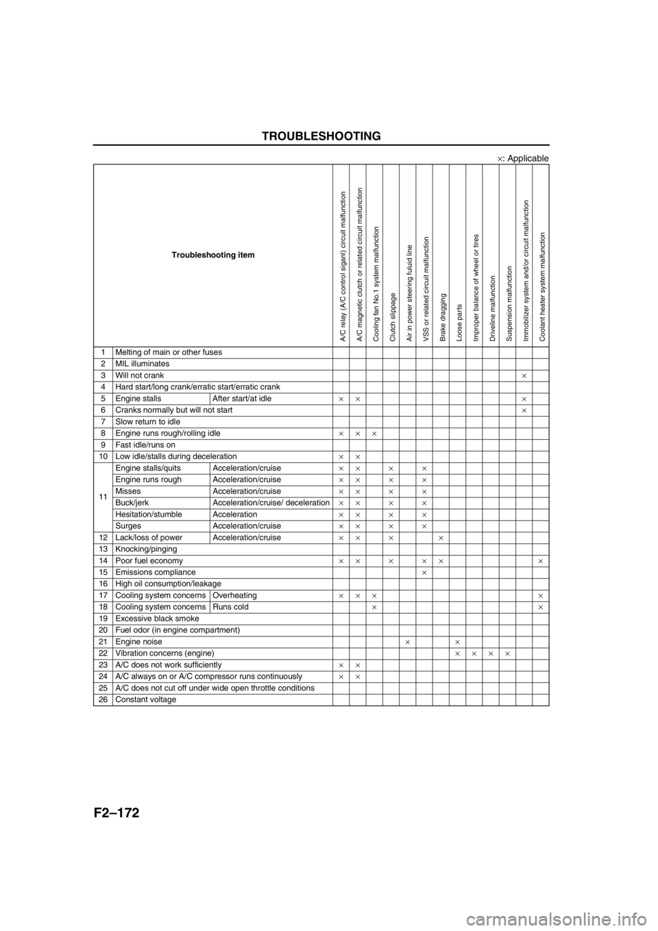
F2–172
TROUBLESHOOTING
×: Applicable
End Of Sie
Troubleshooting item
1 Melting of main or other fuses
2 MIL illuminates
3 Will not crank×
4 Hard start/long crank/erratic start/erratic crank
5 Engine stalls After start/at idle×× ×
6 Cranks normally but will not start×
7 Slow return to idle
8 Engine runs rough/rolling idle×××
9 Fast idle/runs on
10 Low idle/stalls during deceleration××
11Engine stalls/quits Acceleration/cruise××××
Engine runs rough Acceleration/cruise××××
Misses Acceleration/cruise××××
Buck/jerk Acceleration/cruise/ deceleration××××
Hesitation/stumble Acceleration××××
Surges Acceleration/cruise××××
12 Lack/loss of power Acceleration/cruise×× × ×
13 Knocking/pinging
14 Poor fuel economy××××× ×
15 Emissions compliance×
16 High oil consumption/leakage
17 Cooling system concerns Overheating××× ×
18 Cooling system concerns Runs cold××
19 Excessive black smoke
20 Fuel odor (in engine compartment)
21 Engine noise××
22 Vibration concerns (engine)××××
23 A/C does not work sufficiently××
24 A/C always on or A/C compressor runs continuously××
25 A/C does not cut off under wide open throttle conditions
26 Constant voltage
A/C relay (A/C control siganl) circuit malfunctionA/C magnetic clutch or related circuit malfunctionCooling fan No.1 system malfunctionClutch slippageAir in power steering fuluid lineVSS or related circuit malfunctionBrake draggingLoose partsImproper balance of wheel or tiresDriveline malfunctionSuspension malfunctionImmobilizer system and/or circuit malfunctionCoolant heater system malfunction
Page 325 of 909
![MAZDA 6 2002 Suplement Manual PDF TROUBLESHOOTING
F2–173
F2
NO.1 MELTING OF MAIN OR OTHER FUSESA6E408018881203
End Of Sie
1 Melting of main or other fuses
[TROUBLESHOOTING HINTS]
Inspect condition of fuse.
Damaged fuse Related wiri MAZDA 6 2002 Suplement Manual PDF TROUBLESHOOTING
F2–173
F2
NO.1 MELTING OF MAIN OR OTHER FUSESA6E408018881203
End Of Sie
1 Melting of main or other fuses
[TROUBLESHOOTING HINTS]
Inspect condition of fuse.
Damaged fuse Related wiri](/img/28/57057/w960_57057-324.png)
TROUBLESHOOTING
F2–173
F2
NO.1 MELTING OF MAIN OR OTHER FUSESA6E408018881203
End Of Sie
1 Melting of main or other fuses
[TROUBLESHOOTING HINTS]
Inspect condition of fuse.
Damaged fuse Related wiring harness
MAINMAIN fuse
•BTN fuse
•FAN fuse
•AD FAN fuse
•IG KEY 2 fuse
IG KEY 1IG KEY 1 fuse
•Engine switch
—ENGINE fuse
FUEL PUMPFUEL PUMP fuse
•Fuel warmer
•PCM control relay
BTNBTN fuse
•ROOM fuse
IG KEY 2IG KEY 2 fuse
•Engine switch
ROOMROOM fuse
•DLC-2
ENGINEENGINE fuse
•PCM
INJINJ fuse
•PCM
•IDM
•MAF/IAT sensor
•VSC solenoid valve
•VBC solenoid valve
•EGR control solenoid valve
•EGR solenoid valve (vacuum)
•EGR solenoid valve (vent)
•Intake shutter solenoid valve (half)
•Intake shutter solenoid valve (full)
GLOWGLOW fuse
•Glow plug relay
—Glow plug
—GLOW SIG
ENG+BENG+B fuse
•PCM
FANFAN fuse
•Cooling fan relay No.2
AD FANAD FAN fuse
•Cooling fan relay No.1
Shorted harness
Repair shorted harness and replace fuseFuseDeterioration
Replace fuse