wiring MAZDA 6 2002 Workshop Manual Suplement
[x] Cancel search | Manufacturer: MAZDA, Model Year: 2002, Model line: 6, Model: MAZDA 6 2002Pages: 909, PDF Size: 17.16 MB
Page 2 of 909

VEHICLE IDENTIFICATION NUMBERS (VIN)
U.K. specs.
JMZ GG12R20# 100001—
JMZ GG12T20# 100001—
JMZ GG14R20# 100001—
JMZ GG14T20# 100001—
JMZ GY19320# 100001—
JMZ GY19820# 100001—
JMZ GY19F20# 100001—
JMZ GY19F50# 100001—
JMZ GY19R20# 100001—
JMZ GY19T20# 100001—
JMZ GY89370# 100001—
European (L.H.D.) specs.
JMZ GG12R2✻# 100001—
JMZ GG12T2✻# 100001—
JMZ GG14R2✻# 100001—
JMZ GG14T2✻# 100001—JMZ GY1932✻# 100001—
JMZ GY1982✻# 100001—
JMZ GY19F2✻# 100001—
JMZ GY19F5✻# 100001—
JMZ GY19R2✻# 100001—
JMZ GY19T2✻# 100001—
JMZ GY8937✻# 100001—
GCC specs.
JM7 GG32F✻✻# 100001—
JM7 GG42F✻✻# 100001—
JM7 GG34F✻✻# 100001—
JM7 GG44F✻✻# 100001—
JM7 GY49F✻✻# 100001—
JM7 GY39F✻✻# 100001—
JM7 GY49F✻0# 100001—
JM7 GY39F✻0# 100001—
RELATED MATERIALS
Mazda6 Training Manual
(European (L.H.D. U.K.), GCC specs.) . . . . . . . . . . . . 3359–1*–02C
Mazda6 Workshop Manual
(European (L.H.D. U.K.), GCC specs.) . . . . . . . . . . . . 1730–1*–02C
Engine Workshop Manual L8, LF, L3 . . . . . . . . . . . . . . 1731–1*–02C
Engine Workshop Manual MZR–CD (RF Turbo) . . . . . 1744–1E–02D
Manual Transaxle Workshop Manual G35M–R . . . . . . 1732–1*–02C
Manual Transaxle Workshop Manual A65M–R . . . . . . 1739–1E–02D
Automatic Transaxle Workshop Manual FN4A–EL . . . 1623–10–98E
Automatic Transaxle Workshop Manual
Supplement FN4A–EL . . . . . . . . . . . . . . . . . . . . . . . . . 1746–1*–02C
Automatic Transaxle Workshop Manual JA5A–EL . . . 1738–1E–02D
Automatic Transaxle Workshop Manual
Supplement JA5AX–EL . . . . . . . . . . . . . . . . . . . . . . . . 1765–1*–02H
Mazda6 Wiring Diagram
(European (L.H.D.), GCC specs.) . . . . . . . . . . . . . . . . 5558–1*–02G
Mazda6 Wiring Diagram
(U.K. specs.) . . . . . . . . . . . . . . . . . . . . . . . . . . . . . . . . . 5559–1*–02G
Mazda6 Bodyshop Manual
(European (L.H.D. U.K.), GCC specs.) . . . . . . . . . . . . 3360–1*–02C
Mazda6 Bodyshop Manual Supplement
(European (L.H.D. U.K.), GCC specs.) . . . . . . . . . . . . 3368–1*–02I
EOBD Training Manual
(European (L.H.D. U.K.), Australian specs.) . . . . . . . 3345–1*–00B
* : Indicates the printing location
E: Europe
0: Japan
Page 26 of 909

B1–4
OUTLINE, ENGINE
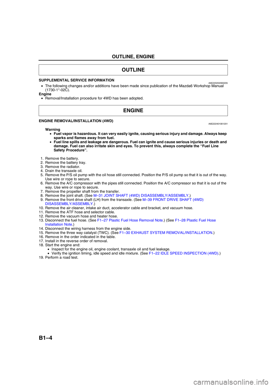
SUPPLEMENTAL SERVICE INFORMATIONA6E220202000205•The following changes and/or additions have been made since publication of the Mazda6 Workshop Manual
(1730-1*-02C).
Engine
•Removal/Installation procedure for 4WD has been adopted.
End Of Sie
ENGINE REMOVAL/INSTALLATION (4WD)A6E222401001201
Warning
•Fuel vapor is hazardous. It can very easily ignite, causing serious injury and damage. Always keep
sparks and flames away from fuel.
•Fuel line spills and leakage are dangerous. Fuel can ignite and cause serious injuries or death and
damage. Fuel can also irritate skin and eyes. To prevent this, always complete the “Fuel Line
Safety Procedure”.
1. Remove the battery.
2. Remove the battery tray.
3. Remove the radiator.
4. Drain the transaxle oil.
5. Remove the P/S oil pump with the oil hose still connected. Position the P/S oil pump so that it is out of the way.
Use wire or rope to secure.
6. Remove the A/C compressor with the pipes still connected. Position the A/C compressor so that it is out of the
way. Use wire or rope to secure.
7. Remove the propeller shaft from the transfer.
8. Remove the joint shaft. (See M–31 JOINT SHAFT (4WD) DISASSEMBLY/ASSEMBLY.)
9. Remove the front drive shaft (LH) from the transaxle. (See M–39 FRONT DRIVE SHAFT (4WD)
DISASSEMBLY/ASSEMBLY.)
10. Remove the air cleaner, intake air duct, accelerator cable and bracket, and vacuum hose.
11. Remove the ATF hose and selector cable.
12. Remove the vacuum hose and heater hose.
13. Disconnect the fuel hose. (See F1–27 Plastic Fuel Hose Removal Note.) (See F1–28 Plastic Fuel Hose
Installation Note.)
14. Disconnect the wiring harness from the engine side.
15. Remove the three way catalyst (TWC). (See F1–30 EXHAUST SYSTEM REMOVAL/INSTALLATION.)
16. Remove in the order indicated in the table.
17. Install in the reverse order of removal.
18. Start the engine and:
•Inspect for the engine oil, engine coolant, transaxle oil and fuel leakage.
•Verify the ignition timing, idle speed and idle mixture. (See F1–22 IDLE SPEED INSPECTION (4WD).)
19. Perform a road test.
OUTLINE
ENGINE
Page 89 of 909
![MAZDA 6 2002 Workshop Manual Suplement F1–1
F1
F1FUEL AND EMISSION CONTROL SYSTEM
[L8, LF, L3]
OUTLINE.............................................................. F1-2
OUTLINE OF CONSTRUCTION ....................... F1-2
FEATURES ..... MAZDA 6 2002 Workshop Manual Suplement F1–1
F1
F1FUEL AND EMISSION CONTROL SYSTEM
[L8, LF, L3]
OUTLINE.............................................................. F1-2
OUTLINE OF CONSTRUCTION ....................... F1-2
FEATURES .....](/img/28/57057/w960_57057-88.png)
F1–1
F1
F1FUEL AND EMISSION CONTROL SYSTEM
[L8, LF, L3]
OUTLINE.............................................................. F1-2
OUTLINE OF CONSTRUCTION ....................... F1-2
FEATURES ........................................................ F1-2
SPECIFICATIONS ............................................. F1-2
CONTROL SYSTEM DIAGRAM (4WD)............. F1-3
CONTROL SYSTEM WIRING DIAGRAM
(4WD).............................................................. F1-4
FUEL SYSTEM..................................................... F1-9
OUTLINE ........................................................... F1-9
STRUCTURAL VIEW......................................... F1-9
SYSTEM DIAGRAM ........................................ F1-10
FUEL PUMP (TRANSFER).............................. F1-10
QUICK RELEASE CONNECTOR (FUEL TANK
SIDE, TRANSFER HOSE PART) ................. F1-12
EXHAUST SYSTEM........................................... F1-13
OUTLINE ......................................................... F1-13
STRUCTURAL VIEW....................................... F1-13
CONTROL SYSTEM........................................... F1-14
OUTLINE ......................................................... F1-14
STRUCTURAL VIEW (4WD) ........................... F1-16
BLOCK DIAGRAM ........................................... F1-17
CONTROL DEVICE AND CONTROL
RELATIONSHIP CHART .............................. F1-19
CONTROLLER AREA NETWORK (CAN) ....... F1-21
OUTLINE............................................................ F1-22
SUPPLEMENTAL SERVICE
INFORMATION ............................................. F1-22
ENGINE TUNE-UP............................................. F1-22
IDLE SPEED INSPECTION (4WD) ................. F1-22
FUEL SYSTEM................................................... F1-23
FUEL TANK REMOVAL/INSTALLATION ........ F1-23
FUEL PUMP UNIT
REMOVAL/INSTALLATION .......................... F1-26
FUEL HOSE (FUEL TANK SIDE,
TRANSFER HOSE PART)
REMOVAL/INSTALLATION .......................... F1-29
EXHAUST SYSTEM........................................... F1-30
EXHAUST SYSTEM
REMOVAL/INSTALLATION .......................... F1-30
CONTROL SYSTEM........................................... F1-33
PCM INSPECTION (4WD)............................... F1-33
ON-BOARD DIAGNOSTIC................................. F1-50
OUTLINE ......................................................... F1-50
CONTROL DEVICE AND MONITORING
SYSTEM RELATIONSHIP CHART .............. F1-50
DIAGNOSTIC TEST MODE (4WD) ................. F1-50
DTC (4WD) ...................................................... F1-52
OBD DRIVE MODE ......................................... F1-52
DTC TABLE ..................................................... F1-54
TROUBLESHOOTING........................................ F1-57ENGINE SYMPTOM
TROUBLESHOOTING .................................. F1-57
QUICK DIAGNOSTIC CHART ......................... F1-58
NO.14 POOR FUEL ECONOMY ..................... F1-62
NO.22 VIBRATION CONCERNS
(ENGINE) ...................................................... F1-64 FEATURES
SERVICE
Page 92 of 909

F1–4
OUTLINE
CONTROL SYSTEM WIRING DIAGRAM (4WD)A6E390218881205With Immobilizer System
.
2Y
2Z
2AC
1AB
1Y
2K
2A
1J
1G
1M
2E
1P
2H
2U
2R
2P
2S
2D
2G
2J
2M4Z
4W
4AD
4AA
4G
4J
4A
4D
2X
4O
4B
4L
4F
4Q
2T
2Q
2W
4I
9
87
5
4
3
10
19
18
17
15
16
14
13
11
12
20
29
28
27
25
26
24
23
21
22
30
6
1
2
3132
A6E39022001
1 HO2S (front)
2 HO2S (rear)
3 TP sensor
4 MAP sensor
5 BARO sensor6ECT sensor
7 MAF/IAT sensor
8 IAT sensor
9 MAF sensor
10 Controller area network (CAN)
Page 125 of 909

CONTROL SYSTEM
F1–37
F1
Without Using the SST
Caution
•The PCM terminal voltages vary with change in measuring conditions and vehicle conditions.
Always carry out a total inspection of the input systems, output systems, and PCM to determine
the cause of trouble. Otherwise, a wrong diagnosis will be made.
1. Measure the voltage at each terminal.
•If any incorrect voltage is detected, inspect the related system(s), wiring harnesses and connector(s)
referring to the Action column in the terminal voltage table.
Terminal voltage table (Reference)
Terminal Signal Connected to Test conditionVoltage
(V)Action
1A IGT1Ignition coil (No. 1,
4 cylinders)•Inspect using the wave profile.
(See F1–44 Inspection Using An
Oscilloscope (Reference).)•Inspect ignition coil
•Inspect related
harness
1B IGT2Ignition coil (No. 2,
3 cylinders)•Inspect using the wave profile.
(See F1–44 Inspection Using An
Oscilloscope (Reference).)•Inspect ignition coil
•Inspect related
harness
1C GND GND Under any condition Below 1.0•Inspect related
harness
1D GND GND Under any condition Below 1.0•Inspect related
harness
1E—— — ——
1F—— — ——
1G BARO BARO sensor Ignition switch ON (at sea level)Approx.
4.1 V•Inspect BARO sensor
•Inspect related
harness
1H—— — ——
1I—— — ——
1JManifold absolute
pressureMAP sensorIgnition switch ON (Engine OFF)Approx.
4.1•Inspect MAP sensor
•Inspect related
harness
IdleApprox.
1.5
1K Brake Brake switchBrake pedal depressed B+•Inspect brake switch
•Inspect related
harness Brake pedal released Below 1.0
1L—— — ——
1M ECT ECT sensorIgnition switch
ONECT 20 °C
{68 °F}3.04—
3.14•Inspect ECT sensor
•Inspect related
harness ECT 60 °C
{140 °F}1.29—
1.39
1N—— — ——
1O—— — ——
1P MAF MAF sensorIgnition switch ONApprox.
0.7•Inspect MAF sensor
•Inspect related
harness
Idle (after warm up)Approx.
1.3
1B 1A
1E 1D
1C 1H 1G 1J
1F 1I 1M
1L 1N 1K 1T 1Q1P 1S
1O 1R 1W1V
1Z 1Y
1X1AC1AB
1AA 1AD1U 2B 2A
2E 2D
2C 2H 2G 2J
2F 2I 2M
2L 2N 2K 2T 2Q2P 2S
2O 2R 2W2V
2Z 2Y
2X2AC2AB
2AA 2AD2U 3B 3A
3E 3D
3C 3H 3G 3J
3F 3I 3M
3L 3N 3K 3T 3Q3P 3S
3O 3R 3W3V
3Z 3Y
3X3AA3U 4B 4A
4E 4D
4C 4H 4G 4J
4F 4I 4M
4L 4N 4K 4T 4Q4P 4S
4O 4R 4W4V
4Z 4Y
4X4AC4AB
4AA 4AD4U
A6A3940W002
Page 153 of 909
![MAZDA 6 2002 Workshop Manual Suplement F2–1
F2
F2FUEL AND EMISSION CONTROL SYSTEMS
[MZR-CD (RF Turbo)]
OUTLINE.............................................................. F2-3
OUTLINE OF CONSTRUCTION ....................... F2-3
FEATUR MAZDA 6 2002 Workshop Manual Suplement F2–1
F2
F2FUEL AND EMISSION CONTROL SYSTEMS
[MZR-CD (RF Turbo)]
OUTLINE.............................................................. F2-3
OUTLINE OF CONSTRUCTION ....................... F2-3
FEATUR](/img/28/57057/w960_57057-152.png)
F2–1
F2
F2FUEL AND EMISSION CONTROL SYSTEMS
[MZR-CD (RF Turbo)]
OUTLINE.............................................................. F2-3
OUTLINE OF CONSTRUCTION ....................... F2-3
FEATURES ........................................................ F2-3
SPECIFICATIONS ............................................. F2-3
CONTROL SYSTEM DIAGRAM ........................ F2-4
CONTROL SYSTEM WIRING DIAGRAM.......... F2-5
INTAKE-AIR SYSTEM.......................................... F2-8
OUTLINE ........................................................... F2-8
STRUCTURAL VIEW......................................... F2-9
FUEL SYSTEM................................................... F2-10
OUTLINE ......................................................... F2-10
STRUCTURAL VIEW....................................... F2-11
EXHAUST SYSTEM........................................... F2-13
OUTLINE ......................................................... F2-13
STRUCTURAL VIEW....................................... F2-13
EMISSION SYSTEM........................................... F2-14
OUTLINE ......................................................... F2-14
STRUCTURAL VIEW....................................... F2-15
WARM UP OXIDATION CATALYTIC
CONVERTER DESCRIPTION ...................... F2-16
CONTROL SYSTEM........................................... F2-16
OUTLINE ......................................................... F2-16
STRUCTURAL VIEW....................................... F2-18
BLOCK DIAGRAM ........................................... F2-20
CONTROL DEVICE AND CONTROL
RELATIONSHIP CHART .............................. F2-22
CRUISE CONTROL SYSTEM ......................... F2-23
CONTROLLER AREA NETWORK (CAN) ....... F2-24
ON-BOARD DIAGNOSTIC................................. F2-24
OUTLINE ......................................................... F2-24
DTC.................................................................. F2-24
KOEO/KOER SELF-TEST ............................... F2-26
PID/DATA MONITOR AND RECORD ............. F2-27
SIMULATION TEST ......................................... F2-27
LOCATION INDEX............................................. F2-28
INTAKE-AIR SYSTEM ..................................... F2-28
FUEL SYSTEM ................................................ F2-29
EMISSION SYSTEM........................................ F2-31
CONTROL SYSTEM........................................ F2-32
ENGINE TUNE-UP............................................. F2-34
ENGINE TUNE-UP PREPARATION ............... F2-34
IDLE SPEED INSPECTION ............................. F2-34
CORRECTION PROCEDURE ......................... F2-34
INTAKE-AIR SYSTEM........................................ F2-35
VACUUM TUBE ROUTING DIAGRAM............ F2-35
INTAKE-AIR SYSTEM
REMOVAL/INSTALLATION .......................... F2-36
AIR CLEANER ELEMENT INSPECTION ........ F2-37
TURBOCHARGER INSPECTION ................... F2-38
GUIDE BLADE ACTUATOR INSPECTION ..... F2-39
VARIABLE BOOST CONTROL (VBC)
SOLENOID VALVE INSPECTION ................ F2-40VARIABLE BOOST CONTROL (VBC)
CHECK VALVE INSPECTION ...................... F2-41
VARIABLE SWIRL CONTROL (VSC)
VALVE ACTUATOR INSPECTION ............... F2-41
VARIABLE SWIRL CONTROL (VSC)
SOLENOID VALVE INSPECTION ................ F2-42
GLOW PLUG REMOVAL/INSTALLATION ...... F2-42
GLOW PLUG INSPECTION ............................ F2-43
GLOW PLUG LEAD INSPECTION .................. F2-43
ACCELERATOR PEDAL COMPONENT
REMOVAL/INSTALLATION .......................... F2-44
ACCELERATOR PEDAL COMPONENT
DISASSEMBLY/ASSEMBLY ........................ F2-44
FUEL SYSTEM................................................... F2-45
BEFORE REPAIR PROCEDURE .................... F2-45
AFTER REPAIR PROCEDURE ....................... F2-45
FUEL TANK REMOVAL/INSTALLATION ........ F2-45
FUEL TANK INSPECTION .............................. F2-49
NONRETURN VALVE INSPECTION............... F2-50
FUEL FILTER COMPONENT
REMOVAL/INSTALLATION .......................... F2-50
FUEL FILTER COMPONENT
DISASSEMBLY/ASSEMBLY ........................ F2-51
FUEL WARMER INSPECTION........................ F2-51
SEDIMENTOR WATER DRAINING................. F2-52
SEDIMENTOR SWITCH INSPECTION ........... F2-52
SUPPLY PUMP REMOVAL/INSTALLATION .. F2-53
SUPPLY PUMP INSPECTION......................... F2-54
SUCTION CONTROL VALVE INSPECTION ... F2-54
COMMON RAIL INSPECTION ........................ F2-54
FUEL INJECTOR REMOVAL/INSTALLATION F2-55
FUEL INJECTOR INSPECTION ...................... F2-56
EXHAUST SYSTEM........................................... F2-57
EXHAUST SYSTEM INSPECTION ................. F2-57
EXHAUST SYSTEM
REMOVAL/INSTALLATION .......................... F2-57
EMISSION SYSTEM........................................... F2-59
EGR VALVE REMOVAL/INSTALLATION........ F2-59
EGR VALVE INSPECTION .............................. F2-59
EGR SOLENOID VALVE (VACUUM)
INSPECTION ................................................ F2-60
EGR SOLENOID VALVE (VENT)
INSPECTION ................................................ F2-60
EGR CONTROL SOLENOID VALVE
INSPECTION ................................................ F2-61
INTAKE SHUTTER VALVE ACTUATOR
INSPECTION ................................................ F2-62
INTAKE SHUTTER SOLENOID VALVE
INSPECTION ................................................ F2-63
CONTROL SYSTEM........................................... F2-64
PCM REMOVAL/INSTALLATION .................... F2-64
PCM INSPECTION .......................................... F2-65
PCM CONFIGURATION .................................. F2-68
CLUTCH SWITCH INSPECTION .................... F2-68
NEUTRAL SWITCH INSPECTION .................. F2-69
IDLE SWITCH INSPECTION ........................... F2-70
IDLE SWITCH ADJUSTMENT ......................... F2-71
ACCELERATOR POSITION SENSOR
INSPECTION ................................................ F2-72
ACCELERATOR POSITION SENSOR
ADJUSTMENT .............................................. F2-73 FEATURES
SERVICE
Page 157 of 909

OUTLINE
F2–5
F2
CONTROL SYSTEM WIRING DIAGRAMA6E400218881205
BA
ABA
ABA
ABA
A1A
1B 1C 1D 1E 1F1G
1H2A
2B 2C2D
2E
2F2G 2H
a
b
c
d
e
f
g
30 42
44 4543 1A
1B 1C 1D 1E 1F
13 39
80
28 78
A 57
E5633 1
427 73464
1041038565 9169
E53
79 9
1460
CBD AE C
A
Dh
i
j
k
l
m
n
o C
D
LOCKACCONSTB
ACCIG2IG1ST
AA
M
BA
A
AAB
9
8
7
5
4
3
10
19
18
17
1516
14
131112
20
6
1
2
23
21
22
A6E40022002
Page 192 of 909

F2–40
INTAKE-AIR SYSTEM
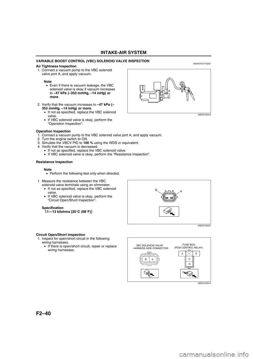
VARIABLE BOOST CONTROL (VBC) SOLENOID VALVE INSPECTIONA6E401013710201Air Tightness Inspection
1. Connect a vacuum pump to the VBC solenoid
valve port A, and apply vacuum.
Note
•Even if there is vacuum leakage, the VBC
solenoid valve is okay if vacuum increases
to –47 kPa {–353 mmHg, –14 inHg} or
more.
2. Verify that the vacuum increases to –47 kPa {–
353 mmHg, –14 inHg} or more.
•If not as specified, replace the VBC solenoid
valve.
•If VBC solenoid valve is okay, perform the
“Operation Inspection”.
Operation Inspection
1. Connect a vacuum pump to the VBC solenoid valve port A, and apply vacuum.
2. Turn the engine switch to ON.
3. Simulate the VBCV PID to 100 % using the WDS or equivalent.
4. Verify that the vacuum is decreased.
•If not as specified, replace the VBC solenoid valve.
•If VBC solenoid valve is okay, perform the “Resistance Inspection”.
Resistance Inspection
Note
•Perform the following test only when directed.
1. Measure the resistance between the VBC
solenoid valve terminals using an ohmmeter.
•If not as specified, replace the VBC solenoid
valve.
•If VBC solenoid valve is okay, perform the
“Circuit Open/Short Inspection”.
Specification
11—13 kilohms [20°C {68°F}]
Circuit Open/Short Inspection
1. Inspect for open/short circuit in the following
wiring harnesses.
•If there is open/short circuit, repair or replace
wiring harnesses.
A
A6E40102012
A B
A6E40102031
AA
BC
DE VBC SOLENOID VALVE
HARNESS SIDE CONNECTORFUSE BOX
(PCM CONTROL RELAY)
A6E40102014
Page 194 of 909

F2–42
INTAKE-AIR SYSTEM
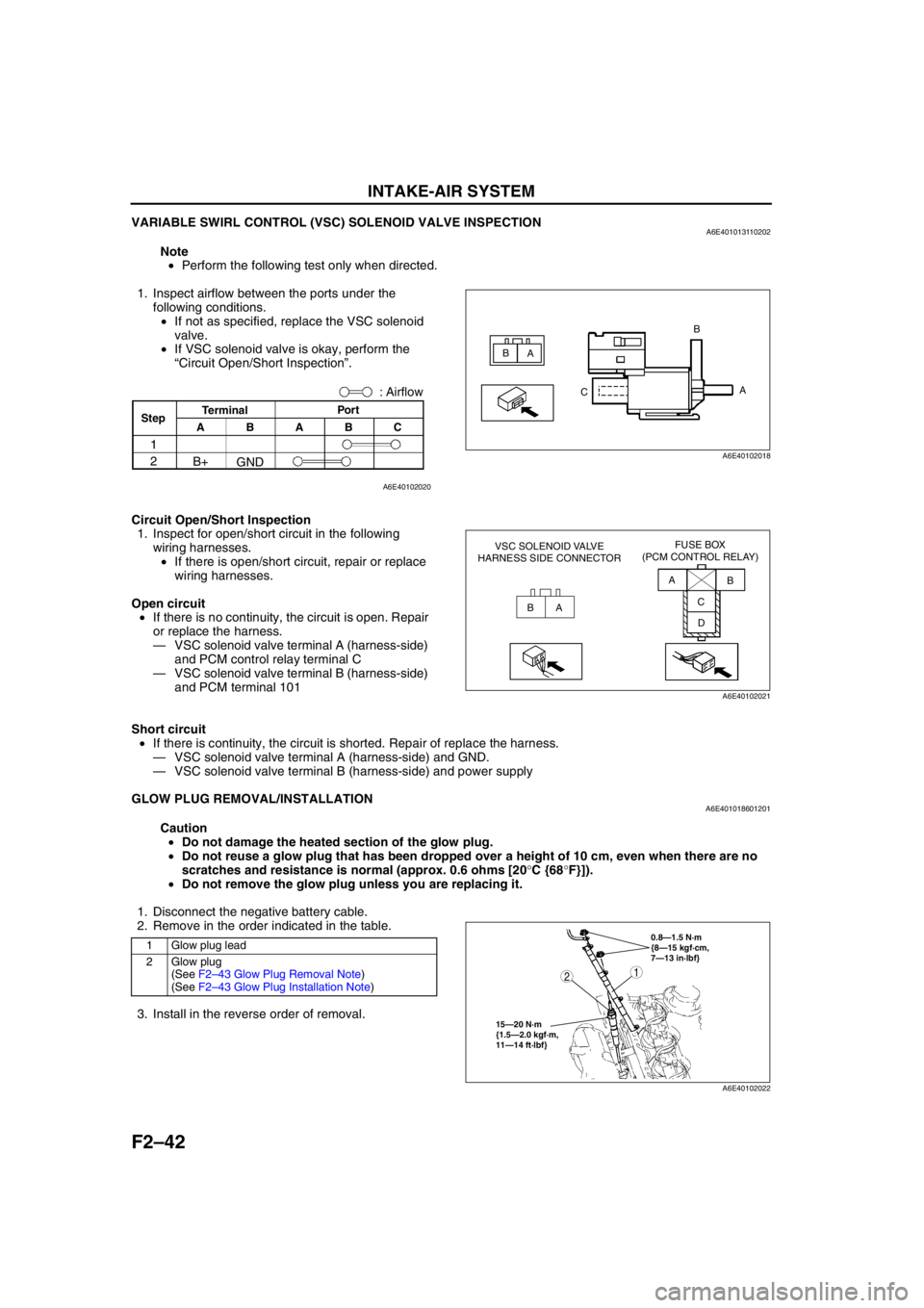
VARIABLE SWIRL CONTROL (VSC) SOLENOID VALVE INSPECTIONA6E401013110202
Note
•Perform the following test only when directed.
1. Inspect airflow between the ports under the
following conditions.
•If not as specified, replace the VSC solenoid
valve.
•If VSC solenoid valve is okay, perform the
“Circuit Open/Short Inspection”.
Circuit Open/Short Inspection
1. Inspect for open/short circuit in the following
wiring harnesses.
•If there is open/short circuit, repair or replace
wiring harnesses.
Open circuit
•If there is no continuity, the circuit is open. Repair
or replace the harness.
—VSC solenoid valve terminal A (harness-side)
and PCM control relay terminal C
—VSC solenoid valve terminal B (harness-side)
and PCM terminal 101
Short circuit
•If there is continuity, the circuit is shorted. Repair of replace the harness.
—VSC solenoid valve terminal A (harness-side) and GND.
—VSC solenoid valve terminal B (harness-side) and power supply
End Of Sie
GLOW PLUG REMOVAL/INSTALLATIONA6E401018601201
Caution
•Do not damage the heated section of the glow plug.
•Do not reuse a glow plug that has been dropped over a height of 10 cm, even when there are no
scratches and resistance is normal (approx. 0.6 ohms [20°C {68°F}]).
•Do not remove the glow plug unless you are replacing it.
1. Disconnect the negative battery cable.
2. Remove in the order indicated in the table.
3. Install in the reverse order of removal.
A
A B
B
C
A6E40102018
: Airflow
Por t
C B
A
GND B+
ABTerminal
Step
1
2
A6E40102020
BAA
B
C
D VSC SOLENOID VALVE
HARNESS SIDE CONNECTORFUSE BOX
(PCM CONTROL RELAY)
A6E40102021
1 Glow plug lead
2Glow plug
(See F2–43 Glow Plug Removal Note)
(See F2–43 Glow Plug Installation Note)0.8—1.5 N·m
{8—15 kgf·cm,
7—13 in·lbf}
15—20 N·m
{1.5—2.0 kgf·m,
11—14 ft·lbf}
12
A6E40102022
Page 203 of 909

FUEL SYSTEM
F2–51
F2
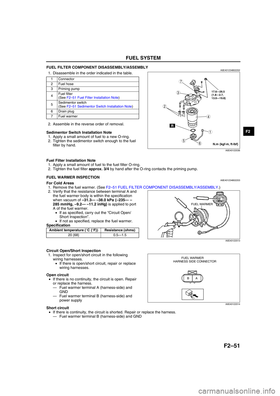
FUEL FILTER COMPONENT DISASSEMBLY/ASSEMBLYA6E4012348022021. Disassemble in the order indicated in the table..
2. Assemble in the reverse order of removal.
Sedimentor Switch Installation Note
1. Apply a small amount of fuel to a new O-ring.
2. Tighten the sedimentor switch enough to the fuel
filter by hand.
Fuel Filter Installation Note
1. Apply a small amount of fuel to the fuel filter O-ring.
2. Tighten the fuel filter approx. 3/4 by hand after the O-ring contacts the priming pump.
End Of Sie
FUEL WARMER INSPECTIONA6E401234802203For Cold Areas
1. Remove the fuel warmer. (See F2–51 FUEL FILTER COMPONENT DISASSEMBLY/ASSEMBLY.)
2. Verify that the resistance between terminal A and
the fuel warmer body is within the specification
when vacuum of –31.3— –38.0 kPa {–235— –
285 mmHg, –9.2— –11.2 inHg} is applied to port
A of the fuel warmer.
•If as specified, carry out the “Circuit Open/
Short Inspection”.
•If not as specified, replace the fuel warmer.
Specification
Circuit Open/Short Inspection
1. Inspect for open/short circuit in the following
wiring harnesses.
•If there is open/short circuit, repair or replace
wiring harnesses.
Open circuit
•If there is no continuity, the circuit is open. Repair
or replace the harness.
—Fuel warmer terminal A (harness-side) and
GND
—Fuel warmer terminal B (harness-side) and
power supply
Short circuit
•If there is continuity, the circuit is shorted. Repair or replace the harness.
—Fuel warmer terminal B (harness-side) and GND
End Of Sie
1 Connector
2 Fuel hose
3 Priming pump
4Fuel filter
(See F2–51 Fuel Filter Installation Note)
5Sedimentor switch
(See F2–51 Sedimentor Switch Installation Note)
6 Drain plug
7 Fuel warmer
R
17.6—26.5
{1.8—2.7,
13.0—19.8}
7
5
4
3
6
1
2
N.m {kgf·m, ft·lbf}
A6E40122036
Ambient temperature (°C {°F}) Resistance (ohms)
20 {68} 0.5—1.5
FUEL WARMER
B
A6E40122013
A B FUEL WARMER
HARNESS SIDE CONNECTOR
A6E40122014