clutch MAZDA 626 1987 Owners Manual
[x] Cancel search | Manufacturer: MAZDA, Model Year: 1987, Model line: 626, Model: MAZDA 626 1987Pages: 1865, PDF Size: 94.35 MB
Page 803 of 1865
CLUTCH AND FLYWHEEL 6
86U06X-035
86U06X-036
76G06X-025
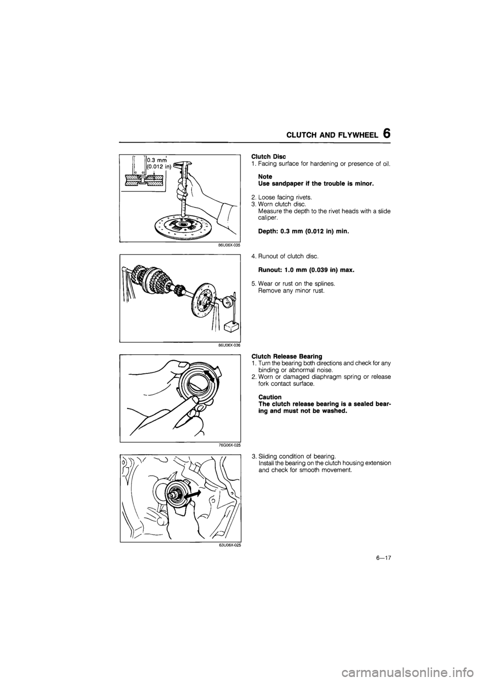
Clutch Disc
1. Facing surface for hardening or presence of oil.
Note Use sandpaper if the trouble is minor.
2. Loose facing rivets.
3. Worn clutch disc.
Measure the depth to the rivet heads with a slide
caliper.
Depth: 0.3 mm (0.012 in) min.
4. Runout of clutch disc.
Runout: 1.0 mm (0.039 in) max.
5. Wear or rust on the splines.
Remove any minor rust.
Clutch Release Bearing
1. Turn the bearing both directions and check for any
binding or abnormal noise.
2. Worn or damaged diaphragm spring or release
fork contact surface.
Caution
The clutch release bearing is a sealed bear-
ing and must not be washed.
3. Sliding condition of bearing.
Install the bearing on the clutch housing extension
and check for smooth movement.
63U06X-025
6-17
Page 804 of 1865
6 CLUTCH AND FLYWHEEL
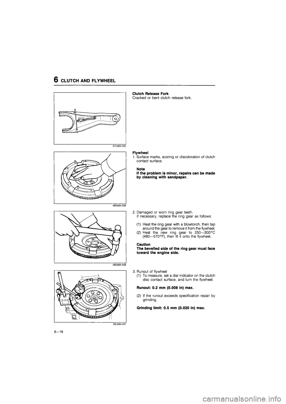
Clutch Release Fork
Cracked or bent clutch release fork.
67U06X-035
4BG06X-028
4BG06X-029
Flywheel
1. Surface marks, scoring or discoloration of clutch
contact surface.
Note
If the problem is minor, repairs can be made
by cleaning with sandpaper.
2. Damaged or worn ring gear teeth.
If necessary, replace the ring gear as follows:
(1) Heat the ring gear with a blowtorch, then tap
around the gear to remove
it
from the flywheel.
(2) Heat the new ring gear to 250—300°C
(480—570°F), then fit it onto the flywheel.
Caution
The bevelled side of the ring gear must face
toward the engine side.
3. Runout of flywheel
(1) To measure, set a dial indicator on the clutch
disc contact surface, and turn the flywheel.
Runout: 0.2 mm (0.008 in) max.
(2) If the runout exceeds specification repair by
grinding.
Grinding limit: 0.5 mm (0.020 in) max.
86U06X-037
6-18
Page 805 of 1865
CLUTCH AND FLYWHEEL 6
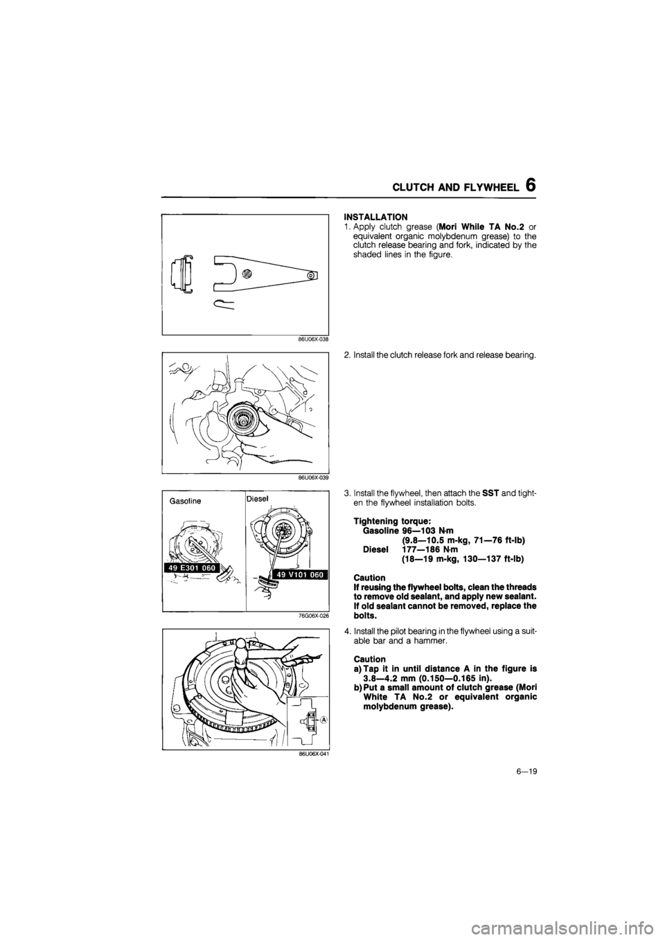
INSTALLATION
1. Apply clutch grease (Mori While TA No.2 or
equivalent organic molybdenum grease) to the
clutch release bearing and fork, indicated by the
shaded lines in the figure.
86U06X-038
2. Install the clutch release fork and release bearing.
86U06X-039
Gasoline Diesel
}
.iSlf
49 E301 060 g^M 1/ j> •«] 49 V101 060
76G06X-026
3. Install the flywheel, then attach the SST and tight-
en the flywheel installation bolts.
Tightening torque:
Gasoline 96—103 N-m
(9.8—10.5 m-kg, 71—76 ft-lb)
Diesel 177—186 N-m
(18—19 m-kg, 130—137 ft-lb)
Caution
If reusing the flywheel bolts, clean the threads
to remove old sealant, and apply new sealant.
If old sealant cannot be removed, replace the
bolts.
4. Install the pilot bearing in the flywheel using a suit-
able bar and a hammer.
Caution
a) Tap it in until distance A in the figure is
3.8—4.2 mm (0.150—0.165 in).
b) Put a small amount of clutch grease (Mori
White TA No.2 or equivalent organic
molybdenum grease).
86U06X-041
6—19
Page 806 of 1865
6 CLUTCH AND FLYWHEEL
86U06X-042
86U06X-043
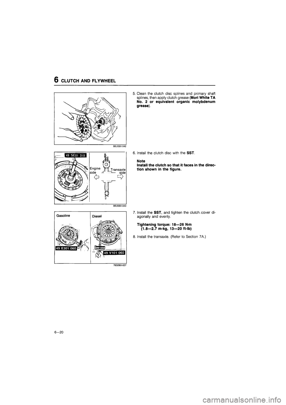
5. Clean the clutch disc splines and primary shaft
splines, then apply clutch grease (Mori White TA
No. 2 or equivalent organic molybdenum
grease).
6. Install the clutch disc with the SST.
Note
Install the clutch so that it faces in the direc-
tion shown in the figure.
7. Install the SST, and tighten the clutch, cover di-
agonally and evenly.
Tightening torque: 18—26 N-m
(1.8—2.7 m-kg, 13—20 ft-lb)
8. Install the transaxle. (Refer to Section 7A.)
76G06X-027
6-20
Page 808 of 1865
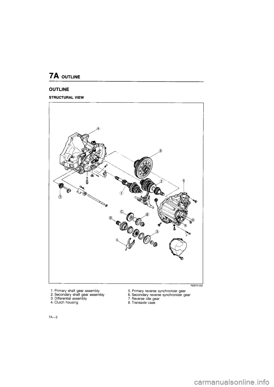
7A OUTLINE
OUTLINE
STRUCTURAL VIEW
76G07A-002
1. Primary shaft gear assembly
2. Secondary shaft gear assembly
3. Differential assembly
4. Clutch housing
5. Primary reverse synchronizer gear
6. Secondary reverse synchronizer gear
7. Reverse idle gear
8. Transaxle case
7A—2
Page 811 of 1865

TROUBLESHOOTING GUIDE 7A
TROUBLESHOOTING GUIDE
Problem Possible cause Remedy Page
Change lever won't Seized change lever ball Replace 7A-58 shift smoothly, or is Seized change control rod joint Replace 7A-58
hard to shift Bent change control rod Replace 7A-58
Too much play in Worn change control rod bushing Replace 7A-58 change lever Weak spring of ball or change lever Replace 7A-58 Worn bushing of ball or change lever Replace 7A—58
Difficult to shift Bent change rod Replace 7A—58
No grease in transmission control Lubricate with grease 7A-58
Insufficient oil Add oil 7A-6
Deterioration of oil quality Replace with oil of 7A-6 specified quality
Wear or play of shift fork or shift rod Replace 7 A—18
Wear of synchronizer ring Replace 7A-27
Wear of synchronizer cone of gear Replace 7A-27
Bed contact of synchronizer ring and cone of Replace 7A-27 gear
Excessive longitudinal play of gears Replace 7A-22
Wear of bearing Adjust or replace 7A—22
Wear of synchronizer key spring Replace 7A-27
Excessive shaft gear bearing preload Adjust 7A-37
Improperly adjusted change guide plate Adjust 7A-20
Won't stay in gear Bent change control rod Replace 7A-58
Worn change control rod bushing Replace 7A-58
Weak change lever ball spring Replace 7A-58
Improperly installed extension bar Tighten 7A-58
Wear of shift fork Replace 7A—22
Wear of clutch hub Replace 7A-27
Worn clutch hub sleeve Replace 7A-27
Worn gear sliding part of both shaft gears Replace 7A-26
Worn gear sliding part of each gear Replace 7A-26
Worn steel sliding groove of control end Replace 7 A—18
Weak spring pressing against steel ball Replace 7A-18
Excessive thrust clearance Replace 7A—33,35
Worn bearing Replace 7A—22
Improperly installed engine mount Tighten 7A—49
Abnormal noise Insufficient oil Add oil 7A-6
Deterioration of oil quality Replace 7A-6
Worn bearing Adjust or replace 7A-22
Worn gear sliding surface of both shaft gears Replace 7A—26
Wear of sliding surfaces of gears Replace 7A-26
Excessive thrust clearance Replace 7A—33,35
Damaged gear teeth Replace with oil of 7A-26
specified quality Foreign material in gears Replace 7A-22
Damaged differential gear, or excessive backlash Adjust or replace 7A—30
76G07A-005
7A-5
Page 812 of 1865

7A ON-VEHICLE MAINTENANCE
61G07X-189
61G07X-190
61G07X-191
ON-VEHICLE MAINTENANCE
TRANSAXLE OIL
Inspection
1. Park the vehicle on level ground.
2. Remove the speedometer cable dust cover, and
disconnect the cable from the speedometer driv-
en gear.
3. After removing the bolt, pull the gear case to re-
move
it
from the housing. (Insert a flat-tipped screw-
driver between the speedometer gear case and
the clutch housing, and use
it
to pry the gear case
loose if necessary.)
4. Check that the oil level is between the "F" and "L".
5. If not, add the necessary amount of the specified
oil through the gear case hole.
Replacement
1. Park the vehicle on level ground.
2. Remove the speedometer driven gear.
(See "Inspection" section above.)
3. Remove the drain plug, and drain the oil.
4. Replace the drain plug, and add the necessary
amount of the specified oil through the speedom-
eter gear case hole.
Specified oil
Type
ATF: DEXRON II
Above -18°C (0°F):
API: GL-4 or GL-5
SAE 80W-90 or SAE 90
Capacity:
3.35 liters (3.6 US qt, 3.0 Imp qt)
76G07A-006
7A—6
Page 816 of 1865

7A REMOVAL
REMOVAL
Fl except DOHC
76G07A-008
1. Battery
2. Main fuse block
3. Air cleaner assembly
4. Ventilation hose
5. Air hose
6. Ground(s)
7. Speedometer cable
8. Clutch release cylinder
9. Canister hose
10. Wheel
11. Splash sheild
12. Extension bar
13. Control rod
14. Stabilizer
15. Joint shaft
16. Gusset plate (rear)
17. Gusset plate (front)
18. Surge tank bracket
19. Starter
20. Under cover
21. Engine mount No.4
22. Engine mount No.2
23. Hunger rubber
24. Crossmember
7 A—10
Page 817 of 1865

REMOVAL 7A
DOHC
76G07A-009
1. Battery
2. Main fuse block
3. Air cleaner assembly
4. Ventilation hose
5. Air hose
6. Ground(s)
7. Speedometer cable
8. Clutch release cylinder
9. Canister hose
10. Wheel
11. Splash sheild
12. Extension bar
13. Control rod
14. Stabilizer
15. Joint shaft
16. Surge tank bracket
17. Starter
18. Engine mount No.4
19. Engine mount No.2
20. Rear member (4WS)
21. Hunger rubber
22. Crossmember
7A—11
Page 818 of 1865

7A REMOVAL
Carburator
76G07A-010
15. Starter
16. Engine mount No.4
17. Engine mount No.2
18. Under cover
19. Hunger rubber
20. Crossmember
1. Battery
2. Air cleaner assembly
3. Ground
4. Speedometer cable
5. Clutch release cylinder
6. Canister hose
7. Wheel
8. Splash sheild
9. Extension bar
10. Control rod
11. Stabilizer
12. Joint shaft
13. Gusset plate (rear)
14. Gusset plate (front)
7 A-12