clutch MAZDA 626 1987 Manual PDF
[x] Cancel search | Manufacturer: MAZDA, Model Year: 1987, Model line: 626, Model: MAZDA 626 1987Pages: 1865, PDF Size: 94.35 MB
Page 767 of 1865

STARTOR (DIESEL ENGINE, 2.0 kW TYPE) 5
Coil spring and steel ball installation
1. Install the coil spring and steel ball to the magnet-
ic switch before installing the over-running clutch
assembly.
2. Assemble the retainer and roller to the idler gear.
4BG04X-100
Brush
(
+
)
Brush installation
1. Assemble the brush holder to the yoke.
2. Assemble the two brushes on the yoke side to the
brush holder.
4BG05X-101
Magnetic switch installation
Align the cut out part with the projection of the mag-
netic switch.
4BG05X-102
INSPECTION
Armature Coil
1. Ground of the armature coil
(1) Check for continuity between the commutator
and the core by using a circuit tester.
(2) Replace the armature if there is continuity.
4BG05X-081
5-61
Page 773 of 1865

5 STARTER (DIESEL ENGINE, 2.0 KW TYPE)
REMOVAL AND INSTALLATION
Removal is as follows:
1. Disconnect the negative battery cable.
2. Disconnect the wiring from the starter.
3. Remove the starter.
Install in the reverse order of removal.
Tightening torque:
Bolts 64—89 N-m
(6.5—9.1 m-kg, 47—66 ft-lb)
B terminal 9.8—11.8 N-m
(1.0—1.2 m-kg, 87—104 in-lb)
76G05X-046
DISASSEMBLY AND ASSEMBLY
1. Disassemble in the numbered order shown in the figure.
2. Assembly in the reverse order of disassembly.
4BG05X-107
1. Magnetic switch 7. Lever
2. Rear cover 8. Cover
3. Brush-holder assembly 9. Drive pinion and over-running
4. Yoke clutch assembly
5. Armature 10. Reduction gear
6. Front housing 11. Center bracket
5—67
Page 775 of 1865

STARTER (DIESEL ENGINE, 2.2 KW TYPE) 5
36G05X-034
36G05X-035
36G05X-036
5. Remove the front cover, and remove the lever and
springs (two).
6. Separate the yoke and center bracket.
7. Remove the cover and pull out the snap ring and
washer.
8. Remove the pinion, over-running clutch assembly
and reduction gear from the center bracket.
36G05X-037
5-69
Page 780 of 1865

5 STARTER (DIESEL ENGINE, 2.2 KW TYPE)
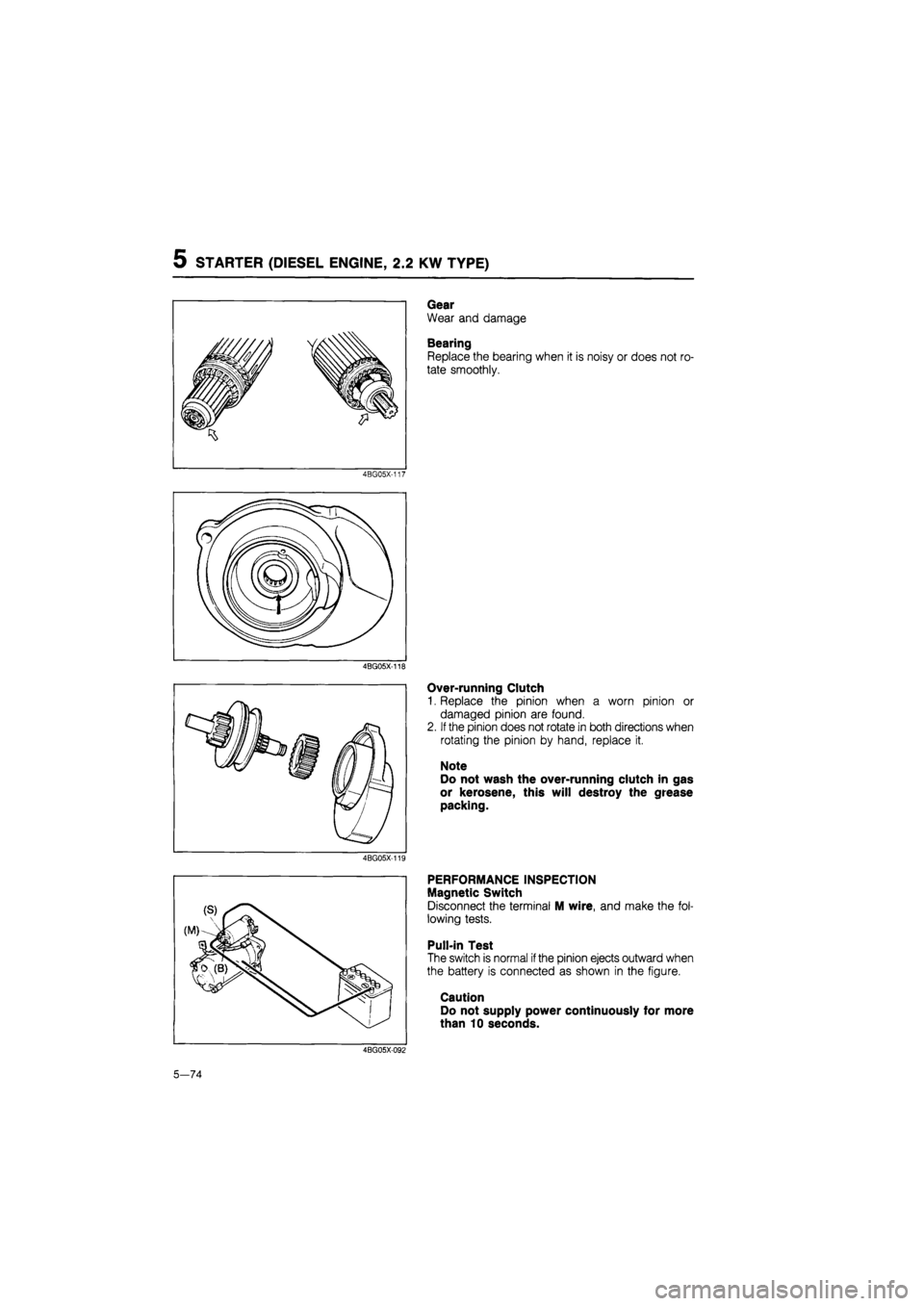
Gear
Wear and damage
Bearing
Replace the bearing when it is noisy or does not ro-
tate smoothly.
4BG05X-117
4BG05X-118
Over-running Clutch
1. Replace the pinion when a worn pinion or
damaged pinion are found.
2.
If
the pinion does not rotate in both directions when
rotating the pinion by hand, replace it.
Note
Do not wash the over-running clutch in gas
or kerosene, this will destroy the grease
packing.
4BG05X-119
PERFORMANCE INSPECTION
Magnetic Switch
Disconnect the terminal M wire, and make the fol-
lowing tests.
Pull-in Test
The switch is normal
if
the pinion ejects outward when
the battery is connected as shown in the figure.
Caution
Do not supply power continuously for more
than 10 seconds.
4BG05X-092
5—74
Page 787 of 1865

CLUTCH
OUTLINE 6— 2
STRUCTURAL VIEW 6— 2
SPECIFICATIONS 6— 3
TROUBLESHOOTING GUIDE 6— 3
ON-VEHICLE MAINTENANCE 6— 4
FLUID LEVEL 6— 4
PEDAL HEIGHT 6— 4
PEDAL FREEPLAY 6— 4
CLUTCH PEDAL 6— 5
REMOVAL 6— 5
INSPECTION 6— 6
INSTALLATION 6— 6
ADJUSTMENT 6— 6
CLUTCH MASTER CYLINDER 6— 7
REMOVAL 6— 7
DISASSEMBLY 6—8
INSPECTION 6— 9
ASSEMBLY 6— 9
INSTALLATION 6—11
CLUTCH RELEASE CYLINDER 6—11
REMOVAL 6—12
DISASSEMBLY 6-12
INSPECTION 6—13
ASSEMBLY 6—13
INSTALLATION 6—14
AIR BLEEDING 6—14
CLUTCH AND FLYWHEEL 6—15
REMOVAL 6—15
INSPECTION 6—16
INSTALLATION 6—19
76G06X-001
Page 788 of 1865

6 OUTLINE
OUTLINE
STRUCTURAL VIEW
LHD
86U06X-002
1. Clutch pedal 4. Clutch pipe 7. Clutch release bearing
2. Assist spring 5. Clutch release cylinder 8. Clutch cover
3. Clutch master cylinder 6. Clutch release fork 9. Clutch disc
6-2
Page 789 of 1865

TROUBLESHOOTING GUIDE 6
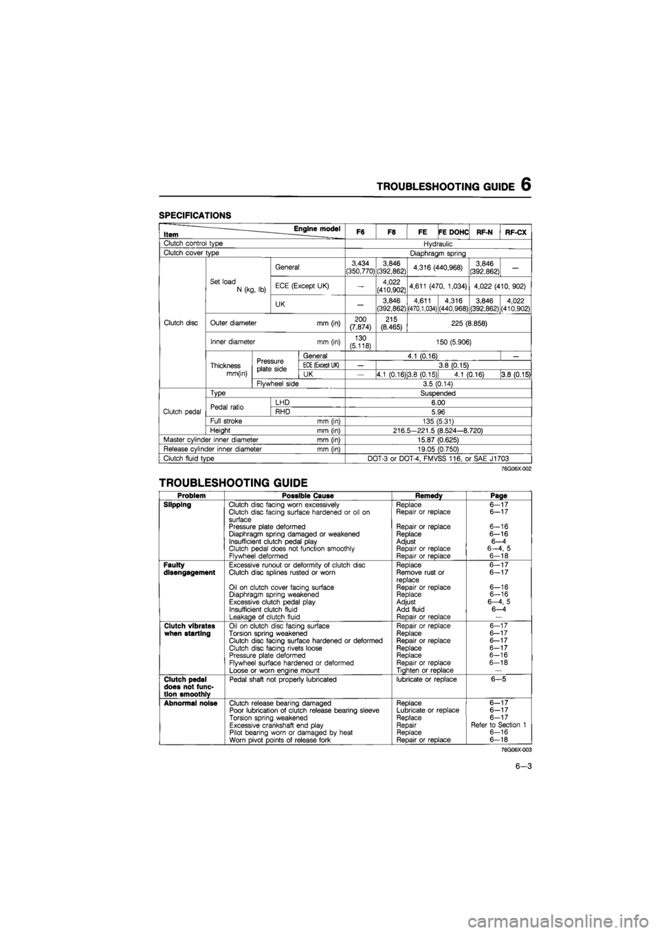
SPECIFICATIONS
Item Engine model F6 F8 FE FE DOHC RF-N RF-CX
Clutch control type Hydraulic
Clutch cover type Diaphragm spring
General 3,434
(350,770) 3,846
(392,862) 4,316 (440,968) 3,846
(392,862) —
Set load
N (kg, lb) ECE (Except UK) — 4,022
(410,902) 4,611 (470, 1,034) 4,022 (410, 902)
UK — 3,846
(392,862)
4,611 (470,1,034) 4,316
(440,968)
3,846 (392,862) 4,022 (410,902)
Clutch disc Outer diameter mm (in) 200 (7.874) 215 (8.465) 225 (8.858)
Inner diameter mm (in) 130 (5.118) 150 (5.906)
Pressure plate side
General 4.1 (0.16) —
Thickness Pressure plate side
ECE
(Except UK) — 3.8 (0.15)
mm(in)
Pressure plate side UK 4.1 (0.16)13.8 (0.15) 4.1 (0.16) 3.8 (0.15)
Flywheel side 3.5 (0.14)
Type Suspended
Pedal ratio LHD 6.00
Clutch pedal Pedal ratio RHD 5.96
Full stroke mm (in) 135 (5.31)
Height mm (in) 216.5-221.5 (8.524-8.720)
Master cylinder inner diameter mm (in) 15.87 (0.625)
Release cylinder inner diameter mm (in) 19.05 (0.750)
Clutch fluid type DOT-3 or DOT-4, FMVSS 116, or SAE J1703
76G06X-002
TROUBLESHOOTING GUIDE
Problem Possible Cause Remedy Page
Slipping Clutch disc facing worn excessively Replace 6—17 Clutch disc facing surface hardened or oil on Repair or replace 6-17
surface Pressure plate deformed Repair or replace 6-16 Diaphragm spring damaged or weakened Replace 6-16 Insufficient clutch pedal play Adjust 6—4 Clutch pedal does not function smoothly Repair or replace 6—4, 5 Flywheel deformed Repair or replace 6-18
Faulty Excessive runout or deformity of clutch disc Replace 6-17 disengagement Clutch disc splines rusted or worn Remove rust or 6—17 replace Oil on clutch cover facing surface Repair or replace 6-16 Diaphragm spring weakened Replace 6-16
Excessive clutch pedal play Adjust 6—4, 5
Insufficient clutch fluid Add fluid 6-4
Leakage of clutch fluid Reoair or reDlace —
Clutch vibrates Oil on clutch disc facing surface Repair or replace 6-17 when starting Torsion spring weakened Replace 6-17 Clutch disc facing surface hardened or deformed Repair or replace 6-17
Clutch disc facing rivets loose Replace 6-17 Pressure plate deformed Replace 6-16
Flywheel surface hardened or deformed Repair or replace 6-18
Loose or worn engine mount Tighten or replace —
Clutch pedal Pedal shaft not properly lubricated lubricate or replace 6-5 does not func-tion smoothlv
Abnormal noise Clutch release bearing damaged Replace 6—17 Poor lubrication of clutch release bearing sleeve Lubricate or replace 6-17
Torsion spring weakened Replace 6-17
Excessive crankshaft end play Repair Refer to Section 1 Pilot bearing worn or damaged by heat Replace 6-16
Worn pivot points of release fork • Reoair or replace 6-18
76G06X-003
6-3
Page 790 of 1865

6 ON-VEHICLE MAINTENANCE
6-4
ON-VEHICLE MAINTENANCE
FLUID LEVEL
1. Clean the area around the reservoir and the reser-
voir cap.
2. Check the fluid level. If the level is near or below
the "MIN" mark, add clutch fluid to the "MAX"
mark.
Fluid specification:
DOT-3 or DOT-4
(FMVSS 116, or SAE J1703)
PEDAL HEIGHT
Inspection
Measure the distance from the upper center of the
pedal pad to the firewall and ensure that the distance
is within specification.
Pedal height A:
216.5—221.5 mm (8.524—8.720 in)
Adjustment
To adjust the pedal height, loosen locknut and turn
stopper bolt or clutch switch.
PEDAL FREEPLAY
Inspection
Depress the pedal lightly by hand and measure the
freeplay to ensure that it is within specification.
Pedal freeplay: 5—13 mm (0.20—0.51 in)
Adjustment
1. Adjust the free play by loosening locknut C and
turning push rod D.
2. Check that the distance from the floor to the cen-
ter of the upper surface of the pedal pad is as
specified or more when the clutch is fully dis-
engaged.
Disengagement height B:
LHD 68 mm (2.7 in)
RHD 85 mm (3.3 in)
3. Tighten locknut C after adjustment.
Page 791 of 1865

CLUTCH PEDAL 6
CLUTCH PEDAL
REMOVAL
Remove in the sequence shown in the figure referring to the removal note.
1. Clip
2. Bolt and nut
3. Spring washer
4. Flat washer
5. Clutch pedal Assembly
6. Rod
7. Adjusting nut
8. Bushing
9. Spring seat
10. Assist spring
11. Spacer
12. Bushings
13. Clip
14. Pin
15. Spring seat
16. Bushing
17. Spacer
18. Bushing
76G06X-006
19. Clip
20. Wave washer
21. Pin
22. Push rod
23. Bushing
24. Stopper rubber
25. Pad
26. Clutch pedal
(p
U-U 0)
r Adjusting nut % £
/ I / Assist spring
"ci*
Removal Note
Before removing the clutch pedal, loosen adjusting
nut of the assist spring to relieve the spring tension.
76G06X-007
6-5
Page 792 of 1865

6 CLUTCH PEDAL
INSPECTION
Check the following, and repair or replace any faulty
parts.
1. Worn or damaged pedal bushing
2. Twisted or bent pedal
3. Worn or damaged pedal pad
76G06X-008
INSTALLATION
Install in the reverse order of removal referring to the
installation note.
Installation Note
Apply grease (lithium base, NLGI No.2) to the
bushings.
76G06X-009
ADJUSTMENT
1. Adjust the pedal height. (Refer to page 6—4.)
2. Check the pedal free play, and adjust if necessary.
(Refer to page 6—4.)
3. Adjust the installation length of the assist spring.
The installation length is adjusted by turning nut
A show in the figure and adjusting dimension B.
Standard dimension:
38.6—39.6 (1.520—1.559 in)
76G06X-010
6-6