ignition MAZDA 626 1987 Workshop Manual
[x] Cancel search | Manufacturer: MAZDA, Model Year: 1987, Model line: 626, Model: MAZDA 626 1987Pages: 1865, PDF Size: 94.35 MB
Page 729 of 1865

ALTERNATOR 5
TROUBLESHOOTING
Preliminary Check
1. Turn the ignition switch ON, and check that
the alternator warning light illuminates.
2. Start the engine, and check that the alternator warning light goes off.
76G05X-024
1. Alternator warning light always not illuminate
76G05X-025
2. Alternator warning light illuminates when engine running
76G05X-026
5-23
Page 732 of 1865

5 ALTERNATOR
TEST 3
1. Turn all electric loads off and release the brake pedal.
2. Check that output current is 5A or more at 2,500—3,000 rpm of the engine speed.
B • , \ B terminal
.w/^y
w
86U05X-013
TEST 4
1. Turn all electric loads off and release the brake pedal.
2. Check that output voltage between S terminal and ground is within specification at
2,500—3,000 rpm of the engin speed.
Voltage: 14.1—14.7V
S terminal
86U05X-072
TEST 5
1. Turn the ignition switch ON.
2. Check that L terminal voltage is within specification.
Voltage: 1—5 V
- L terminal
86U05X-073
5—26
Page 733 of 1865

ALTERNATOR 5
TEST 6
1. Turn the ignition switch ON.
2. Turn all electric loads off and release
the brake pedal.
3. Check that voltage between S terminal
and ground is battery voltage.
S terminal
76G05X-057
76G05X-030
86U05X-074
REMOVAL (GASOLINE)
Remove in the sequence shown in the figure.
1. Disconnect the negative battery terminal.
2. Disconnect the wire and connector from the al-
ternator.
3. Remove the bolts.
4. Remove the V-belt.
-5. Remove the alternator to upper side (LHD) or lower
side (RHD).
REMOVAL (DIESEL)
1. Disconnect the negative battery terminal.
2. Remove the right hand driveshaft (Refer to Sec-
tion 9).
3. Disconnect the wire and connector from the al-
ternator.
4. Loosen the idle pulley nuts and remove the drive
belts.
5. Remove the bolts and remove the alternator from
under the vehicle.
76G05X-031
5-27
Page 744 of 1865
5 STARTER (GASOLINE ENGINE, 0.85, 0.95 KW TYPE)
STARTER (GASOLINE
ENGINE, 0.85, 0.95
KW TYPE)
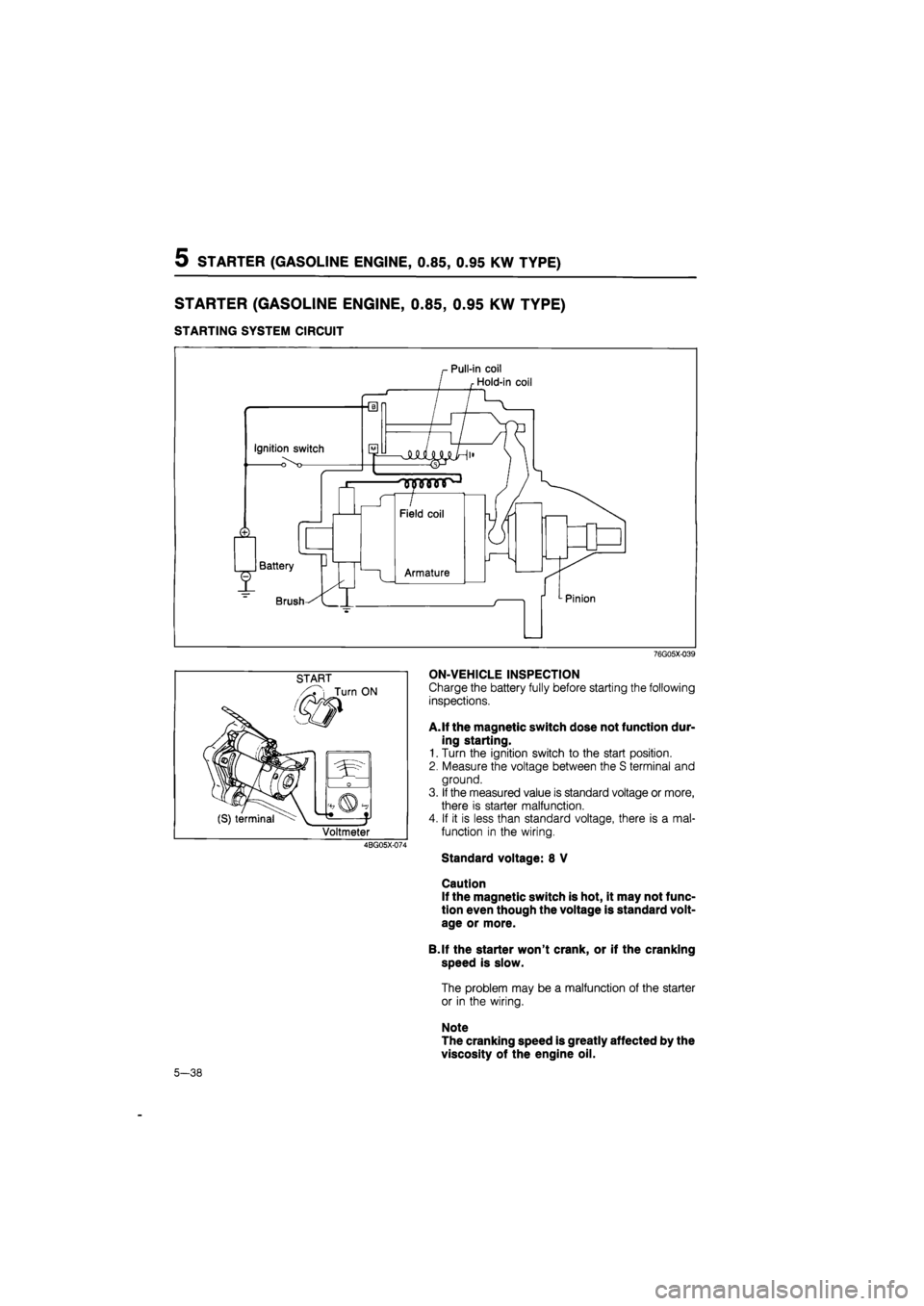
STARTING SYSTEM CIRCUIT
76G05X-039
START
i Turn ON
(S) terminal
0
t* t
Voltmeter
4BG05X-074
ON-VEHICLE INSPECTION
Charge the battery fully before starting the following
inspections.
A. If the magnetic switch dose not function dur-
ing starting.
1. Turn the ignition switch to the start position.
2. Measure the voltage between the S terminal and
ground.
3. If the measured value is standard voltage or more,
there is starter malfunction.
4. If it is less than standard voltage, there is a mal-
function in the wiring.
Standard voltage: 8 V
Caution
If the magnetic switch is hot, it may not func-
tion even though the voltage is standard volt-
age or more.
B.lf the starter won't crank, or if the cranking
speed is slow.
The problem may be a malfunction of the starter
or in the wiring.
Note
The cranking speed is greatly affected by the
viscosity of the engine oil.
5-38
Page 751 of 1865
STARTER (GASOLINE ENGINE, 1.4 KW TYPE) 5
STARTER (GASOLINE
ENGINE, 1.4
KW TYPE)
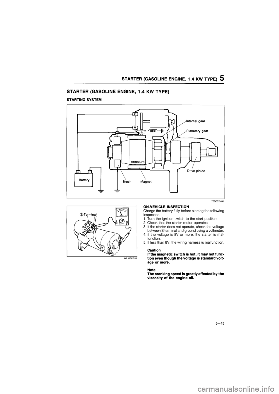
STARTING SYSTEM
76G05X-041
ON-VEHICLE INSPECTION
Charge the battery fully before starting the following
inspection.
1. Turn the ignition switch to the start positron.
2. Check that the starter motor operates.
3. If the starter does not operate, check the voltage
between S terminal and ground using a voltmeter.
4. If the voltage is 8V or more, the starter is mal-
function.
5. If less than 8V, the wiring harness is malfunction.
Caution
If the magnetic switch is hot, it may not func-
tion even though the voltage is standard volt-
age or more.
Note
The cranking speed is greatly affected by the
viscosity of the engine oil.
86U05X-031
5-45
Page 762 of 1865
5 STARTER (DIESEL ENGINE, 2.0 KW TYPE)
STARTER (DIESEL
ENGINE, 2.0
KW TYPE)
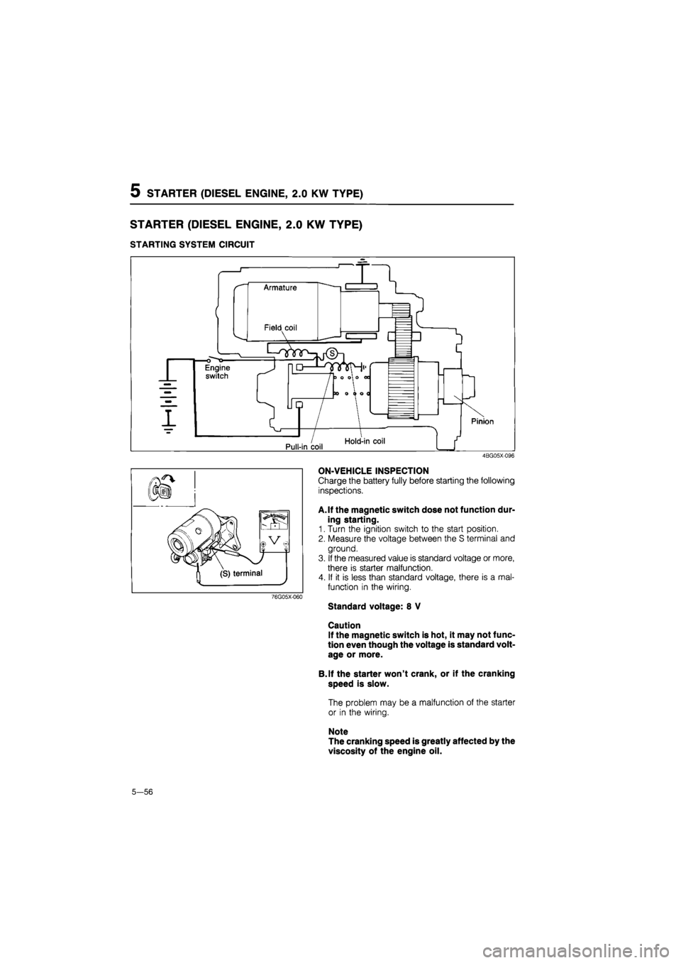
STARTING SYSTEM CIRCUIT
4BG05X-096
76G05X-060
ON-VEHICLE INSPECTION
Charge the battery fully before starting the following
inspections.
A.If the magnetic switch dose not function dur-
ing starting.
1. Turn the ignition switch to the start position.
2. Measure the voltage between the S terminal and
ground.
3. If the measured value is standard voltage or more,
there is starter malfunction.
4. If it is less than standard voltage, there is a mal-
function in the wiring.
Standard voltage: 8 V
Caution
If the magnetic switch is hot, it may not func-
tion even though the voltage is standard volt-
age or more.
B.lf the starter won't crank, or if the cranking
speed is slow.
The problem may be a malfunction of the starter
or in the wiring.
Note
The cranking speed is greatly affected by the
viscosity of the engine oil.
5—56
Page 772 of 1865
5 STARTER (DIESEL ENGINE, 2.0 KW TYPE)
STARTER (DIESEL
ENGINE, 2.2
KW TYPE)
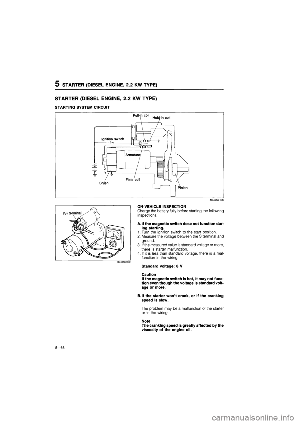
STARTING SYSTEM CIRCUIT
4BG05X-106
76G05X-060
ON-VEHICLE INSPECTION
Charge the battery fully before starting the following
inspections.
A. If the magnetic switch dose not function dur-
ing starting.
1. Turn the ignition switch to the start position.
2. Measure the voltage between the S terminal and
ground.
3.
If
the measured value is standard voltage or more,
there is starter malfunction.
4. If it is less than standard voltage, there is a mal-
function in the wiring.
Standard voltage: 8 V
Caution
If the magnetic switch is hot, it may not func-
tion even though the voltage is standard volt-
age or more.
B.lf the starter won't crank, or if the cranking
speed is slow.
The problem may be a malfunction of the starter
or in the wiring.
Note
The cranking speed is greatly affected by the
viscosity of the engine oil.
5—66
Page 783 of 1865
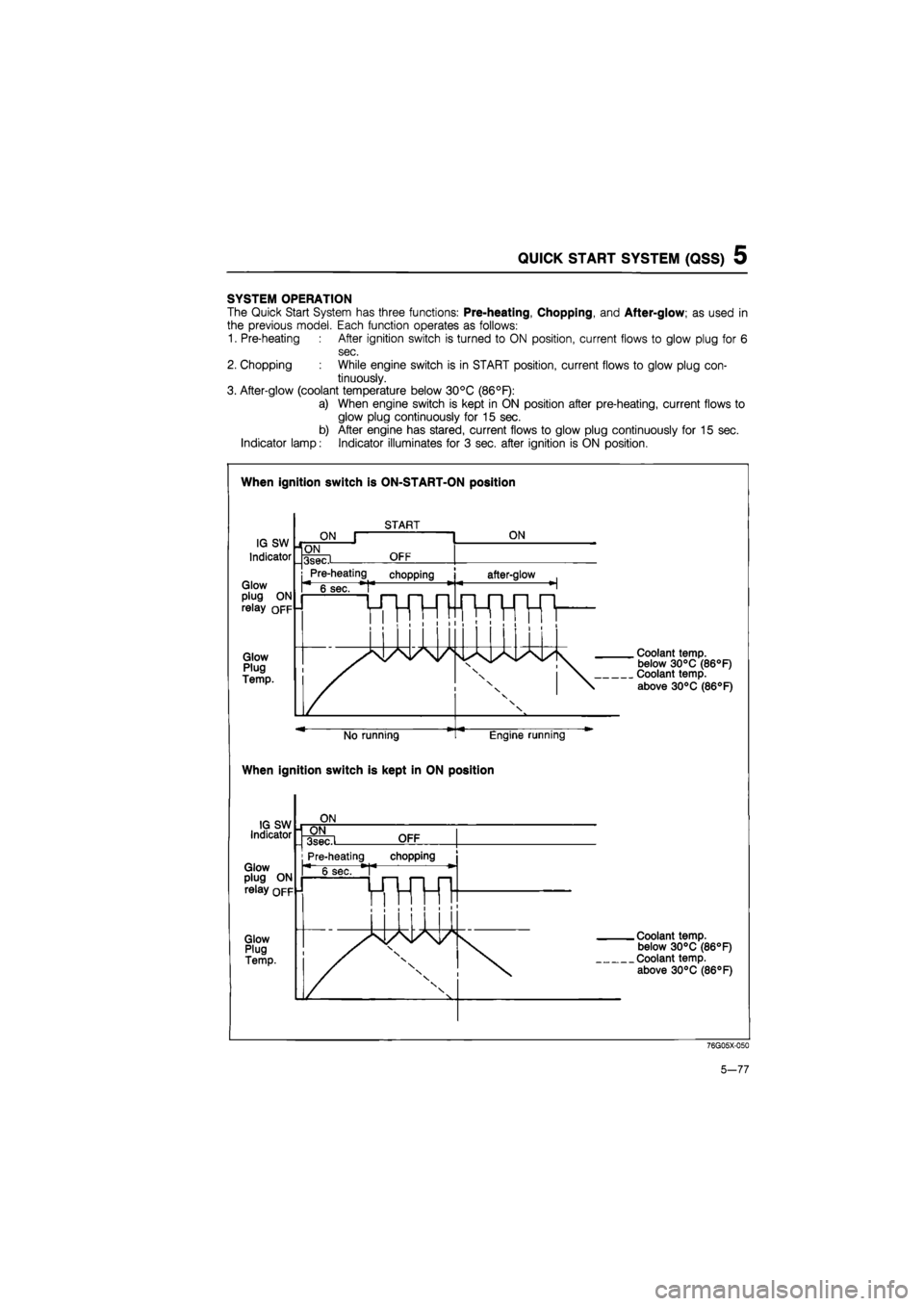
QUICK START SYSTEM (QSS) 5
SYSTEM OPERATION
The Quick Start System has three functions: Pre-heating, Chopping, and After-glow; as used in
the previous model. Each function operates as follows:
1. Pre-heating After ignition switch is turned to ON position, current flows to glow plug for 6
sec.
2. Chopping While engine switch is in START position, current flows to glow plug con-
tinuously.
3. After-glow (coolant temperature below 30°C (86°F):
a) When engine switch is kept in ON position after pre-heating, current flows to
glow plug continuously for 15 sec.
b) After engine has stared, current flows to glow plug continuously for 15 sec.
Indicator lamp: Indicator illuminates for 3 sec. after ignition is ON position.
When ignition switch is ON-START-ON position
When ignition switch is kept in ON position
76G05X-050
5-77
Page 880 of 1865

7B TROUBLESHOOTING (G4A-EL)
ON VEHICLE-
-f-
—OFF VEHICLE
\ Inspection point
and
\ reference page
Condition
•
Electronic control system Prelim-
inary
Hydraulic
control
system
Power train \ Inspection point
and
\ reference page
Condition
•
7B-66
m CO I m r--
7B-63
i
cn to I m
Section
4B
|
Section
4B
|
ID to i m
CO CO 1 CD
7B-68
|
en CO 1 IX)
to 1 00 r-.
cn CD 1 CO
7B-69
|
1 CD r--
cn s-1 m
Section
4B
r*-cn
S-1 CD h-
"=1-
rJ CO
7 CD r-
(XI o
1 m
cn CM 1 CD
7B-107
|
CD
7 CD 7 m
I
7B-113
I
CO CM
7 CO r-.
m cn
7 CO r-.
cn
7 DO r-
CM CM
7 CO
|
7B-126
CO
1*-r*-
7 m r-
\ Inspection point
and
\ reference page
Condition
•
Brake
light
switch
|
Inhibitor
switch
|
Mode
switch
|
1
CO. •o o X
Idle
switch
Throttle
sensor
|
Water
temp,
switch
|
0 tn c 0) cn
s
ffi
Q tn 01 o Hi >
Pulse
generator
|
"a o c 0) a to CM
TJ O CL ID s CO C\l 3-4
solenoid
|
Lock-up
solenoid
I
ATF
level
and
condition
|
Selector
lever
m Xj CO CJ 03
1 sz
Idle
speed
and
Ignition
timing
Control
valves
Accumulators
Oil
pump
Hydraulic
circuit
Torque
converter
Forward
clutch
Coasting
clutch
Reverse
clutch
JT O
u TT ro 2-4
brake
band
and
servo
$ 2
B cn cii > £ "O C CO
o
XI y
o >. CO S cb a O
One-way
clutch
2
s CI Cn tz JC 5 0-
Planetary
gear
Differential
assembly
Accelerating
Vehicle does
not
move
in
D,
S,
L,
or R
range
O O O O O O O O O O 0
Accelerating
Vehicle moves
in N
range -0 0 -—
Accelerating
Excessive creep
-0 O O -—
Accelerating
No creep
at all
O o o o
o
G 0 O O
Shifting
|
No shift
O O o
o
0 O 0 0
o
o O
Shifting
|
Abnormal shift sequence
0 o O O 0
o
o 0 O o o 0 O
Shifting
|
Frequent shifting 0 o 0 0 o 0 O O 0
Shifting
|
Excessively high
or
low
shift point 0 o 0 O 0 0 o 0 O 0 0
Shifting
|
No lock-up
0 o 0 0 o 0 O O o O
Shifting
|
No kick-down o o o o
Slipping
Engine
run
away
or
slip when
starting vehicle 0 o 0 O o O
Slipping
Engine
run
away
or
slip when
up-
or
down-shifting o o o 0 o O 0 0 O
8 n cn 4S SI V)
Excessive
N to D or N to R
shift shock o O o o o O
8 n cn 4S SI V)
Excessive shift shock when
up-
shifting
or
downshifting o o o o 0 0 0 8 n cn 4S SI V) Excessive shift shock when
changing range 0 0 o 0 o
j
Noise
Transaxle noisy
in N or P
range o o 0 O
j
Noise
Transaxle noisy
in D, S, L,
or
R range o 0 0 O
I
Others
j
No engine braking o O o 0 o o
I
Others
j
No mode change o 0 o o o o o o o
O
o
0
I
Others
j
Transaxle overheats
o o
0 o 0 o 0
I
Others
j
Vehicle moves
in
"P",
or
park-ing gear
not
disengaged when
"P"
is
dis-
engaged
0 O
I
Others
j
Hold indicator flashes o
0
o
0
o
O
o — — —
I
Others
j
Engine will
not
start
o
o
O — — —
76G07B-014
7B—14
Page 884 of 1865

7B TROUBLESHOOTING (G4A-EL)
Retrieval Procedure
1. Locate the service connector.
86U07B-019
76G07B-214
11 IDLFC
5» O | || KICK DOWNS* _ If, DEPRESS
|[BRAKE UORRSW
MNMWE STF *
° M CRUISE CONTROL SW
CDS®> *• PI ^ SPEED DROPS
Gf Aft
•
OO ou
I I
w
6019 HI NOW* XIKI
CO , LTQ
MUX
IN
JAP"
76G07B-016
2. Ground the ground connector of the EC-AT
Tester.
3. Connect the 6-pin connector of the EC-AT Tester
to the service connector.
Note
The service connector is blue-colored con-
nector.
4. Ground the 1 pin service connector.
Note
The service connector is blue-colored con-
nector.
5. Turn the ignition switch ON.
6. Check that "88" flashes on the digital display and
the buzzer sounds for three seconds after turning
the ignition switch ON.
7. If "88" does not flash, check the service connec-
tor wiring.
8. If "88" flashes and the buzzer sounds continuously
for more than 20 seconds, check wiring to 2M ter-
minal of the EC-AT control unit for short-circuit then
replace the EC-AT control unit and repeat steps
3 and 4.
9. Note the code numbers and check for the causes
by referring to the Inspection Procedure shown on
pages 7B—19 to 7B—21, repair as necessary.
Note
After repairs are made, recheck for code num-
bers by performing the "After-repair
procedure."
7B—18