ignition MAZDA 626 1987 Workshop Manual
[x] Cancel search | Manufacturer: MAZDA, Model Year: 1987, Model line: 626, Model: MAZDA 626 1987Pages: 1865, PDF Size: 94.35 MB
Page 885 of 1865

TROUBLESHOOTING (G4A-EL) 7B
79G07C-068
Drive at 50
km/h
(31
mph)
Kick-down
Stop
the
vehicle
79G07C-069
After-repair Procedure
1. Cancel the memory of malfunctions by disconnect-
ing the negative battery terminal for at least five sec-
onds, then reconnect it.
2. Remove the EC-AT tester if it is connected.
3. Drive the vehicle at 50 km/h (31 mph), then de-
press the accelerator pedal fully to activate kick-
down. Stop the vehicle gradually.
KICK goimsv
BRAKE LIGHTS*
CRUISE CONTROL
C V,. DEPRESS FULL*
Ox
azsa
ORUti rpn
"J
i"
•
rm uu
£ZL ofF
4. Reconnect the EC-AT tester to the 6-pin service
connector.
5. Ground the 1 -pin service connector with a jumper
wire.
6. Turn the ignition switch ON.
7. Check that no code numbers are displayed.
79G07C-070
Inspection Procedure
No. 06 code display (Vehicle speed sensor)
76G07B-017
7B-19
Page 890 of 1865

7B TROUBLESHOOTING (G4A-EL)
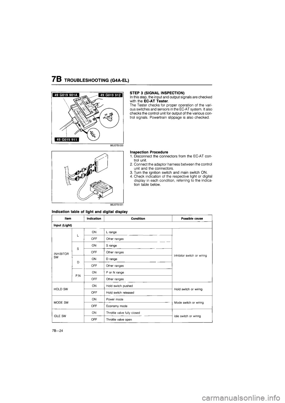
STEP 3 (SIGNAL INSPECTION)
In this step, the input and output signals are checked
with the EC-AT Tester.
The Tester checks for proper operation of the vari-
ous switches and sensors in the EC-AT system. It also
checks the control unit for output of the various con-
trol signals. Powertrain slippage is also checked.
Inspection Procedure
1. Disconnect the connectors from the EC-AT con-
trol unit.
2. Connect the adaptor harness between the control
unit and the connectors.
3. Turn the ignition switch and main switch ON.
4. Check indication of the respective light or digital
display in each condition, referring to the indica-
tion table below.
Indication table of light and digital display
Item Indication Condition Possible cause
Input (Light)
L ON L range L OFF Other ranges
S
ON S range
INHIBITOR
S OFF Other ranges Inhibitor switch or wiring SW
D ON D range
Inhibitor switch or wiring
D
OFF Other ranges
P,N
ON P or N range P,N OFF Other ranges
HOLD SW ON Hold switch pushed Hold switch or wiring HOLD SW
OFF Hold switch released
Hold switch or wiring
MODE SW ON Power mode Mode switch or wiring MODE SW
OFF Economy mode
Mode switch or wiring
IDLE SW ON Throttle valve fully closed Idle switch or wiring IDLE SW
OFF Throttle valve open
Idle switch or wiring
7B-24
Page 912 of 1865

7B TROUBLESHOOTING (G4A-HL)
5. Throttle Cable
(1) Check the inner and outer cable for damage.
(2) Make sure that the accelerator operates
smoothly.
76g07b-046
6. Idle Speed
Check idle speed. (Refer to Section 4A)
7. Tire Inflation Pressure
Check tire inflation pressure. (Refer to Section 12)
8. Ignition Timing
Check ignition timing. (Refer to Section 5)
7B-46
Page 929 of 1865

ELECTRICAL SYSTEM COMPONENTS 7B
Economy position
Power position • POWER
•ECONO
76G07B-066
86U07B-049
86U07B-050
ELECTRICAL
SYSTEM COMPONENTS
MODE SWITCH (G4A-EL)
Inspection of Operation
1. Turn the ignition switch ON.
2. Check that the mode indicator illuminates at each
model.
3. If it is not working properly, check terminal voltage
of mode switch.
Inspection of Continuity
1. Disconnect the mode switch.
2. Turn the ignition switch ON and light switch OFF.
3. Check the voltage between each terminal and
ground.
Mode Voltage Mode a b d e f
Power Approx. 12V
Below 1.5 V Below 1.5 V Below 1.5 V Below 1.5 V
Economy Below
1.5 V
Below
1.5 V Below 1.5 V
Below
1.5 V
Approx.
12V
4.
If
correct, check for continuty between the terminal.
Inspection of Terminal Voltage
1. Disconnect the mode switch connector.
2. Check continuity of the terminals.
Mode
Economy
Power
Connector terminal
O
O
f
o
-o
o
o
-o
-o
O—O: Indicates continuity
3. If not correct, replace the mode switch.
HOLD SWITCH (G4A-EL)
Inspection of Operation
1. Turn the ignition switch ON.
2. Check that the hold indicator illuminates while
switch depressed. Release the switch and mode
indicator lights are out.
3. If it is not working properly, check terminal voltage
of hold switch.
76G07B-067
7B—63
Page 930 of 1865

7B ELECTRICAL SYSTEM COMPONENTS
Inspection of Terminal Voltage
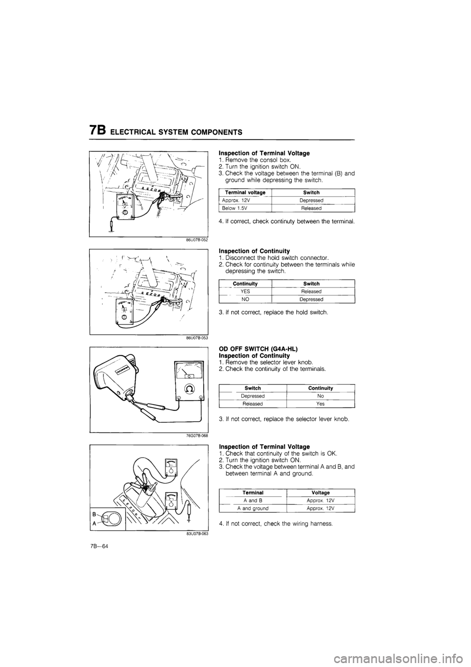
1. Remove the consol box.
2. Turn the ignition switch ON.
3. Check the voltage between the terminal (B) and
ground while depressing the switch.
Terminal voltage Switch
Approx. 12V Depressed
Below 1.5V Released
4. If correct, check continuty between the terminal.
86U07B-052
Inspection of Continuity
1. Disconnect the hold switch connector.
2. Check for continuity between the terminals while
depressing the switch.
Continuity Switch
YES Released
NO Depressed
3. If not correct, replace the hold switch.
86U07B-053
OD OFF SWITCH (G4A-HL)
Inspection of Continuity
1. Remove the selector lever knob.
2. Check the continuity of the terminals.
Switch Continuity
Depressed No
Released Yes
3. If not correct, replace the selector lever knob.
Inspection of Terminal Voltage
1. Check that continuity of the switch is OK.
2. Turn the ignition switch ON.
3. Check the voltage between terminal A and B, and
between terminal A and ground.
Terminal Voltage
A and B Approx. 12V
A and ground Approx. 12V
4. If not correct, check the wiring harness.
7B-64
Page 931 of 1865

ELECTRICAL SYSTEM COMPONENTS 7B
76G07B-069
76G07B-070
76G07B-071
INHIBITOR SWITCH
Inspection
1. Check that the starter turns with the ignition switch
at START position and the selector in the P and
N ranges, and dose not operate in other positions.
2. Check that the back-up (reverse) light illuminates
when shifted to the R range with the ignition switch
in the ON position.
3. Check the inhibitor switch if it is not working
properly.
Inspection of continuity
1. Disconnect the inhibitor switch connector.
2. Check continuity of the terminals.
G4A-EL
Position Connector terminal Position A B c D E F G H 1
P O-—O 0--O
R o--O
N o--o Pi N o--o
D o D U
S pi o S
L r o L
O—O: Indicates continuity
G4A-HL
Position Connector terminal Position a b c d
P 1 O— —O
O--o
N
D, 1, 2
O--O
O—O: indicates continuity
3. If not correct, replace switch and perform adjust-
ment of inhibitor switch.
Adjustment
1. Shift the selector lever to N range.
2. Loosen the inhibitor switch mounting bolts.
76G07B-072
7B—65
Page 932 of 1865

7B ELECTRICAL SYSTEM COMPONENTS
76G07B-073
7B-66
3. Remove the screw and move the inhibitor switch
so that the small hole is aligned with the screw hole.
4. Set the alignment by inserting a 2.0 mm (0.079
in) diameter pin through the holes.
5. Loosely tighten the switch mounting bolts, remove
the pin, and reinstall the screw.
6. Tighten the switch mounting bolts to specification.
Tightening torque:
8—11 N-m (80—110 cm-kg, 69—95 in-lb)
7. Recheck the continuity of the individual terminals.
WATER TEMPERATURE SWITCH
Inspection
1. Remove the water temperature switch.
2. Place the switch in water with a thermometer and
heat up the water gradually.
3. Check the continuity of the terminals. If necessary
replace the switch.
Connection guide
Water temperature Continuity
Below 65°C (149°F) Yes
Above 72°C (162°F) \ No
FLUID TEMPERATURE SWITCH (G4A-EL)
Inspection
1. Remove the fluid temperature switch.
2. Place the switch in oil with a thermometer as shown
and heat it up gradually.
3. Check the continuity of the terminals. If necessary
replace the switch.
Connection guide
Fluid temperature Continuity
Above 150°C (302°F) Yes
Below 143°C (289°F) No
BRAKE LIGHT SWITCH (G4A-EL)
Inspection of Terminal Voltage
1. Turn the ignition switch ON.
2. Check the voltage between terminal (WG) and
ground while depressing the brake pedal.
Terminal voltage I Brake pedal
Approx. 12V Depressed
Below 1,5V Released
3. If not correct, check continuity of the switch.
Page 933 of 1865

ELECTRICAL SYSTEM COMPONENTS 7B
Inspection of Continuity
1. Disconnect the brake light switch connector.
2. Check for continuity between the terminals while
depressing the brake pedal.
79G07C-114
76G07B-076
KICK-DOWN SWITCH (G4A-HL)
Inspection of Terminal Voltage
1. Turn the ignition switch ON.
2. Check the voltage at terminal (V) with a voltmeter.
Depressing stroke Terminal voltage
7/8-8/8 (Full) Approx. 12V
0-7/8 Below 1,5V
3. If not correct, check the wiring harness, switch, or
adjust the switch position.
Inspection of Continuty
1. Disconnect the kick-down switch connector.
2. Check for continuity of the switch with an
ohmmeter.
Switch Continuity
Pushed Yes
Released No
3. If not correct, replace the kick-down switch.
76G07B-077
Adjustment
1. Loosen the kick-down switch locknuts.
2. Depress the accelerator pedal fully.
3. Turn the switch until the threaded case touches the
stopper.
4. Turn the switch counterclockwise by one half revo-
lution.
5. Secure the switch with the locknut.
76G07B-078
7B—67
Page 934 of 1865

7B ELECTRICAL SYSTEM COMPONENTS
76G07B-079
76G07B-080
76G07B-081
PULSE GENERATOR (G4A-EL)
Inspection
1. Disconnect the pulse generator connector.
2. Check for continuity between the terminals, if
necessary replace the pulse generator.
Resistance: 200—400fl
VEHICLE SPEED SENSOR (G4A-EL)
Inspection of voltage
1. Connect a voltmeter between the 1Q terminal of
the EC-AT control unit and ground as shown.
2. Turn the ignition switch ON.
3. Remove the speedometer cable from the transaxle.
4. Slowly turn the speedometer cable one turn.
5. Check that approx. 4.5V is shown 4 times.
6. If not correct, check the combination meter.
CRUISE CONTROL SWITCH (CRUISE CONTROL
UNIT)
Refer to Section 15.
IDLE SWITCH AND THROTTLE SENSOR
(G4A-EL)
Refer to Section 4A.
OD RELEASE SOLENOID VALVE (G4A-HL)
Inspection of Resistance
1. Disconnect the solenoid valve connector.
2. Check resistance between the terminals.
Resistance: 13—27 ft
3. If not correct, replace the solenoid valve.
76G07B-082
7B-68
Page 936 of 1865

7B ELECTRICAL SYSTEM COMPONENTS
Terminal Connected to Voltage Condition
1J — — —
1K — — —
1L (Input) Idle switch Below 1.5V At idle 1L (Input) Idle switch Approx. 12V Other speeds
1M — — —
1N (Input) Brake light switch Approx. 12V Brake pedal depressed 1N (Input) Brake light switch Below 1.5V Brake pedal released
10 (Input) Throttle sensor
Approx. 5V Ignition switch ON 10 (Input) Throttle sensor Below 1,5V Ignition switch OFF
1P (Input)
Throttle sensor
Approx. 0.5—4.3V Throttle valve fully closed to fully open
1Q (Input) Vehicle speed sensor
Approx. 4.5V During driving
1Q (Input) Vehicle speed sensor Approx. 4.5V or below 1.5V Vehicle stopped
1R (Ground) Throttle sensor Below 1,5V —
1S (Input) Pulse generator Approx. 12V Engine running 1S (Input) Pulse generator Below 1,5V Engine stopped
1S (Ground) Pluse generator Below 1.5V —
2A (Battery power) Battery Approx. 12V Ignition switch ON 2A (Battery power) Battery Below 1,5V Ignition switch OFF
2B (Ground) Body ground Below 1,5V —
2C (Memory power) Battery Approx. 12V —
2D (Ground) Body ground Below 1,5V —
2E (Output) 1-2 shift solenoid valve Approx. 12V
Refer to page 7B—26 of solenoid valve
operation table
2E (Output) 1-2 shift solenoid valve Below 1.5V Refer to page 7B—26 of solenoid valve
operation table
2F (Output) 2-3 shift solenoid valve Approx. 12V
Refer to page 7B—26 of solenoid valve
operation table
2F (Output) 2-3 shift solenoid valve Below 1,5V
Refer to page 7B—26 of solenoid valve
operation table
2G — — —
2H (Output) 3-4 shift solenoid valve Approx. 12V Refer to page 7B—26 of solenoid valve operation table 2H (Output) 3-4 shift solenoid valve Below 1.5V
Refer to page 7B—26 of solenoid valve operation table
21 — — —
2J (Output) Lock-up solenoid valve Approx. 12V Lock-up 2J (Output) Lock-up solenoid valve Below 1,5V Other
2K (Output) Hold indicator Below 1,5V Hold mode 2K (Output) Hold indicator Approx. 12V Other modes
2L (Output) Mode indicator Approx. 12V Hold mode 2L (Output) Mode indicator Below 1,5V Power or economy mode
2M (Output) EC-AT Tester
(malfunction code)
Approx. 12V Normal
2M (Output) EC-AT Tester
(malfunction code) Below 1,5V If malfunction present 2M (Output) EC-AT Tester
(malfunction code) Code signal Self-diagnosis check connector grounded
2N — — —
20 (Input) Fluid temperature switch Below 1,5V Above 150°C (302°F) 20 (Input) Fluid temperature switch Approx. 10—12V Below 143°C (289°F)
2P (Input) EC-AT check connect Approx. 12V —
76G07B-084
7B-70