MAZDA 626 1987 Workshop Manual
Manufacturer: MAZDA, Model Year: 1987,
Model line: 626,
Model: MAZDA 626 1987
Pages: 1865, PDF Size: 94.35 MB
MAZDA 626 1987 Workshop Manual
626 1987
MAZDA
MAZDA
https://www.carmanualsonline.info/img/28/57059/w960_57059-0.png
MAZDA 626 1987 Workshop Manual
Trending: seat adjustment, oil, fuel pump, roof, tires, wheel torque, service
Page 1691 of 1865
1 5 WARNING LIGHT AND SENDER
76G15X-042
Low Fuel Level Warning Light
does not illuminate
Replace the fuel gauge unit
86U15X-060
86U15X-061
15-36
Page 1692 of 1865
WARNING LIGHT AND SENDER 1 5
76G15X-090
Seat Belt Warning Light
76G15X-043
EC-AT Mode Indicator Light
POWER and ECONO indicator lights
do
not
il-
luminate.
NG
Check the hold switch. Refer
to
page 7B—63
NG
Replace the switch.
OK
NG
Check the mode switch. Refer
to
page 7B—63
NG
Replace the switch.
fOK
Replace the bulb
or
repair the harness (Meter
to
mode switch, EC-AT switch
to
control unit).
76G15X-091
76G15X-044
15—37
Page 1693 of 1865
1 5 WARNING AND SENDER
Shift Indicator Light
All shift indicator lights do not Illuminate when ignition switch on. (other warning light are all right.)
Check the voltage
at BY
terminal
of
the inhibitor switch connector with ignition switch
on.
Terminal Voltage
BY 12V
NG
Repair the harness (Fuse box
to
inhibitor switch).
OK
Check the inhibitor switch. Refer
to
page 7B—65
NG
Replace the inhibitor switch. Check the inhibitor switch. Refer
to
page 7B—65 Replace the inhibitor switch.
OK
NG
Check the bulbs
of
the shift indicator lights.
NG
Replace the bulb.
OK
Turn the ignition switch on, and check the voltage
at
each terminal
of
the meter connector with each con-dition.
Terminal Selector lever Voltage
YL (2J) P 12V
RG (1L) R 12V
YR (2L) N 12V
Y(1V) D 12V
YB (1S) 2 12V
YW (1M) 1 12V
NG
Repair the harness (Inhibitor switch
to
meter).
76G15X-087
O/D OFF Indicator Light
OK
Repair the harness (O/D OFF switch
to
ground).
76G15X092
15-38
Page 1694 of 1865
WARNING AND SENDER 15
Coolant Level Warning Light
OK
Repair harness (Meter
to
coolant level sensor).
76G15X093
INSPECTION
Brake Fluid Level Sensor
1. Check for continuity of the sensor with an
ohmmeter.
Float level Continuity
Below
min
Yes
Above
min
No
2. If continuity is not as specified, replace the sensor.
86U15X-065
86U14X-066
Parking Brake Switch
1. Check for continuity between (R) terminal and a
body ground with an ohmmeter.
Lever Continuity
Pulled one notch Yes
Released No
2. If continuity is not as specified, adjust the switch
or replace the switch.
15—39
Page 1695 of 1865
15 WARNING AND SENDER
86U15X-068
86U15X069
86U15X-070
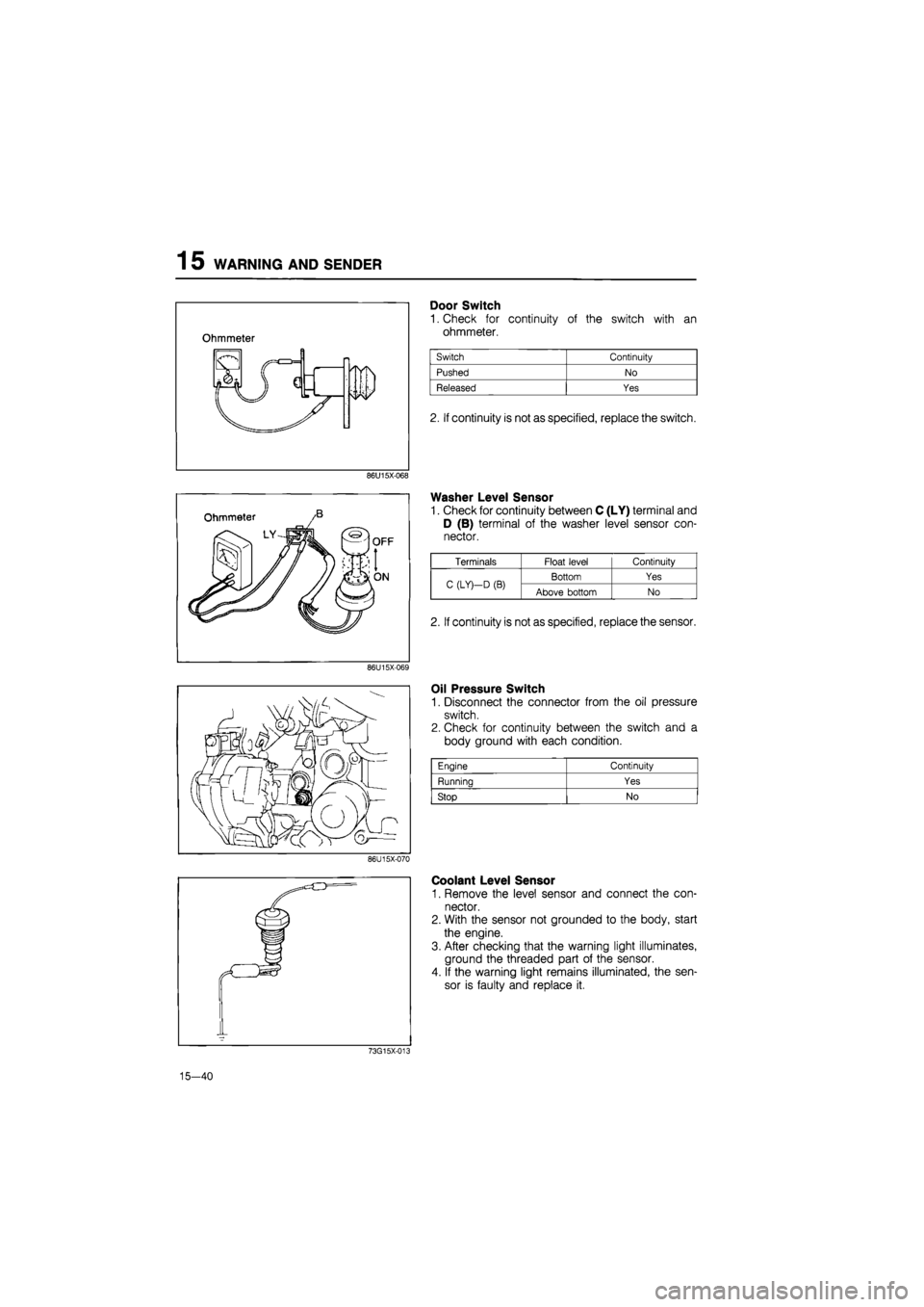
Door Switch
1. Check for continuity of the switch with an
ohmmeter.
2. If continuity is not as specified, replace the switch.
Washer Level Sensor
1. Check for continuity between C (LY) terminal and
D (B) terminal of the washer level sensor con-
nector.
Oil Pressure Switch
1. Disconnect the connector from the oil pressure
switch.
2. Check for continuity between the switch and a
body ground with each condition.
Coolant Level Sensor
1. Remove the level sensor and connect the con-
nector.
2. With the sensor not grounded to the body, start
the engine.
3. After checking that the warning light illuminates,
ground the threaded part of the sensor.
4. If the warning light remains illuminated, the sen-
sor is faulty and replace it.
73G15X-013
15—40
Engine Continuity
Running Yes
Stop No
Terminals Float level Continuity
C (LY)—D
(B)
Bottom Yes C (LY)—D
(B)
Above bottom No
2. If continuity is not as specified, replace the sensor.
Page 1696 of 1865
CENTRAL PROCESSING UNIT (CPU) 1 5
CENTRAL PROCESSING UNIT (CPU)
STRUCTURAL VIEW
86U15X-071
FUNCTIONS
System Function
Sound Alarm System
Key reminder alarm
Sound Alarm System
Liaht-off reminder alarm
Sound Alarm System
Seat belt alarm
Timer System
Seat belt timer
Timer System
Kev illumination liaht timer
Timer System
Interior light timer
76G15X-008
15—41
Page 1697 of 1865
1 5 CENTRAL PROCESSING UNIT (CPU)
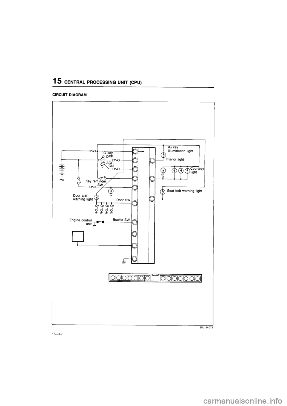
CIRCUIT DIAGRAM
-O-vO
I &
IG key
OFF
n\ Key reminder
Door ajar
warning light vf Door SW
llfl Engine control —_
unitj^"
Buckle SW
W7i
0
o
o
0
o
0
o
o
o
a
Q
u
n
dD
IG key
illumination light
[ Interior light
(f)
(f) (|)
teesy
J
cF Seat belt warning light
o o o 0 o o o
•a-
o o o o o o o
15-42
86U15X-073
Page 1698 of 1865

CENTRAL PROCESSING UNIT (CPU) 1 5
REMOVAL AND INSTALLATION
1. Disconnect the negative battery cable.
2. Disconnect the CPU connectors.
3. Release the lock and remove the CPU from the
joint box.
4. Install in the reverse order of removal.
ON-VEHICLE INSPECTION
Note: Check the voltage between "a through
I" terminal and ground.
Check the continuity between "m,
n" terminal and ground.
86U15X-075
Terminal Connecting
to
Measurement condition Measurement value
a Interior light and courtesy lights Any time Approx.
12V
b Batterv Anv time Approx.
12V
c No used
— —
d Ground Anv time OV
e Seat belt warning light Ignition switch
ON
Approx.
12V
f Enaine control unit Enaine runnina Approx.
12V
g Key cylinder illumination light Any time Approx.
12V
i Key reminder switch Insert the key into the cylinder
Pull out the key from the cylinder
Approx.
12V
OV
j Ignition switch (ON) Ignition switch
ON
Ignition switch OFF
or
ACC
Approx.
12V
OV
k Ignition switch (ACC) Ignition switch
ON or
ACC
Ignition switch OFF
Approx.
12V
OV
I Light switch (In the combination switch) Turn the light switch ACC and
ON
Light switch OFF
Approx.
12V
OV
m Seat belt switch Seat belt fastened
Seat belt unfastered
OQ
OO
n Door switch Door closed
Door open
OO
on
76G15X-009
15—43
Page 1699 of 1865
1 5 TURN AND HAZARD LIGHT
TURN AND HAZARD LIGHT
STRUCTURAL VIEW
86U15X-077
15—44
Page 1700 of 1865
TURN AND HAZARD LIGHT 1 5
CIRCUIT DIAGRAM
86U15X-078
15—45
Trending: lights, width, radio, fuses, oil, child lock, belt


