fuse MAZDA 626 1987 Workshop Manual
[x] Cancel search | Manufacturer: MAZDA, Model Year: 1987, Model line: 626, Model: MAZDA 626 1987Pages: 1865, PDF Size: 94.35 MB
Page 14 of 1865

0 PRE-DELIVERY INSPECTION
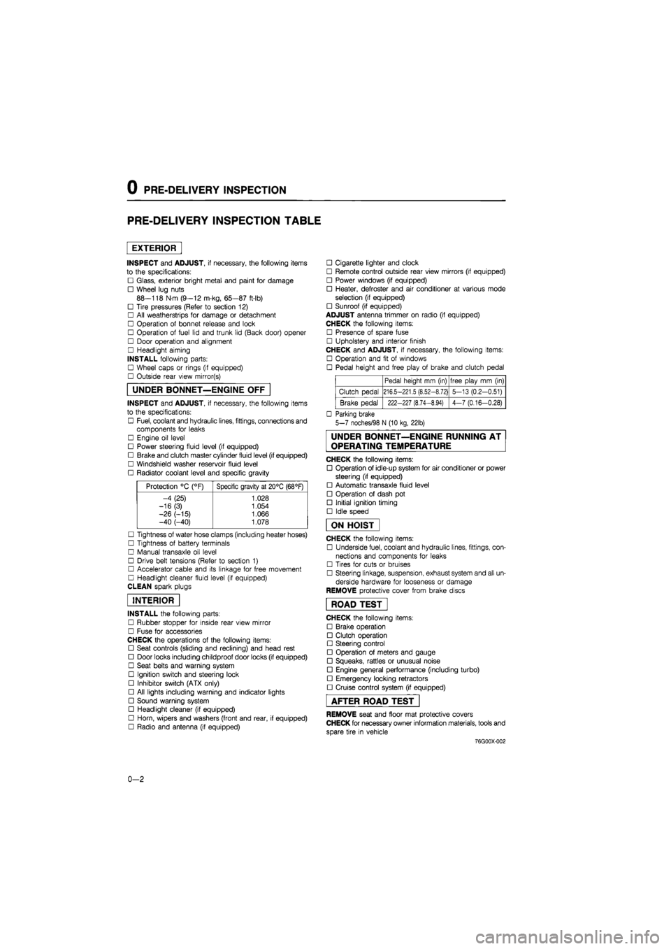
PRE-DELIVERY INSPECTION TABLE
EXTERIOR
INSPECT and ADJUST, if necessary, the following items
to the specifications:
• Glass, exterior bright metal and paint for damage
• Wheel lug nuts
88—118 N m (9—12 m-kg, 65—87 ft-lb)
• Tire pressures (Refer to section 12)
• All weatherstrips for damage or detachment
• Operation of bonnet release and lock
• Operation of fuel lid and trunk lid (Back door) opener
• Door operation and alignment
• Headlight aiming
INSTALL following parts:
• Wheel caps or rings (if equipped)
• Outside rear view mirror(s)
UNDER BONNET—ENGINE OFF
INSPECT and ADJUST, if necessary, the following items
to the specifications:
• Fuel, coolant and hydraulic lines, fittings, connections and
components for leaks
• Engine oil level
• Power steering fluid level (if equipped)
• Brake and clutch master cylinder fluid level (if equipped)
• Windshield washer reservoir fluid level
• Radiator coolant level and specific gravity
Protection °C (°F) Specific gravity at 20°C (68°F)
-4 (25) 1.028
-16(3) 1.054
-26 (-15) 1.066 -40 (-40) 1.078
• Tightness of water hose clamps (including heater hoses)
• Tightness of battery terminals
• Manual transaxle oil level
• Drive belt tensions (Refer to section 1)
• Accelerator cable and its linkage for free movement
• Headlight cleaner fluid level (if equipped)
CLEAN spark plugs
INTERIOR
INSTALL the following parts:
• Rubber stopper for inside rear view mirror
• Fuse for accessories
CHECK the operations of the following items:
• Seat controls (sliding and reclining) and head rest
• Door locks including childproof door locks (if equipped)
• Seat belts and warning system
• Ignition switch and steering lock
• Inhibitor switch (ATX only)
• All lights including warning and indicator lights
• Sound warning system
• Headlight cleaner (if equipped)
• Horn, wipers and washers (front and rear, if equipped)
• Radio and antenna (if equipped)
• Cigarette lighter and clock
• Remote control outside rear view mirrors (if equipped)
• Power windows (if equipped)
• Heater, defroster and air conditioner at various mode
selection (if equipped)
• Sunroof (if equipped)
ADJUST antenna trimmer on radio (if equipped)
CHECK the following items:
• Presence of spare fuse
• Upholstery and interior finish
CHECK and ADJUST, if necessary, the following items:
• Operation and fit of windows
• Pedal height and free play of brake and clutch pedal
Pedal height mm (in) free play mm (in)
Clutch pedal 216.5-221.5 (8.52-8.72) 5-13 (0.2-0.51)
Brake pedal 222-227 (8.74-8.94) 4-7 (0.16-0.28)
• Parking brake
5-7 noches/98 N (10 kg, 22lb)
UNDER BONNET—ENGINE RUNNING AT
OPERATING TEMPERATURE
CHECK the following items:
• Operation of idle-up system for air conditioner or power
steering (if equipped)
• Automatic transaxle fluid level
• Operation of dash pot
• Initial ignition timing
• Idle speed
ON HOIST
CHECK the following items:
• Underside fuel, coolant and hydraulic lines, fittings, con-
nections and components for leaks
• Tires for cuts or bruises
• Steering linkage, suspension, exhaust system and all un-
derside hardware for looseness or damage
REMOVE protective cover from brake discs
ROAD TEST"
CHECK the following items:
• Brake operation
• Clutch operation
• Steering control
• Operation of meters and gauge
• Squeaks, rattles or unusual noise
• Engine general performance (including turbo)
• Emergency locking retractors
• Cruise control system (if equipped)
AFTER ROAD TEST
REMOVE seat and floor mat protective covers
CHECK for necessary owner information materials, tools and
spare tire in vehicle
-76G00X-002
0-2
Page 130 of 1865

1A INSTALLATION
76G01A-147
86U01X-199
86U01X-200
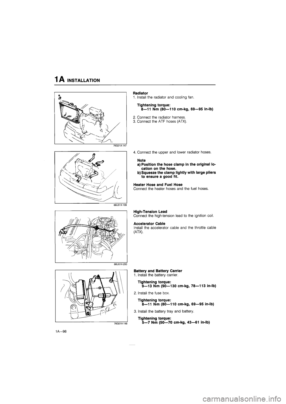
Radiator
1. Install the radiator and cooling fan.
Tightening torque:
8—11 N-m (80—110 cm-kg, 69—95 in-lb)
2. Connect the radiator harness.
3. Connect the ATF hoses (ATX).
4. Connect the upper and lower radiator hoses.
Note
a) Position the hose clamp in the original lo-
cation on the hose.
b) Squeeze the clamp lightly with large pliers
to ensure a good fit.
Heater Hose and Fuel Hose
Connect the heater hoses and the fuel hoses.
High-Tension Lead
Connect the high-tension lead to the ignition coil.
Accelerator Cable
Install the accelerator cable and the throttle cable
(ATX).
76G01A-148
Battery and Battery Carrier
1. Install the battery carrier.
Tightening torque:
9—13 N-m (90—130 cm-kg, 78—113 in-lb)
2. Install the fuse box.
Tightening torque:
8—11 N-m (80—110 cm-kg, 69—95 in-lb)
3. Install the battery tray and battery.
Tightening torque:
5_7 Nm (50—70 cm-kg, 43—61 in-lb)
1A—98
Page 211 of 1865

1B INSTALLATION
76G01B-113
76G01B-114
76G01B-115
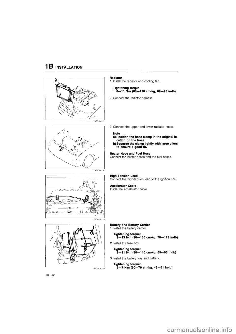
Radiator
1. Install the radiator and cooling fan.
Tightening torque:
8—11 N-m (80—110 cm-kg, 69—95 in-lb)
2. Connect the radiator harness.
3. Connect the upper and lower radiator hoses.
Note
a) Position the hose clamp in the original lo-
cation on the hose.
b) Squeeze the clamp lightly with large pliers
to ensure a good fit.
Heater Hose and Fuel Hose
Connect the heater hoses and the fuel hoses.
High-Tension Lead
Connect the high-tension lead to the ignition coil.
Accelerator Cable
Install the accelerator cable.
76G01A-148
Battery and Battery Carrier
1. Install the battery carrier.
Tightening torque:
9—13 N-m (90—130 cm-kg, 78—113 in-lb)
2. Install the fuse box.
Tightening torque:
8—11
N
m (80—110 cm-kg, 69—95 in-lb)
3. Install the battery tray and battery.
Tightening torque:
5_7
N m
(50—70 cm-kg, 43—61 in-lb)
1B—80
Page 351 of 1865

3A COOLING FAN
COOLING FAN
SYSTEM CIRCUIT
IG1 IG Relay
*
No.1
relay
Water thermo switch
I With A/C
CM)
Main fan
1
L..±
No.2
relay
IG2
Add.
relay ol
(M)
A/C sw.
Add fan
86U03X-019
CIRCUIT INSPECTION
1. Turn the ignition switch ON.
2. Disconnect the water thermo switch connector, and
check that the fan operates.
3. If the fan doesn't operate, check the fuse, fan re-
lay, fan motor, thermo switch and wiring harness.
76G03A-010
3 A—12
Page 363 of 1865

3B COOLING FAN
COOLING FAN
SYSTEM CIRCUIT
I
IG1 IG Relay Main fuse
©
Main fan motor
V-f motor
IG1
Water thermo switch OFF: over 91°C (208 °F)
Water thermo switch ON:
below 84°C
(183°F)
76G03B-015
CIRCUIT INSPECTION
1. Turn the ignition switch ON.
2. Disconnect the water thermo switch connector, and
check that the fan begins to operate.
3. If the fan doesn't operate, check the fuse, fan re-
lay, fan motor, thermo switch, and wiring harness.
76G03B-016
3B—10
Page 382 of 1865

TROUBLESHOOTING GUIDE
4A
TROUBLESHOOTING GUIDE
F6 (GENERAL)
The Troubleshooting Guide lists the systems most likely to cause
a
given symptom. After finding the
system(s)
to
check, refer
to
the pages shown
for
detailed guides
for
each system.
\\ POSSIBLE CAUSE
\ PAGE
SYMPTOM
Air
cleaner
(Air
cleaner
element)
intake
air
temperature
control
system
Idle
adjustment
Fuel
system
(Carburetor,
Fuel
pump)
idle-up
control
system
Exhaust
system
Positive
crankcase
ventilation
system
Auto-return
choke
system
\\ POSSIBLE CAUSE
\ PAGE
SYMPTOM 4A—23 4A—60 4A—38 4A—24 4A—68 4A—96 4A—67 4A—40
1 Hard start
or
won't start (Cranks
OK)
1 2
2 Engine stalls During warm
up
3 2 1 4
2 Engine stalls After warm
up
4 2 5 1 3
3 Rough Idle During warm
up
3 2 1 4
3 Rough Idle After warm
up
3 2 5 1 4
4 High idle speed after warm
up
1 3 2
5 Poor acceleration, hesitation, or lack
of
power
1 2 3
6 Runs rough
on
deceleration
1
7 Afterburn
in
exhaust system
1
8 Poor fuel consumption
2 1 4 3
9 Fails emission test
2 1 4 5 3
76G04A-015
The numbers of the list show the priorities
of
inspections from the most possible to that with the lowest
possibility.
These were determined
on
the following basis:
• Ease
of
inspection
•
Most possible system
•
Most Possible point
in
system
TROUBLESHOOTING PROCEDURE:
1st Check the following items:
Electrical system
1) Battery condition
2) Fuses
Ignition system
1) Spark plugs
2) Ignition timing
Fuel system
1) Fuel level
2) Fuel leakage
3) Fuel filter
4) Idle speed
Intake
air
system
1) Vacuum
or air
leakage
2) Vacuum hose routing
3) Accelerator cable
4) Choke cable
2nd Check Fuel and Emission Control Systems
Engine
1) Compression
2) Overheating
Others
1) Clutch slippage
2) Brake dragging
4 A-17
Page 383 of 1865

4A TROUBLESHOOTING GUIDE
F6 (SINGAPORE)
The Troubleshooting Guide lists the systems most likely
to
cause
a
given symptom. After finding
the
system(s)
to
check, refer
to the
pages shown
for
detailed guides
for
each system.
POSSIBLE CAUSE
\ PAGE
SYMPTOM
Air
cleaner
(Air
cleaner
element)
Intake
air
temperature
control
system
Idle
adjustment
Fuel
system
(Carburetor,
Fuel
pump)
Air
injection
system
Deceleration
control
system
Positive
crankcase
ventilation
system
Exhaust
system
Idle-up
control
system
POSSIBLE CAUSE
\ PAGE
SYMPTOM 4A-23 4A-60 4 A—38 4A—24 4A-58 4A-45 4A-67 4A-SW 4A—68
1 Hard start
or
won't start (Cranks
OK)
1 2
2 Engine stalls During warm
up
3 2 1 4
2 Engine stalls After warm
up
3 2 4 1
3 Rough idle During warm
up
3 2 1 4
3 Rough idle After warm
up
3 2 4 1
4 High idle speed after warm
up
1 4 3* 2
5 Poor acceleration, hesitation,
or
lack
of
power
1 2 3
6 Runs rouah
on
deceleration
2 1
7 Afterburn
in
exhaust svstem
2 1
8 Poor fuel consumption
2 1 4 3
9 Fails emission test
6 4 5 3 2 1
Only MTX
76G04A-016
The numbers
of
the list show the priorities
of
inspections from the most possible to that with the lowest
possibility.
These were determined
on the
following basis:
• Ease
of
inspection
•
Most possible system
•
Most possible point
in
system
TROUBLESHOOTING PROCEDURE:
1st Check
the
following items:
Electrical system
1) Battery condition
2) Fuses
Ignition system
1) Spark plugs
2) Ignition timing
Fuel system
1) Fuel level
2) Fuel leakage
3) Fuel filter
4) Idle speed
Intake
air
system
1) Vacuum
or air
leakage
2) Vacuum hose routing
3) Accelerator cable
Engine
1) Compression
2) Overheating
Others
1) Clutch slippage
2) Brake dragging
2nd Check
the
Fuel
and
Emission Control Systems
4A—18
Page 384 of 1865

TROUBLESHOOTING GUIDE
4A
FE
12
VALVE and
F8
(EXCEPT MIDDLE EAST and GENERAL)
The Troubleshooting Guide lists the systems most likely to cause
a
given symptom. After finding
the
system(s)
to
check, refer
to
the pages shown
for
detailed guides
for
each system.
POSSIBLE CAUSE
\ PAGE
SYMPTOM
Air
cleaner
(Air
cleaner
element)
Intake
air
temperature
control
system
Idle
adjustment
Fuel
system
(Carburetor,
Fuel
pump)
PTC
heater
system
Air
injection
system
Positive
crankcase
ventilation
system
Deceleration
control
system
Idle-up
control
system
Ignition
control
system
POSSIBLE CAUSE
\ PAGE
SYMPTOM
4A-23 4A-60 4A-38 4A-24 4A-42 4A-58 4A-67 4A—45 4A—68 4 A—80
1 Hard start
or
won't start
(Cranks
OK)
1 2
2 Engine stalls During warm
up
5 4 1 6 2 3
2 Engine stalls After warm
up
3 2 4 1
3 Rough idle During warm
up
5 4 1 6 2 3
3 Rough idle After warm
up
3 2 4 1
4 High idle speed after warm
up
1 4 3 2
5 Poor acceleration, hesitation, or lack
of
power
1 4 2 3
6 Runs rough
on
deceleration
2 1
7 Afterburn
in
exhaust system
2 1
8 Poor fuel consumption
3 1 4 2
4
9 Fails emission test
6 2 5 3 1 4
76G04A-017
The numbers of the list show the priorities
of
inspections from the most possible to that with the lowest
possibility.
These were determined
on the
following basis:
• Ease
of
inspection
•
Most possible system
•
Most possible point
in
system
TROUBLESHOOTING PROCEDURE:
1st Check the following items:
Electrical system
1) Battery condition
2) Fuses
Ignition system
1) Spark plugs
2) Ignition timing
Fuel system
1) Fuel level
2) Fuel leakage
3) Fuel filter
4) Idle speed
Intake
air
system
1) Vacuum
or air
leakage
2) Vacuum hose routing
3) Accelerator cable
Engine
1) Compression
2) Overheating
Others
1) Clutch slippage
2) Brake dragging
2nd Check the Fuel
and
Emission Control Systems
4A—19
Page 385 of 1865

4A TROUBLESHOOTING GUIDE
FE and F8 (GENERAL)
The Troubleshooting Guide lists the systems most likely to cause a given symptom. After finding the
system(s) to check, refer to the pages shown for detailed guides for each system.
POSSIBLE CAUSE
\ PAGE
SYMPTOM
Air
cleaner
(Air
cleaner
element)
Intake
air
temperature
control
system
Idle
adjustment
Fuel
system
(Carburetor,
Fuel
pump)
Idle-up
control
system
PTC
heater
system
Positive
crankcase
ventilation
system
Deceleration
control
system
POSSIBLE CAUSE
\ PAGE
SYMPTOM 4A-23 4A—60 4A—38 4A—24 4A—68 4A—42 4A—67 4A—45
1 Hard start or won't start (Cranks OK) 1 2
2 Engine stalls During warm up 5 4 1 6 2 3 2 Engine stalls After warm up 3 2 4 1
3 Rough idle During warm up 5 4 1 6 2 3 3 Rough idle After warm up 3 2 4 1
4 High idle speed after warm up 1 4 2 3
5 Poor acceleration, hesitation, or lack of power 1 4 3 2
6 Runs rough on deceleration 2 1
7 Afterburn in exhaust system 2 1
8 Poor fuel consumption 2 1 3
9 Fails emission test 3 2 4 1
76G04A-018
The numbers of the list show the priorities of inspections from the most possible to that with the lowest
possibility.
These were determined on the following basis:
Ease of inspection Most possible system Most possible point in system
TROUBLESHOOTING PROCEDURE:
1st Check the following items:
Electrical system
1) Battery condition
2) Fuses
Ignition system
1) Spark plugs
2) Ignition timing
Fuel system
1) Fuel level
2) Fuel leakage
3) Fuel filter
4) Idle speed
Intake air system
1) Vacuum or air leakage
2) Vacuum hose routing
3) Accelerator cable
Engine
1) Compression
2) Overheating
Others
1) Clutch slippage
2) Brake dragging
2nd Check the Fuel and Emission Control Systems
4A—20
Page 386 of 1865

TROUBLESHOOTING GUIDE 4A
FE (MIDDLE EAST)
The Troubleshooting Guide lists the systems most likely to cause a given symptom. After finding the
system(s) to check, refer to pages shown for detailed guides for each system.
V. POSSIBLE CAUSE
\ PAGE
SYMPTOM
I
Air
cleaner
(Air
cleaner
element)
Intake
air
temperature
control
system
Idle
adjustment
Fuel
system
(Carburetor,
Fuel
pump)
Idle-up
control
system
Dashpot
(Only
MTX)
Positive
crankcase
ventilation
system
Exhaust
system
Evaporative
emission
control
system
Auto-return
choke
system
V. POSSIBLE CAUSE
\ PAGE
SYMPTOM 4A—23 4A-60 4 A—38 4A-24 4A-68 4A-50 4A-67 4A-96 4A-78 4A-40
1 Hard start or won't start
(Cranks OK) 1 2 3
2 Engine stalls During warm up 3 2 1 4 2 Engine stalls After warm up 3 2 4 1
3 Rough idle During warm up 3 2 1 4 3 Rough idle After warm up 3 2 4 1
4 High idle speed after warm up 1 5 3 4 2
5 Poor acceleration, hesitation, or lack of power 1 2 3
6 Runs rough on deceleration 2 1
7 Afterburn in exhaust system 3 1 2
8 Poor fuel consumption 5 1 6 2 3 4
9 Falls emission test 5 4 6 3 1 2
76G04A-019
The numbers of the list show the priorities of inspections from the most possible to that with the lowest
possibility.
These were determined on the following basis:
• Ease of inspection • Most possible system • Most possible point in system
TROUBLESHOOTING PROCEDURE:
1st Check the following items:
Electrical system
1) Battery condition
2) Fuses
Ignition system
1) Spark plugs
2) Ignition timing
Fuel system
1) Fuel level
2) Fuel leakage
3) Fuel filter
4) Idle speed
Intake air system
1) Vacuum or air leakage
2) Vacuum hose routing
3) Accelerator cable
4) Choke cable
Engine
1) Compression
2) Overheating
Others
1) Clutch slippage
2) Brake dragging
2nd Check the Fuel and Emission Control Systems
4 A—21