check engine MAZDA 626 1987 Workshop Manual
[x] Cancel search | Manufacturer: MAZDA, Model Year: 1987, Model line: 626, Model: MAZDA 626 1987Pages: 1865, PDF Size: 94.35 MB
Page 778 of 1865
5 STARTER (DIESEL ENGINE, 2.2 KW TYPE)
4BG05X-115
4BG05X-085
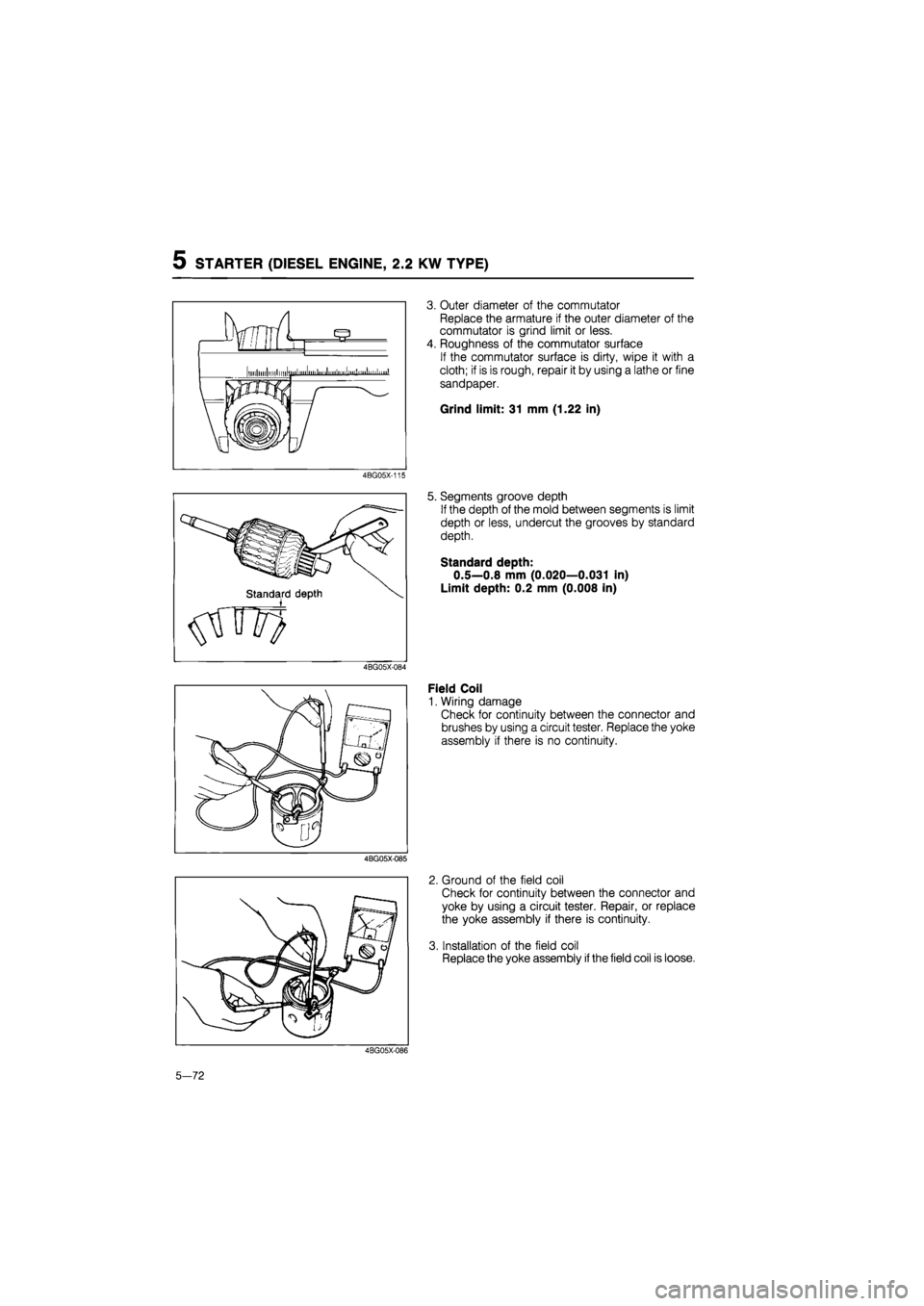
3. Outer diameter of the commutator
Replace the armature if the outer diameter of the
commutator is grind limit or less.
4. Roughness of the commutator surface
If the commutator surface is dirty, wipe it with a
cloth; if is is rough, repair it by using a lathe or fine
sandpaper.
Grind limit: 31 mm (1.22 in)
5. Segments groove depth
If the depth of the mold between segments is limit
depth or less, undercut the grooves by standard
depth.
Standard depth:
0.5—0.8 mm (0.020—0.031 in)
Limit depth: 0.2 mm (0.008 in)
Field Coil
1. Wiring damage
Check for continuity between the connector and
brushes by using a circuit tester. Replace the yoke
assembly if there is no continuity.
2. Ground of the field coil
Check for continuity between the connector and
yoke by using a circuit tester. Repair, or replace
the yoke assembly if there is continuity.
3. Installation of the field coil
Replace the yoke assembly
if
the field coil is loose.
4BG05X-086
5-72
Page 779 of 1865
STATRER (DIESEL ENGINE, 2.2 KW TYPE) 5
11*mm S (0.433 in)
A
A 18 mm
(0,709)
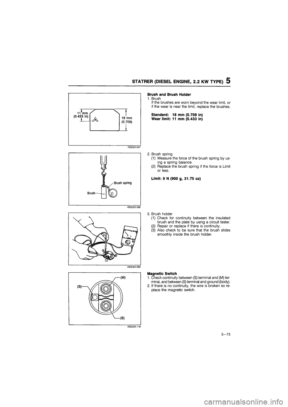
Brush and Brush Holder
1. Brush
If the brushes are worn beyond the wear limit, or
if the wear is near the limit, replace the brushes.
Standard: 18 mm (0.709 in)
Wear limit: 11 mm (0.433 in)
76G05X-047
2. Brush spring
(1) Measure the force of the brush spring by us-
ing a spring balance.
(2) Replace the brush spring if the force is Limit
or less.
Limit: 9 N (900 g, 31.75 oz)
4BG05X-088
3. Brush holder
(1) Check for continuity between the insulated
brush and the plate by using a circuit tester.
(2) Repair or replace if there is continuity.
(3) Also check to be sure that the brush slides
smoothly inside the brush holder.
4BG05X-089
Magnetic Switch
1. Check continuity between (S) terminal and (M) ter-
minal, and between (S) terminal and ground (body).
2. If there is no continuity, the wire is broken so re-
place the magnetic switch.
4BG05X-116
5-73
Page 781 of 1865
5 STARTER (DIESEL ENGINE, 2.0 KW TYPE)
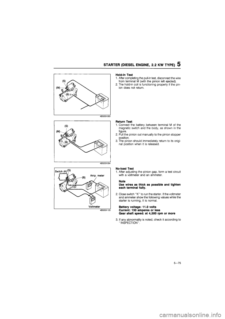
Hold-in Test
1. After completing the pull-in test, disconnect the wire
from terminal M (with the pinion left ejected).
2. The hold-in coil is functioning properly if the pin-
ion does not return.
4BG05X-093
Return Test
1. Connect the battery between terminal M of the
magnetic switch and the body, as shown in the
figure.
2. Pull the pinion out manually to the pinion stopper
position.
3. The pinion should immediately return to its origi-
nal position when it is released.
4BG05X-094
No-load Test
1. After adjusting the pinion gap, form a test circuit
with a voltmeter and an ammeter.
Note
Use wires as thick as possible and tighten
each terminal fully.
2. Close switch "K" to run the starter.
If
the voltmeter
and ammeter show the following values while the
starter is running, it is normal.
Battery voltage: 11.0 volts
Current: 130 amperes or less
Gear shaft speed: at 4,500 rpm or more
3. If any abnormality is noted, check it according to
"INSPECTION".
5—75
Page 784 of 1865
QUICK START SYSTEM (QSS) 5
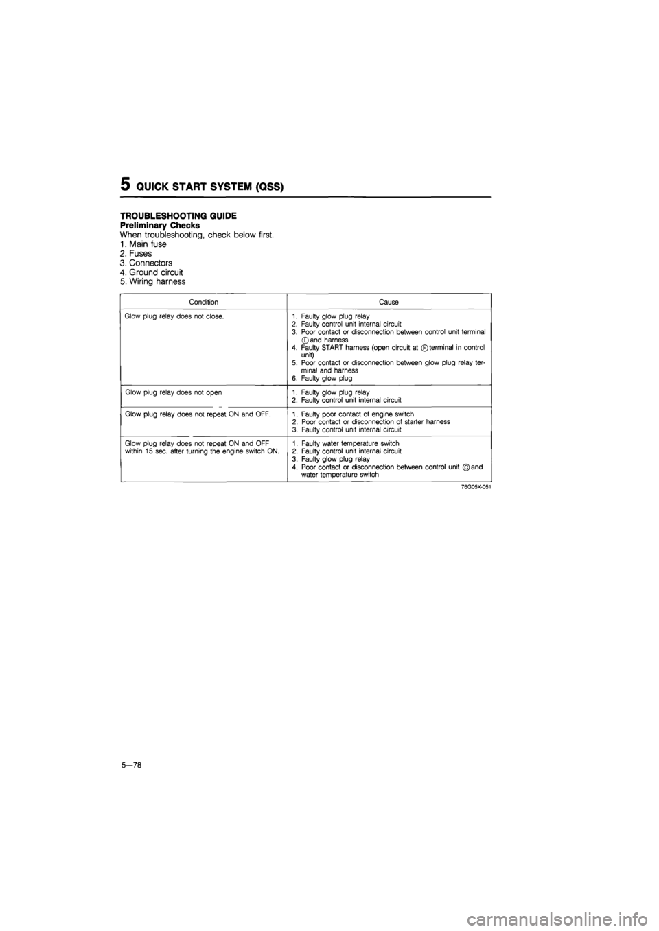
TROUBLESHOOTING GUIDE
Preliminary Checks
When troubleshooting, check below first.
1. Main fuse
2. Fuses
3. Connectors
4. Ground circuit
5. Wiring harness
Condition Cause
Glow plug relay does not close. 1. Faulty glow plug relay 2. Faulty control unit internal circuit
3. Poor contact or disconnection between control unit terminal ©and harness
4. Faulty START harness (open circuit at ©terminal in control unit) 5. Poor contact or disconnection between glow plug relay ter-minal and harness 6. Faulty glow plug
Glow plug relay does not open 1. Faulty glow plug relay 2. Faulty control unit internal circuit
Glow plug relay does not repeat ON and OFF. 1. Faulty poor contact of engine switch 2. Poor contact or disconnection of starter harness 3. Faulty control unit internal circuit
Glow plug relay does not repeat ON and OFF within 15 sec. after turning the engine switch ON. 1. Faulty water temperature switch 2. Faulty control unit internal circuit
3. Faulty glow plug relay
4. Poor contact or disconnection between control unit © and water temperature switch
76G05X-051
5-78
Page 785 of 1865
QUICK START SYSTEM (QSS) 5
CONTROL UNIT
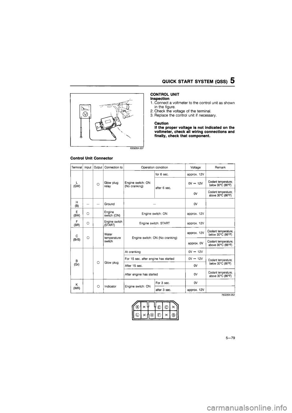
Inspection
1. Connect a voltmeter to the control unit as shown
in the figure.
2. Check the voltage of the terminal.
3. Replace the control unit if necessary.
Caution
If the proper voltage is not indicated on the
voltmeter, check all wiring connections and
finally, check that component.
63G05X-337
Control Unit Connector
Terminal Input Output Connection to Operation condition Voltage Remark
for 6 sec. approx. 12V
L (GW) O Glow plug relay Engine switch: ON (No cranking) after 6 sec.
OV 12V Coolant temperature; below 30°C (86°F) after 6 sec.
OV Coolant temperature; above 30°C (86°F)
H
(B) — — Ground OV
E (BW) 0 Engine switch (ON) Engine switch: ON approx. 12V
F
(BR) O Engine switch (START) Engine switch: START approx. 12V
C o
Water
temperature switch
Engine switch: ON (No cranking)
approx. 12V Coolant temperature; below 30°C (86°F)
(BrB) o
Water
temperature switch
Engine switch: ON (No cranking)
approx. OV Coolant temperature;
above 30°C (86°F)
At cranking OV <- 12V
B 0 Glow plug
For 15 sec. after engine has started OV <-> 12V Coolant temperature;
(Gr) 0 Glow plug After 15 sec. OV below 30°C (86 °F)
After engine has started OV Coolant temperature; above 30°C (86°F)
K o Indicator Engine switch: ON
For 3 sec. OV
(WR) o Indicator Engine switch: ON after 3 sec. approx. 12V
76G05X-052
u® x y i © © X 1
© © X ®
5-79
Page 892 of 1865
7B TROUBLESHOOTING (G4A-EL)
Item Indication Condition
OUTPUT (Digital display)
1
1
st gear position
GEAR* 2 2nd gear position GEAR*
3 3rd gear position
4 Overdrive (OD) gear position
86U07B-033
Note
a) The back-up condition is as following condition
S range, hold mode, and the accelerator pedal depressed fully.
b)The * marked items should be checked during the engine running or driving.
Comprehensive Usage
The EC-AT Tester can be used to inspect slippage of friction elements, shift points, and shift sequence
during the road test.
The inspection procedure is shown in STEP 7 (ROAD TEST).
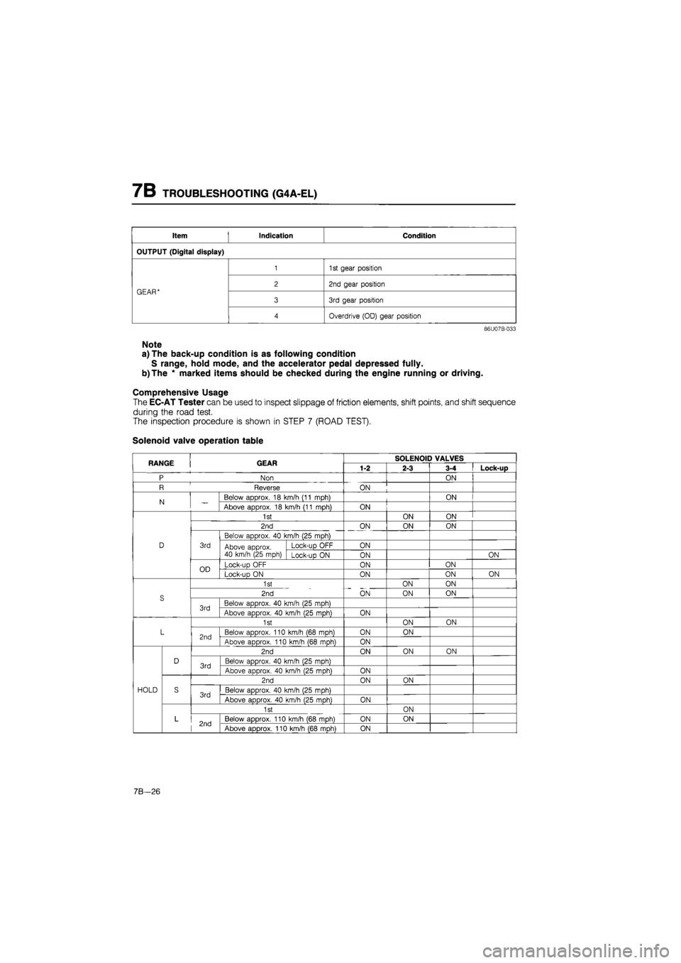
Solenoid valve operation table
RANGE GEAR SOLENOID VALVES RANGE GEAR 1-2 2-3 3-4 Lock-up
P Non ON
R Reverse ON
N Below aDDrox. 18 km/h (11 mDh) ON N Above approx. 18 km/h (11 mph) ON
1st ON ON
2nd ON ON ON
Below approx. 40 km/h (25 mph)
D 3rd Above approx. 40 km/h (25 mph)
Lock-uo OFF ON Above approx. 40 km/h (25 mph) Lock-up ON ON ON
OD Lock-up OFF ON ON OD Lock-uo ON ON ON ON
1st ON ON
S 2nd ON ON ON S
3rd Below approx. 40 km/h (25 mph) 3rd Above approx. 40 km/h (25 mph) ON
1st ON ON
L 2nd Below approx. 110 km/h (68 mph) ON ON 2nd Above approx. 110 km/h (68 moh) ON
2nd ON ON ON
D 3rd Below approx. 40 km/h (25 moh) 3rd Above approx. 40 km/h (25 moh) ON
2nd ON ON
HOLD S 3rd Below approx. 40 km/h (25 mph) 3rd Above approx. 40 km/h (25 mph) ON
1st ON
L 2nd Below approx. 110 km/h (68 mph) ON ON 2nd Above approx. 110 km/h (68 mph) ON
7B—26
Page 893 of 1865
TROUBLESHOOTING (G4A-EL) 7B
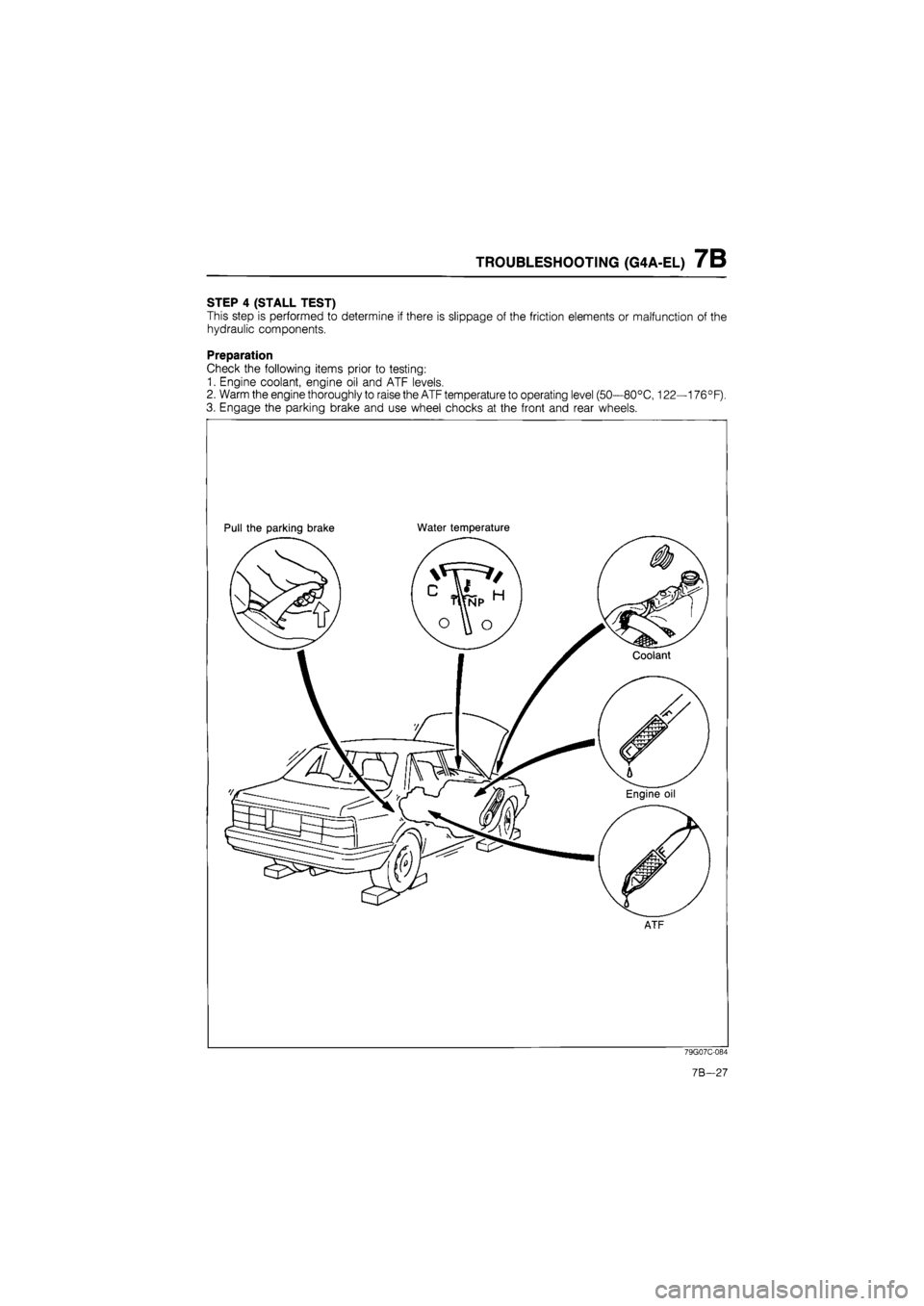
STEP 4 (STALL TEST)
This step is performed to determine if there is slippage of the friction elements or malfunction of the
hydraulic components.
Preparation
Check the following items prior to testing:
1. Engine coolant, engine oil and ATF levels.
2. Warm the engine thoroughly to raise the ATF temperature to operating level (50—80°C, 122—176°F).
3. Engage the parking brake and use wheel chocks at the front and rear wheels.
Pull the parking brake Water temperature
ATF
79G07C-084
7B-27
Page 896 of 1865
7B TROUBLESHOOTING (G4A-EL)
STEP 5 (TIME LAG TEST)
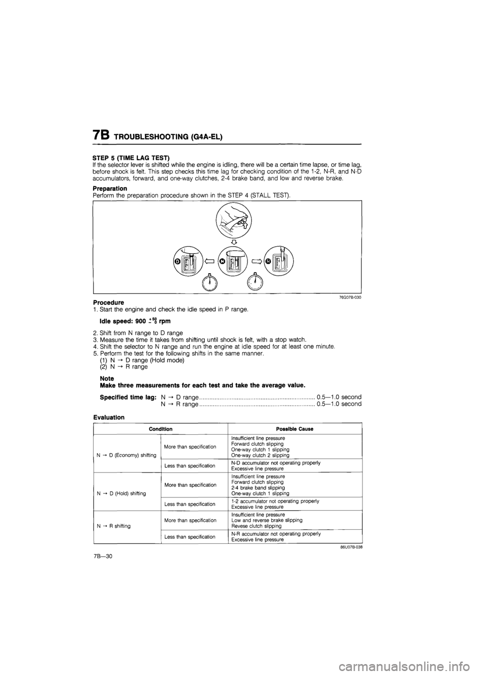
If the selector lever is shifted while the engine is idling, there will be a certain time lapse, or time lag,
before shock is felt. This step checks this time lag for checking condition of the 1-2, N-R, and N-D
accumulators, forward, and one-way clutches, 2-4 brake band, and low and reverse brake.
Preparation
76G07B-030
Procedure
1. Start the engine and check the idle speed in P range.
Idle speed: 900 ±58 rpm
2. Shift from N range to D range
3. Measure the time it takes from shifting until shock is felt, with a stop watch.
4. Shift the selector to N range and run the engine at idle speed for at least one minute.
5. Perform the test for the following shifts in the same manner.
(1) N D range (Hold mode)
(2) N -» R range
Note
Make three measurements for each test and take the average value.
Specified time lag: N -> D range
N -»• R range
Evaluation
Condition Possible Cause
N D (Economy) shifting
More than specification
Insufficient line pressure Forward clutch slipping One-way clutch 1 slipping One-way clutch 2 slipping N D (Economy) shifting
Less than specification N-D accumulator not operating properly
Excessive line pressure
N-D (Hold) shifting
More than specification
Insufficient line pressure Forward clutch slipping 2-4 brake band slipping One-way clutch 1 slipping N-D (Hold) shifting
Less than specification 1-2 accumulator not operating properly
Excessive line pressure
N R shifting
More than specification
Insufficient line pressure Low and reverse brake slipping Revese clutch slipping N R shifting
Less than specification N-R accumulator not operating properly
Excessive line pressure
86U07B-038
0.5—1.0 second
0.5—1.0 second
7B-30
Page 897 of 1865
TROUBLESHOOTING (G4A-EL) 7B
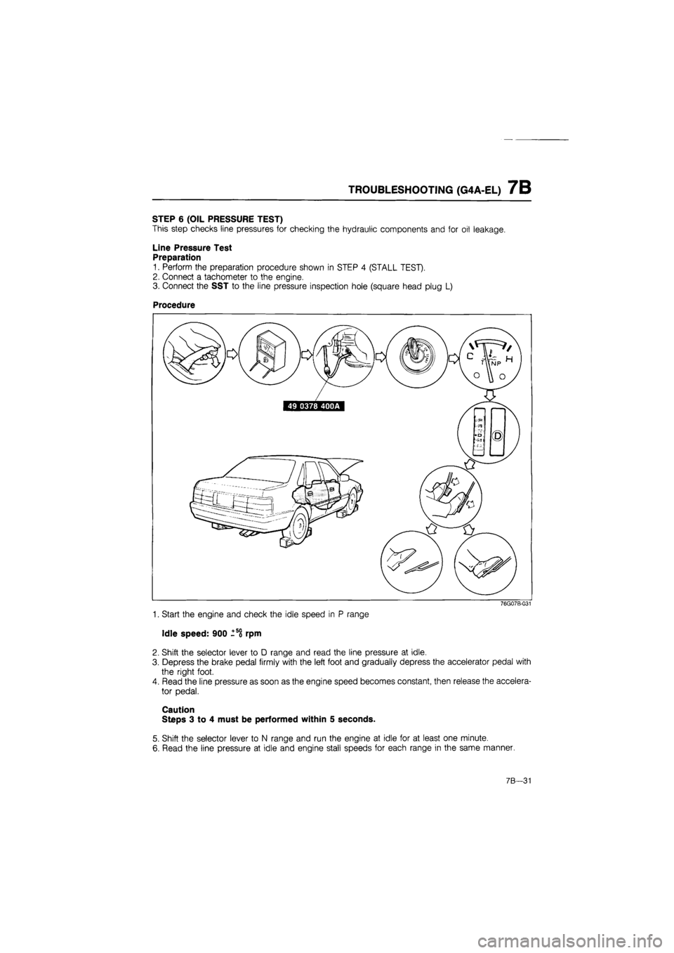
STEP 6 (OIL PRESSURE TEST)
This step checks line pressures for checking the hydraulic components and for oil leakage.
Line Pressure Test
Preparation
1. Perform the preparation procedure shown in STEP 4 (STALL TEST).
2. Connect a tachometer to the engine.
3. Connect the SST to the line pressure inspection hole (square head plug L)
Procedure
76G07B-031
1. Start the engine and check the idle speed in P range
Idle speed: 900 -so rpm
2. Shift the selector lever to D range and read the line pressure at idle.
3. Depress the brake pedal firmly with the left foot and gradually depress the accelerator pedal with
the right foot.
4. Read the line pressure as soon as the engine speed becomes constant, then release the accelera-
tor pedal.
Caution
Steps 3 to 4 must be performed within 5 seconds.
5. Shift the selector lever to N range and run the engine at idle for at least one minute.
6. Read the line pressure at idle and engine stall speeds for each range in the same manner.
7B—31
Page 899 of 1865
TROUBLESHOOTING (G4A-EL) 7B
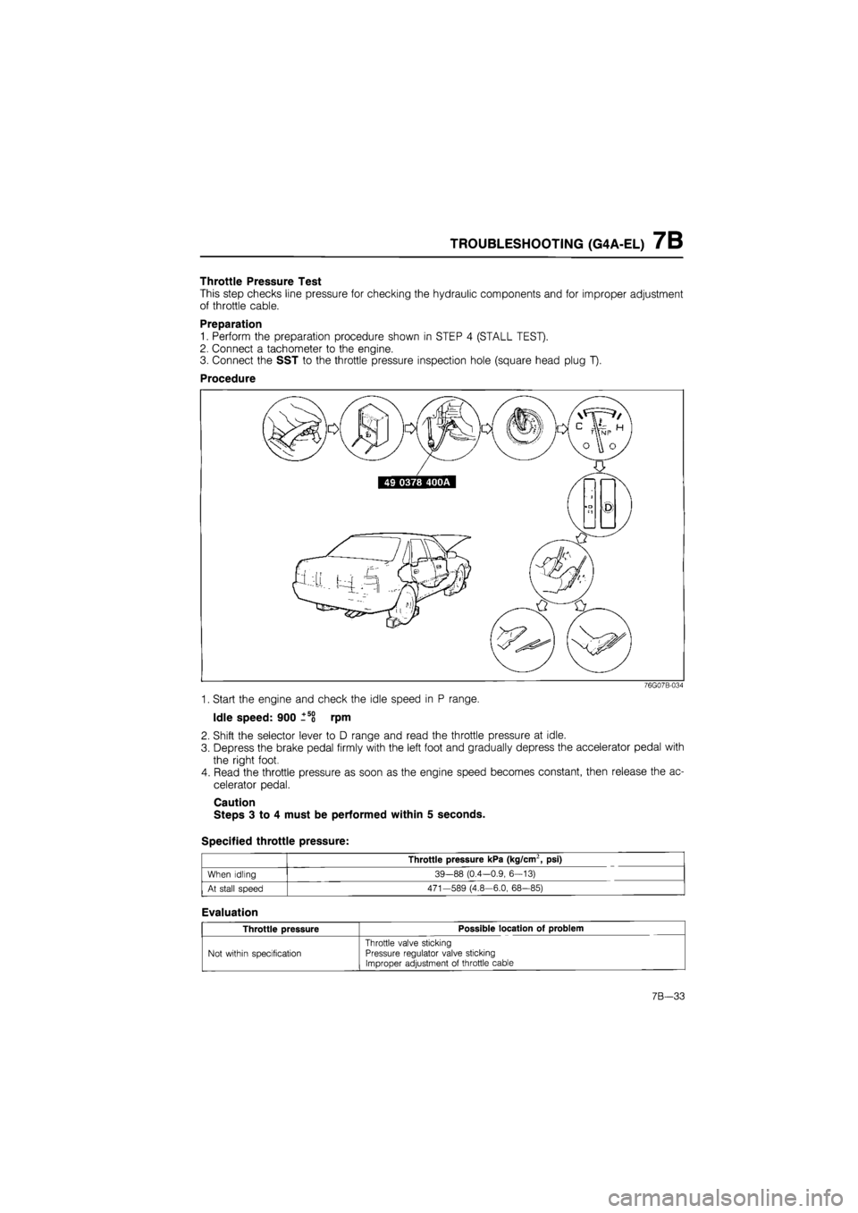
Throttle Pressure Test
This step checks line pressure for checking the hydraulic components and for improper adjustment
of throttle cable.
Preparation
1. Perform the preparation procedure shown in STEP 4 (STALL TEST).
2. Connect a tachometer to the engine.
3. Connect the SST to the throttle pressure inspection hole (square head plug T).
Procedure
76G07B-034
1. Start the engine and check the idle speed in P range.
Idle speed: 900 _5o rpm
2. Shift the selector lever to D range and read the throttle pressure at idle.
3. Depress the brake pedal firmly with the left foot and gradually depress the accelerator pedal with
the right foot.
4. Read the throttle pressure as soon as the engine speed becomes constant, then release the ac-
celerator pedal.
Caution
Steps 3 to 4 must be performed within 5 seconds.
Specified throttle pressure:
Throttle pressure kPa (kg/cm2, psi)
When idling 39-88 (0.4—0.9, 6—13)
At stall speed 471—589 (4.8—6.0, 68—85)
Evaluation
Throttle pressure Possible location of problem
Not within specification
Throttle valve sticking Pressure regulator valve sticking Improper adjustment of throttle cable
7B—33