check engine MAZDA 626 1987 Workshop Manual
[x] Cancel search | Manufacturer: MAZDA, Model Year: 1987, Model line: 626, Model: MAZDA 626 1987Pages: 1865, PDF Size: 94.35 MB
Page 922 of 1865

7B TROUBLESHOOTING (G4A-HL)
F8 engine
8/8-1
7/8-
6/8-
O) I
i ! O) Q.
o 3/8- [ ^ I o
jE 2/8-1 I
1/8- |
0/8 ' 1 ' 1 ' 1 1 1 1 1 1— ' l 0 20 40 60 80 100 120 140 (12) (25) (37) (50) (63) (74) (87)
Vehicle speed km/h (mph)
76G07B-060
Noise and vibration
Drive the vehicle in 1st gear and check for abnormal noise or vibration.
Note
Abnormal noise and vibration can also be caused by the torque converter, drive shaft or
differential. Therefore, checking of cause must be made with extreme care.
P Range Test
1. Shift into P range on a gentle slope, release the brake and check that the vehicle does not roll.
2. Shift into P range while driving the vehicle at maximum of 4 km/h (2.5 mph) on a level surface,
and check that the vehicle stops.
Vehicle Speed at Gearshift Table
Range Throttle condition Shifting Vehicle speed km/h (mph) Range Throttle condition Shifting FE engine F8 engine
D
Fully opened 1st ->• 2nd 50-65 (31-40) 47-62 (29-38)
D
Fully opened 2nd - 3rd 100-115 (62-71) 94-109 (58—68)
D
Half throttle (1/2)
1st - 2nd 17-32 (11-20) 16—31 (10—19)
D
Half throttle (1/2) 2nd -> 3rd 42-57 (26-35)
D
Half throttle (1/2) 3rd -> OD 79-94 (49-58) 74-89 (46-55)
D
Half throttle (1/2)
Lock-up 74-89 (46-55) D
Kick-down
OD - 3rd More than 88 (55) More than 82 (51) D
Kick-down
OD -> 2nd 34-103 (21-64) 33-97 (20-60)
D
Kick-down OD - 1st 27-49 (17-30) 26-48 (16-30)
D
Kick-down 3rd - 2nd 34—103 (21-64) 33-97 (20-60)
D
Kick-down
3rd - 1st
11
-49 (7—30) 10-48 (6-30)
D
Kick-down
2nd - 1st
1st - 2nd
4-49 (2-30) 3-48 (2-30)
1
Fully opened
2nd - 1st
1st - 2nd 56-71 (35-44) 52—67 (32—42)
1 Half throttle (1/2) 1st - 2nd 56-71 (35-44) 52-67 (32—42) 1
Kick-down 2nd -> 1st 46-61 (29-38) 43-58 (27-36)
D Fully opened 3rd lock-up 106-121 (66—75) 100-115 (62-71)
7B-56
Page 923 of 1865

TROUBLESHOOTING (G4A-HL) 7B
Evaluation
Condition Possible Cause
No 1-2 shift
Insufficient governor pressure
No 1-2 shift
Stuck 1 range control valve
No 1-2 shift Stuck 1-2 shift control valve No 1-2 shift
Stuck 1-2 shift valve
No 1-2 shift
No check ball (rubber ball)
No 2-3 shift
Insufficient governor pressure
No 2-3 shift
Stuck 2 range control valve
No 2-3 shift Stuck servo control valve No 2-3 shift
Stuck 2-3 shift valve
No 2-3 shift
No check ball (rubber ball)
No 3-OD shift
Insufficient governor pressure
No 3-OD shift
Excessive throttle pressure
No 3-OD shift Stuck OD release valve No 3-OD shift Stuck needle valve of the OD release solenoid valve No 3-OD shift
Stuck 3-4 shift valve
No 3-OD shift
No check ball (rubber ball)
No. Lock-up (Electric circuit is OK)
Insufficient governor pressure
No. Lock-up (Electric circuit is OK)
Stuck OD release valve
Stuck needle valve of the OD release solenoid valve No. Lock-up (Electric circuit is OK)
Stuck OD lock-up valve
No. Lock-up (Electric circuit is OK)
Stuck lock-up control valve
Shift occurred in 2 range Stuck 1-2 control valve Shift occurred in 2 range Stuck 2 range control valve
No kick-down Stuck throttle valve No kick-down Stuck kick-down valve
Incorrect shift point In D and 1 range
Excessive or insufficient governor pressure
Incorrect shift point In D and 1 range Excessive or insufficient throttle pressure Incorrect shift point In D and 1 range
Excessive or insufficient line pressure Incorrect shift point
In 1 range Stuck 1 range control valve
No engine braking effect
Stuck coasting bypass valve
No engine braking effect Fluid leakage from 2-3 accumulator seal rings No engine braking effect
No check ball (rubber ball)
Shift shock or slippage
In 1-2 and/or 3-OD shift
Fluid leakage from 1-2 accumulator seal rings
Shift shock or slippage
In 1-2 and/or 3-OD shift No check ball (rubber ball) or leakage
Shift shock or slippage
In 1-2 and/or 3-OD shift
No one-way check orifice or leakage
Shift shock or slippage In 2-3 shift
Fluid leakage from 2-3 accumulator seal ring
Shift shock or slippage In 2-3 shift
Stuck bypass valve
Shift shock or slippage In 2-3 shift
Stuck 2-3 timing valve
Shift shock or slippage In 2-3 shift Stuck coast bypass valve Shift shock or slippage In 2-3 shift
Stuck servo control valve Shift shock or slippage In 2-3 shift
No one-way check orifice or leakage
Shift shock or slippage In 2-3 shift
No check ball (rubber ball) or leakage
Shift shock or slippage
In 3-2 shift
Fluid leakage from 1-2 accumulator seal ring
Shift shock or slippage
In 3-2 shift No check ball (rubber ball) or leakage
Shift shock or slippage
In 3-2 shift Stuck 3-2 timing valve
Shift shock or slippage
In 3-2 shift
Stuck 3-2 capacity valve
83U07B-046
7B—57
Page 924 of 1865

7B TROUBLESHOOTING (G4A-HL)
Line Pressure Test
Preparation
1. Connect the SST to the line pressure output point
(square head plug L).
2. Connect a tachometer to the engine.
3. Perform the preparation procedure shown in STEP
3 (STALL TEST).
STEP 6 (OIL PRESSURE TEST)
This step checks line, throttle, and governor pressures to check the operation of hydraulic compo-
nents and for oil leakage.
83U07B-047
Procedure
76G07B-062
1. Start the engine and check that the idle speed is 900 rpm.
2. Shift the selector lever to D range.
3. Read the line pressure at idle.
4. Depress the brake pedal firmly with the left foot and gradually depress the accelerator pedal with
the right foot.
5. Read the line pressure as soon as the engine speed becomes constant, then release the accelera-
tor pedal.
Caution
Steps 4 to 5 must be performed within 5 seconds.
5. Shift the selector lever to N range and run the engine at idle for at least one minute.
6. Read the line pressure at idle and engine stall speeds for each range in the same manner.
7B—58
Page 926 of 1865

7B TROUBLESHOOTING (G4A-HL)
Throttle Pressure Test
Preparation
1. Connect the SST to the throttle pressure output
point (Square head plug T).
2. Connect a tachometer to the engine.
3. Perform the preparation procedure shown in STEP
3 (STALL TEST).
83U07B-052
Procedure
76G07B-064
1. Start the engine and check that the idle speed is 900 _5o rpm.
2. Shift the selector to D range.
3. Read the throttle pressure at idle.
4. Depress the brake pedal firmly with the left foot and gradually depress the accelerator pedal with
the right foot.
5. Read the throttle pressure as soon as the engine speed becomes constant, then release the ac-
celerator pedal.
Caution
Steps 4 to 5 must be performed within 5 seconds.
7B-60
Page 928 of 1865

7B TROUBLESHOOTING (G4A-HL)
Governor Pressure Test
Preparation
1. Connect the SST to the governor pressure output
point.
2. Place the pressure gauge inside the vehicle.
3. Warm up ATF and check ATF level.
83U07B-054
Procedure
76G07B-065
1. Drive the vehicle in D range.
2. Read the governor pressure at the speeds listed in the table below.
Specified governor pressure:
Vehicle Speed km/h (mph) Governor Pressure kPa (kg/cm2, psi) Vehicle Speed km/h (mph) FE engine F8 engine
30 (19) 79-114 (0.81-1.16, 12-16) 82-117 (0.84-1.19, 12-17)
55 (34) 146-190 (1.49-1.94, 21-28) 157-201 (1.60-2.05, 23-29)
85 (53) 276-339 (2.81-3.46, 40-49) 302-366 (3.08-3.73, 44-53)
Evaluation
Condition Possible Cause
Not within specification
Fluid leakage from the line pressure hydraulic circuit
Not within specification Fluid leakage from the governor pressure hydraulic circuit Not within specification
Defective or stuck governor valve
7B-62
Page 936 of 1865

7B ELECTRICAL SYSTEM COMPONENTS
Terminal Connected to Voltage Condition
1J — — —
1K — — —
1L (Input) Idle switch Below 1.5V At idle 1L (Input) Idle switch Approx. 12V Other speeds
1M — — —
1N (Input) Brake light switch Approx. 12V Brake pedal depressed 1N (Input) Brake light switch Below 1.5V Brake pedal released
10 (Input) Throttle sensor
Approx. 5V Ignition switch ON 10 (Input) Throttle sensor Below 1,5V Ignition switch OFF
1P (Input)
Throttle sensor
Approx. 0.5—4.3V Throttle valve fully closed to fully open
1Q (Input) Vehicle speed sensor
Approx. 4.5V During driving
1Q (Input) Vehicle speed sensor Approx. 4.5V or below 1.5V Vehicle stopped
1R (Ground) Throttle sensor Below 1,5V —
1S (Input) Pulse generator Approx. 12V Engine running 1S (Input) Pulse generator Below 1,5V Engine stopped
1S (Ground) Pluse generator Below 1.5V —
2A (Battery power) Battery Approx. 12V Ignition switch ON 2A (Battery power) Battery Below 1,5V Ignition switch OFF
2B (Ground) Body ground Below 1,5V —
2C (Memory power) Battery Approx. 12V —
2D (Ground) Body ground Below 1,5V —
2E (Output) 1-2 shift solenoid valve Approx. 12V
Refer to page 7B—26 of solenoid valve
operation table
2E (Output) 1-2 shift solenoid valve Below 1.5V Refer to page 7B—26 of solenoid valve
operation table
2F (Output) 2-3 shift solenoid valve Approx. 12V
Refer to page 7B—26 of solenoid valve
operation table
2F (Output) 2-3 shift solenoid valve Below 1,5V
Refer to page 7B—26 of solenoid valve
operation table
2G — — —
2H (Output) 3-4 shift solenoid valve Approx. 12V Refer to page 7B—26 of solenoid valve operation table 2H (Output) 3-4 shift solenoid valve Below 1.5V
Refer to page 7B—26 of solenoid valve operation table
21 — — —
2J (Output) Lock-up solenoid valve Approx. 12V Lock-up 2J (Output) Lock-up solenoid valve Below 1,5V Other
2K (Output) Hold indicator Below 1,5V Hold mode 2K (Output) Hold indicator Approx. 12V Other modes
2L (Output) Mode indicator Approx. 12V Hold mode 2L (Output) Mode indicator Below 1,5V Power or economy mode
2M (Output) EC-AT Tester
(malfunction code)
Approx. 12V Normal
2M (Output) EC-AT Tester
(malfunction code) Below 1,5V If malfunction present 2M (Output) EC-AT Tester
(malfunction code) Code signal Self-diagnosis check connector grounded
2N — — —
20 (Input) Fluid temperature switch Below 1,5V Above 150°C (302°F) 20 (Input) Fluid temperature switch Approx. 10—12V Below 143°C (289°F)
2P (Input) EC-AT check connect Approx. 12V —
76G07B-084
7B-70
Page 937 of 1865

ON-VEHICLE MAINTENANCE 7B
ON-VEHICLE MAINTENANCE
AUTOMATIC TRANSAXLE FLUID (ATF)
Inspection for Fluid Leaks
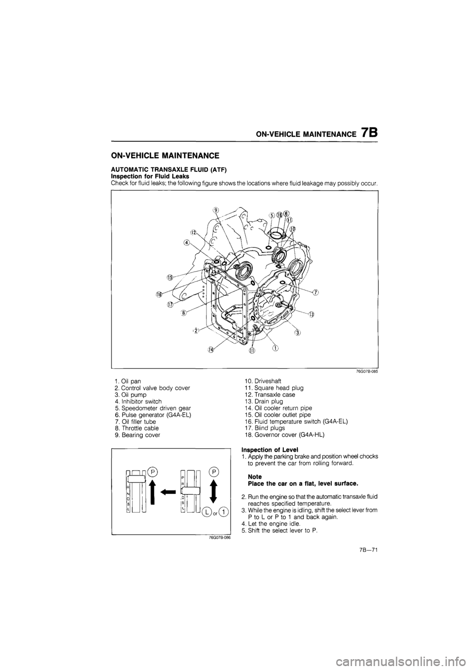
Check for fluid leaks; the following figure shows the locations where fluid leakage may possibly occur.
1. Oil pan
2. Control valve body cover
3. Oil pump
4. Inhibitor switch
5. Speedometer driven gear
6. Pulse generator (G4A-EL)
7. Oil filler tube
8. Throttle cable
9. Bearing cover
76G07B-085
10. Driveshaft
11. Square head plug
12. Transaxle case
13. Drain plug
14. Oil cooler return pipe
15. Oil cooler outlet pipe
16. Fluid temperature switch (G4A-EL)
17. Blind plugs
18. Governor cover (G4A-HL)
Inspection of Level
1. Apply the parking brake and position wheel chocks
to prevent the car from rolling forward.
Note
Place the car on a flat, level surface.
2. Run the engine so that the automatic transaxle fluid
reaches specified temperature.
3. While the engine is idling, shift the select lever from
P to L or P to 1 and back again.
4. Let the engine idle.
5. Shift the select lever to P.
76G07B-086
7B—71
Page 941 of 1865

ON-VEHICLE MAINTENANCE 7B
'mfm^i! kfOl iff t—
76G07B-093
76G07B-094
Main fuse block (G4A-EL)
Install the main fuse block.
Tightening torque:
8—11 Nm (80—110 cm-kg, 69—95 in-lb)
Battery carrier
Install the battery carrier.
Tightening torque:
31—40 Nm (3.2—4.1 m-kg, 23—30 ft-lb)
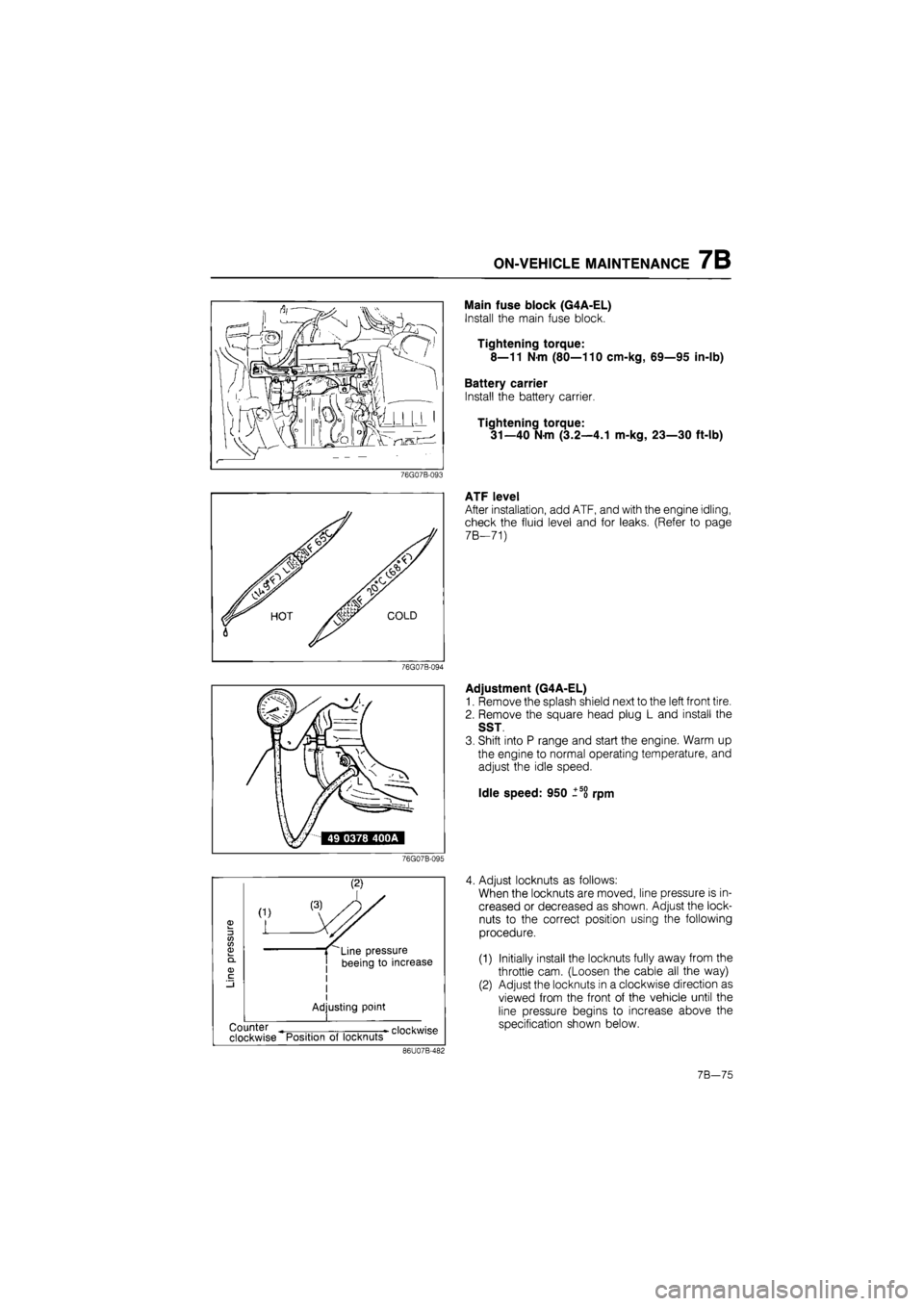
ATF level
After installation, add ATF, and with the engine idling,
check the fluid level and for leaks. (Refer to page
7 B—71)
Adjustment (G4A-EL)
1. Remove the splash shield next to the left front tire.
2. Remove the square head plug L and install the
SST
3. Shift into P range and start the engine. Warm up
the engine to normal operating temperature, and
adjust the idle speed.
Idle speed: 950 ±5o rpm
76G07B-095
3 CO CO 03
(1)
L
Line pressure
beeing to increase
I
Adjusting point
•
clockwise Counter
clockwise Position of locknuts
86U07B-482
4. Adjust locknuts as follows:
When the locknuts are moved, line pressure is in-
creased or decreased as shown. Adjust the lock-
nuts to the correct position using the following
procedure.
(1) Initially install the locknuts fully away from the
throttle cam. (Loosen the cable all the way)
(2) Adjust the locknuts in a clockwise direction as
viewed from the front of the vehicle until the
line pressure begins to increase above the
specification shown below.
7B—75
Page 944 of 1865

7B ON-VEHICLE MAINTENANCE
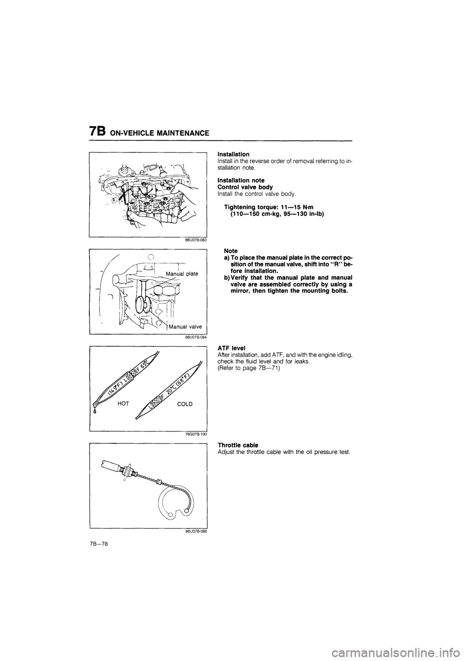
Installation
Install in the reverse order of removal referring to in-
stallation note.
Installation note
Control valve body
Install the control valve body.
Tightening torque: 11—15 N-m
(110—150 cm-kg, 95—130 in-lb)
86U07B-083
Note
a) To place the manual plate in the correct po-
sition of the manual valve, shift into "R" be-
fore installation.
b) Verify that the manual plate and manual
valve are assembled correctly by using a
mirror, then tighten the mounting bolts.
86U07B-084
w v
ATF level
After installation, add ATF, and with the engine idling,
check the fluid level and for leaks.
(Refer to page 7B—71)
76G07B-100
Throttle cable
Adjust the throttle cable with the oil pressure test.
86U07B-086
7B-78
Page 946 of 1865

7B ON-VEHICLE MAINTENANCE
86U07B-091
76G07B-101
76G07B-102
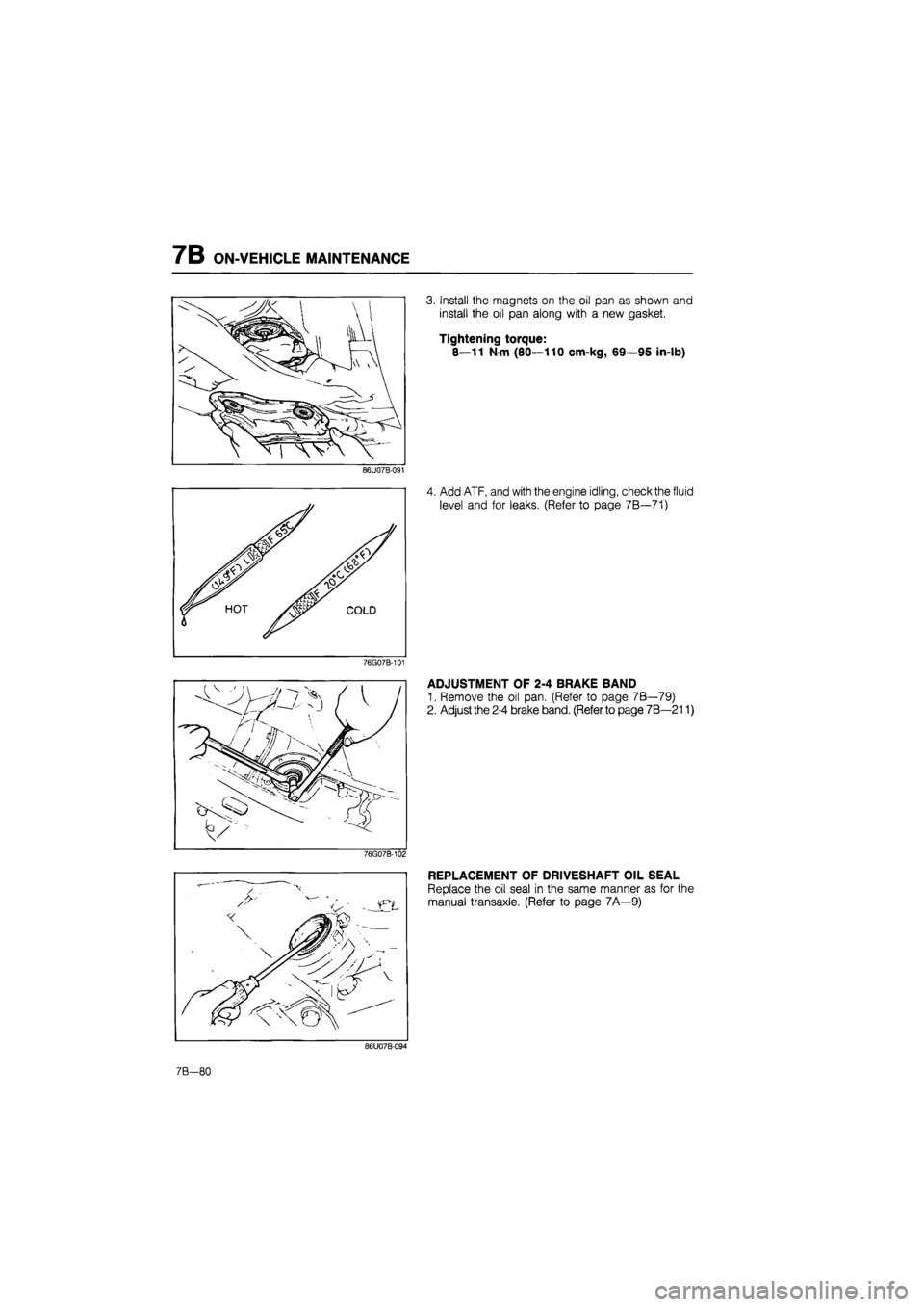
3. Install the magnets on the oil pan as shown and
install the oil pan along with a new gasket.
Tightening torque:
8—11 Nm (80—110 cm-kg, 69—95 in-lb)
4. Add ATF, and with the engine idling, check the fluid
level and for leaks. (Refer to page 7B—71)
ADJUSTMENT OF 2-4 BRAKE BAND
1. Remove the oil pan. (Refer to page 7B—79)
2. Adjust the 2-4 brake band. (Refer to page 7B—211)
REPLACEMENT OF DRIVESHAFT OIL SEAL
Replace the oil seal in the same manner as for the
manual transaxle. (Refer to page 7A—9)
86U07B-094
7B-80