engine MAZDA 626 1987 Owner's Manual
[x] Cancel search | Manufacturer: MAZDA, Model Year: 1987, Model line: 626, Model: MAZDA 626 1987Pages: 1865, PDF Size: 94.35 MB
Page 39 of 1865

1A TUNE-UP PROCEDURE
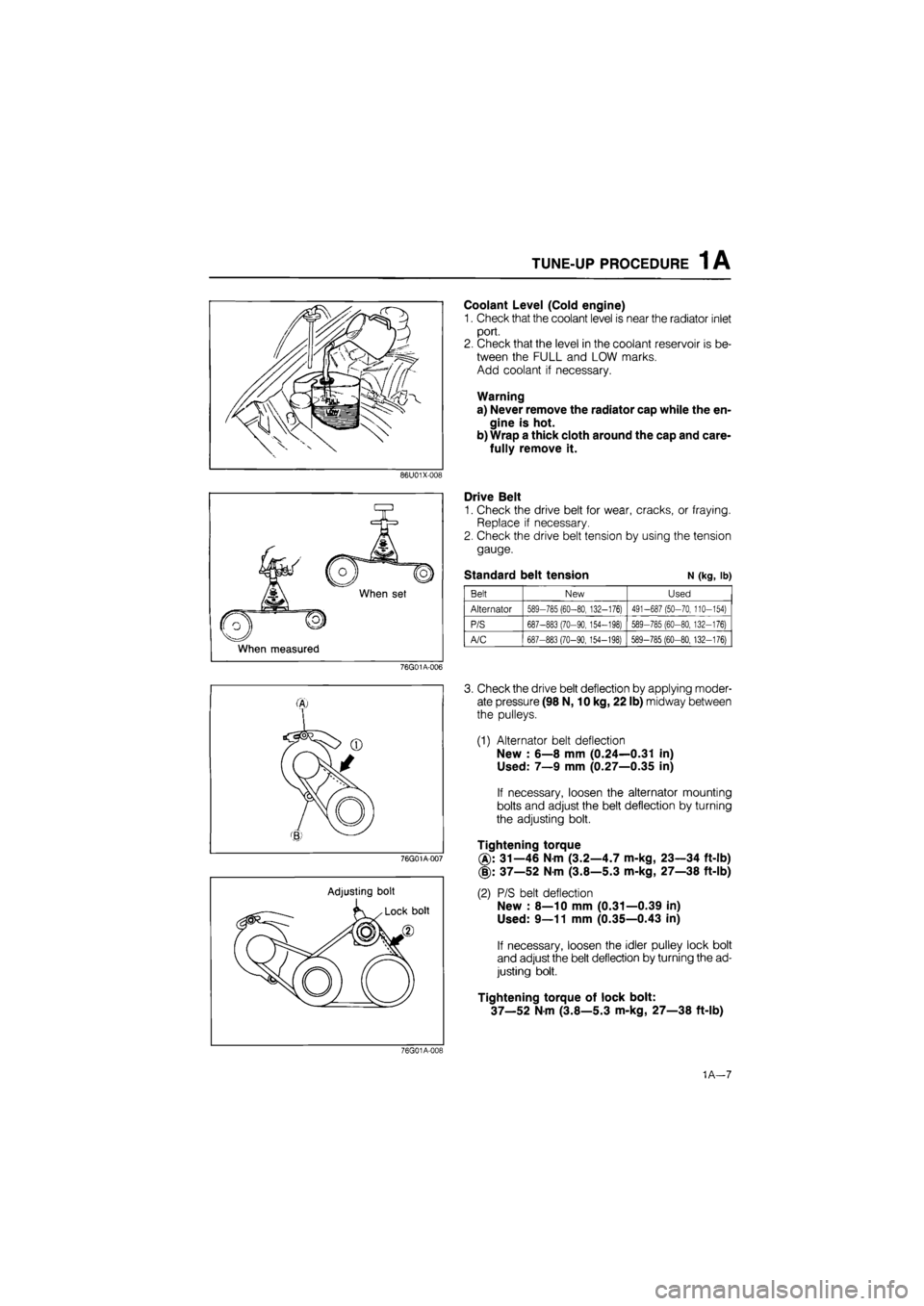
Coolant Level (Cold engine)
1. Check that the coolant level is near the radiator inlet
port.
2. Check that the level in the coolant reservoir is be-
tween the FULL and LOW marks.
Add coolant if necessary.
Warning
a) Never remove the radiator cap while the en-
gine is hot.
b) Wrap a thick cloth around the cap and care-
fully remove it.
86U01X-008
When set
When measured
Drive Belt
1. Check the drive belt for wear, cracks, or fraying.
Replace if necessary.
2. Check the drive belt tension by using the tension
gauge.
Standard belt tension N (kg, lb)
Belt New Used
Alternator 589-785 (60-80, 132-176) 491-687 (50-70, 110-154)
P/S 687-883 (70-90, 154-198) 589-785 (60-80, 132-176)
A/C 687-883 (70-90,154-198) 589-785 (60-80, 132-176)
76G01A-006
76G01A-007
Adjusting bolt
3. Check the drive belt deflection by applying moder-
ate pressure (98 N, 10 kg, 22 lb) midway between
the pulleys.
(1) Alternator belt deflection
New : 6—8 mm (0.24—0.31 in)
Used: 7—9 mm (0.27—0.35 in)
If necessary, loosen the alternator mounting
bolts and adjust the belt deflection by turning
the adjusting bolt.
Tightening torque
31—46 Nm (3.2—4.7 m-kg, 23—34 ft-lb)
(§): 37—52 Nm (3.8—5.3 m-kg, 27—38 ft-lb)
(2) P/S belt deflection
New : 8—10 mm (0.31—0.39 in)
Used: 9—11 mm (0.35—0.43 in)
If necessary, loosen the idler pulley lock bolt
and adjust the belt deflection by turning the ad-
justing bolt.
Tightening torque of lock bolt:
37—52 Nm (3.8—5.3 m-kg, 27—38 ft-lb)
76G01A-019
1A—7
Page 41 of 1865

TUNE-UP PROCEDURE 1A
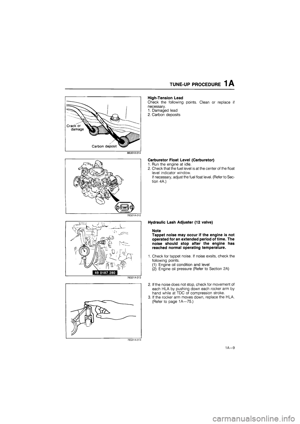
High-Tension Lead
Check the following points. Clean or replace if
necessary.
1. Damaged lead
2. Carbon deposits
86U01X-014
76G01A-012
49 0187 280
76G01A-013
Carburetor Float Level (Carburetor)
1. Run the engine at idle.
2. Check that the fuel level is at the center of the float
level indicator window.
If necessary, adjust the fuel float level. (Refer to Sec-
tion 4A.)
Hydraulic Lash Adjuster (12 valve)
Note
Tappet noise may occur if the engine is not
operated for an extended period of time. The
noise should stop after the engine has
reached normal operating temperature.
1. Check for tappet noise. If noise exsits, check the
following points.
(1) Engine oil condition and level
(2) Engine oil pressure (Refer to Section 2A)
2. If the noise does not stop, check for movement of
each HLA by pushing down each rocker arm by
hand while at TDC of compression stroke.
3. If the rocker arm moves down, replace the HLA.
(Refer to page 1A—75.)
76G01A-014
1
A—9
Page 42 of 1865

1A TUNE-UP PROCEDURE
No.1 IN No.2 IN
No.1 EX No.3 EX
76G01A-015
Adjust bolt
^N^^^^^Lock nut
SsKs&b ' Valve
Camshaft >Nw clearance
76G01A-016
76G01A-017
Valve Clearance (8-valve)
1. Warm up the engine to the normal operating tem-
perature.
2. With the piston of the No.1 cylinder at TDC of com-
pression stroke.
Adjust the valve clearance as shown in the figure.
Valve clearance (valve side)
IN : 0.30 mm (0.012 in)
EX: 0.30 mm (0.012 in)
3. Turn the crankshaft one full turn so that the piston
of the No.4 cylinder is at TDC of compression
stroke.
Adjust the clearances of the remaining valves.
Ignition Timing
1. Warm up the engine and run it at idle.
2. Turn all electric loads OFF.
3. Connect a timing light tester.
4. Disconnect the vacuum hose from the vacuum
control, and plug the hose.
5. Check that the ignition timing mark (yellow) on the
crankshaft pulley and the timing mark on the tim-
ing belt cover are aligned.
Ignition timing: 6° ±
1
° BTDC (at idle speed)
6. If necessary adjust the ignition timing by turning
the distributor.
69G01B-518
1A—10
Page 43 of 1865

1A TUNE-UP PROCEDURE
76G01A-105
Idle Speed (Carburetor)
1. Connect a tachometer to the engine.
2. Turn all electric loads OFF.
3. Confirm that the choke valve has fully returned at
idling speed.
4. Check the idle speed. If necessary, turn the throt-
tle adjust screw and adjust the idle speed.
Idle speed
MTX: 800 ±s8 rpm (in neutral)
ATX: 950
Is8
rpm (in "N" range) F6
900 I58 rpm (in "N" range).. FE, F8
Idle Speed (Fl)
1. Connect the tachometer to the engine.
2. Check the idle speed.
Idle speed
MTX: 850 i!°0 rpm (in neutral)
ATX: 850 t55°o rpm (in "N" range)
3. If necessary, remove the blind cap from the throt-
tle body and adjust by turning the air adjust screw.
4. Install the blind cap.
76G01A-018
Idle Mixture (Carburetor)
1. Disconnect the secondary air hoses from the reed
valves and then plug the hoses (if equipped).
2. Connect an exhaust gas analyzer to the vehicle as
shown in the figure and measure the CO concen-
tration.
76G01A-106
3. Remove the blind cap from the mixture adjust
screw.
Note
The blind cap will be broken when it is re-
moved, do not attempt to reinstall it.
76G01A-019
1A—11
Page 45 of 1865

ON-VEHICLE INSPECTION 1 A
ON-VEHICLE INSPECTION
If the engine exhibits low power, poor fuel economy,
or poor idle, check the following points.
1. Ignition system (Refer to Section 5)
2. Compression
3. Fuel system (Refer to Section 4)
COMPRESSION
1. Check that the battery is fully charged. Recharge
if necessary.
76G01A-107
2. Warm up the engine to the normal operating tem-
perature.
3. Turn it off for about 10 minutes to allow the exhaust
manifold to cool.
4. Remove all spark plugs.
5. Disconnect the primary wire connector from the
ignition coil.
86U01X-020
6. Connect a compression gauge to No.
1
spark plug
hole.
7. Fully depress the accelerator pedal and crank the
engine.
8. Note the maximum gauge reading.
9. Check each cylinder.
Compression pressure kPa (kg/cm2, psi)-rpm
Standard Minimum
F6 1,128 (11.5, 164)—270 790 (8.1, 114)—270
F8-FE 1,275 (13.0, 185)—270 893 (9.1, 129)—270
FE 12-valve 1,422 (14.5, 206)—280 996 (10.2, 144)—280
76G01A-023
Possible Cause
86U01X-022
1A—13
Page 46 of 1865

1 A ON-VEHICLE MAINTENANCE (TIMING BELT)
ON-VEHICLE MAINTENANCE
TIMING BELT
Removal
1. Disconnect the negative battery cable.
2. Remove in the sequence shown in the figure referring to the removal note for specially marked parts.
76G01A-108
76G01A-024
1. High-tension lead and spark plug
2. Engine side cover
3. Drive belt
4. Crankshaft pulley
5. Upper timing belt cover
6. Lower timing belt cover
7. Baffle plate
8. Timing belt tensioner
9. Timing belt tensioner spring
10. Timing belt
1A—14
Page 47 of 1865

1 A ON-VEHICLE MAINTENANCE (TIMING BELT)
Removal note
Timing belt tensioner
1. Turn the crankshaft to align the mating mark of the
camshaft pulley with the front housing timing mark.
Note
For FE engine, align "2" mark.
For F8, F6 engine, align "3" mark.
2. Remove the tensioner.
76G01A-025
Timing belt
Mark the timing belt rotation for proper reinstallation
if it is reused.
Caution
Be careful not to allow oil, grease, or water
on the belt.
86U01X-024
Inspection
Inspect the following parts.
(Refer to page 1A—60, 61.)
1. Timing belt
2. Timing belt tensioner and spring
3. Timing belt idler pulley
4. Timing belt pulley
5. Camshaft pulley
76G01A-026
1A—15
Page 49 of 1865

ON-VEHICLE MAINTENANCE (TIMING BELT) 1 A
76G01A-027
76G01B-024
76G01A-028
/Jf
ry.
2. Check that the mating mark of the camshaft pul-
ley is aligned with the timing mark. If it is not
aligned, turn the camshaft to align.
Note
For FE engine, align "2" mark.
For F8, F6 engine, align "3" mark.
3. Install the timing belt tensioner and spring. Tem-
porarily secure it with the spring fully extended.
Caution
Do not damage the pulleys when securing the
tensioner pulley.
4. Install the timing belt. (Keep the tension side of belt
as tight as possible).
Caution
a) If the timing belt is being reused, it must be
reinstalled to rotate in the original direction.
b) Check that there is no oil, grease, or dirt on
the timing belt.
5. Loosen the tensioner lock bolt.
6. Turn the crankshaft twice in the direction of rota-
tion, and align the mating marks.
7. Check that the timing marks are correctly aligned.
If not aligned, remove the timing belt tensioner and
timing belt, and repeat steps 1—6.
69G01B-027
1A-17
Page 51 of 1865

1 A ON-VEHICLE MAINTENANCE (TIMING BELT)
Spark plug
1. Apply anti-seize compound or molybdenum-based
lubricant to the spark plug threads.
2. Install the spark plugs.
Tightening torque:
15—23 N-m (1.5—2.3 m-kg, 11—17 ft-lb)
79G01C-021
Steps After Installation
Perform the necessary engine adjustment. (Refer to
TUNE-UP PROCEDURE.)
86U01X-029
1A—19
Page 52 of 1865

1 A ON-VEHICLE MAINTENANCE (CYLINDER HEAD)
CYLINDER HEAD
Removal
Warning: Release the fuel pressure. (Refer to Section 4.)
1. Disconnect the negative battery cable.
2. Drain the engine coolant.
3. Remove in the sequence shown in the figure referring to the removal note for specially marked parts.
76G01A-110
1A—20