engine MAZDA 626 1987 Repair Manual
[x] Cancel search | Manufacturer: MAZDA, Model Year: 1987, Model line: 626, Model: MAZDA 626 1987Pages: 1865, PDF Size: 94.35 MB
Page 119 of 1865

ASSEMBLY (AUXILIARY PARTS) 1 A
76G01A-087
76G01A-088
86U01X-167
Oil Pressure Switch
Install the oil pressure switch.
Tightening torque: 12—18 N-m
(1.2—1.8 m-kg, 104—156 in-lb)
Oil Cooler (8-valve...only ECE, 12-valve)
Install the oil cooler.
Tightening torque:
29—39 N-m (3.0—4.0 m-kg, 22—29 ft-lb)
Oil Filter
1. Apply engine oil to the rubber gasket of the new
filter.
2. Install the oil filter, and tighten it by hand only. Do
not use a wrench.
Intake Manifold Assembly
1. Place the new gasket in position.
2. Install the intake manifold assembly.
3. Tighten the nuts in two or three steps.
Tightening torque:
19—30 N-m (1.9—3.1 m-kg, 14—22 ft-lb)
Intake Manifold Bracket (Fl)
Install the intake manifold bracket.
Tightening torque:
19—30 N-m (1.9—3.1 m-kg, 14—22 ft-lb)
76G01A-092
1A—87
Page 120 of 1865

1 A ASSEMBLY (AUXILIARY PARTS)
86U01X-169
86U01X-219
76G01A-035
Thermostat and Thermostat Cover
1. Install the thermostat into the cylinder head with
the jiggle pin at the top.
2. Position a new gasket with the printed side facing
the cylinder head.
3. Install the thermostat cover.
Tightening torque:
19—30 Nm (1.9—3.1 m-kg, 14—22 ft-lb)
Spark Plug
1. Apply anti-seize compound or molybdenum-based
lubricant to the spark plug threads.
2. Install the spark plugs.
Tightening torque:
15—23 Nm (1.5—2.3 m-kg, 11—17 ft-lb)
Distributor
1. Apply engine oil to the O-ring, and position it on
the distributor.
2. Apply engine oil to the blade or gear.
3. Align the mating marks as shown in the figure
...8-valve.
4. Install the distributor with the marks facing straight
up.
5. Loosely tighten the distributor mounting bolt.
High-Tension Lead
Install the high-tension leads.
Engine Mount Bracket
Install the engine mount.
Tightening torque:
85—117 Nm (8.7—11.9 m-kg, 63—86 ft-lb)
86U01X-178
1A—88
Page 121 of 1865

ASSEMBLY (AUXILIARY PARTS) 1 A
86U01X-171
76G01A-090
76G01A-091
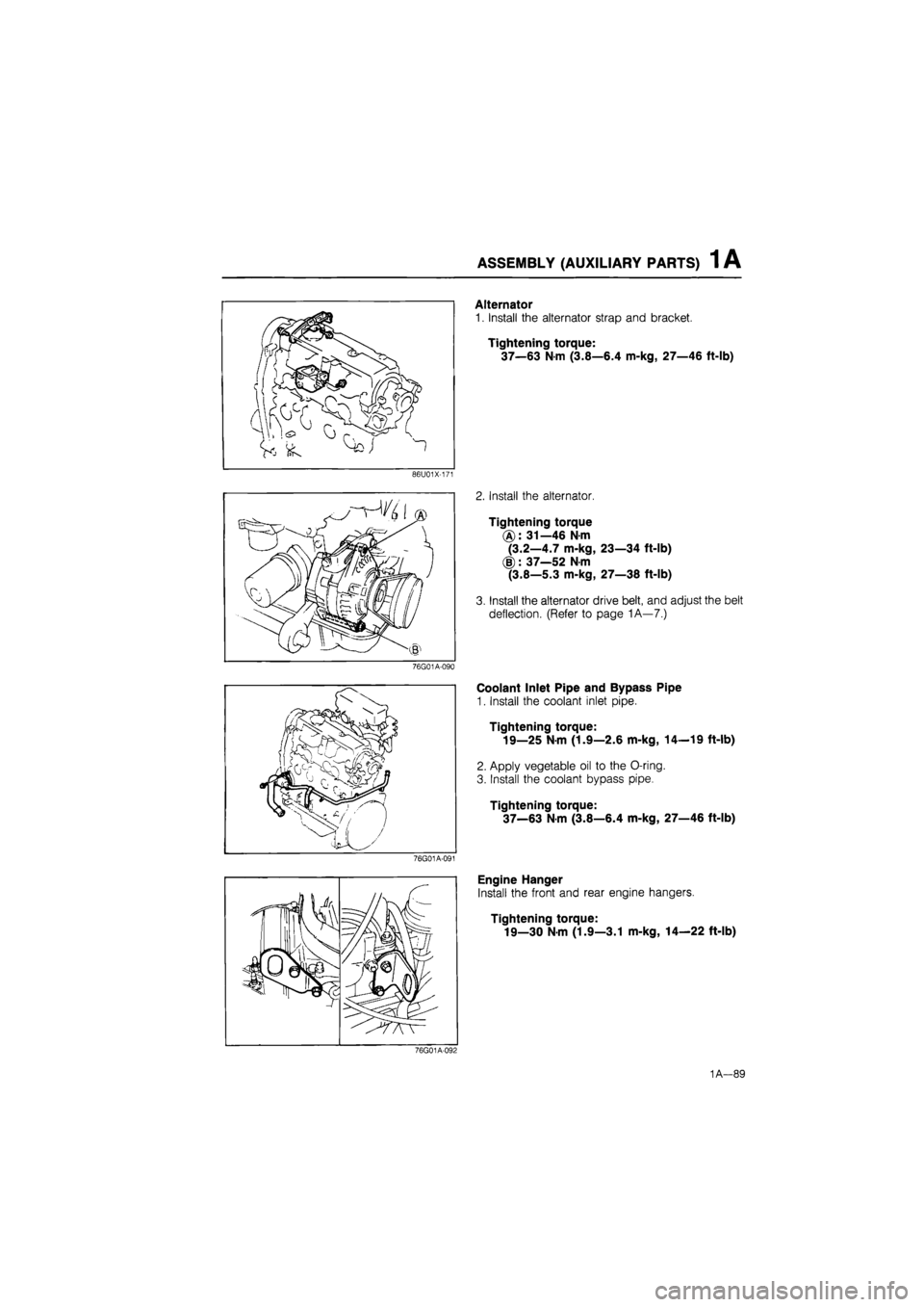
Alternator
1. Install the alternator strap and bracket.
Tightening torque:
37—63 Nm (3.8—6.4 m-kg, 27—46 ft-lb)
2. Install the alternator.
Tightening torque
(A): 31—46 Nm
(3.2—4.7 m-kg, 23—34 ft-lb)
(§): 37—52 N-m
(3.8—5.3 m-kg, 27—38 ft-lb)
3. Install the alternator drive belt, and adjust the belt
deflection. (Refer to page 1A—7.)
Coolant Inlet Pipe and Bypass Pipe
1. Install the coolant inlet pipe.
Tightening torque:
19—25 N-m (1.9—2.6 m-kg, 14—19 ft-lb)
2. Apply vegetable oil to the O-ring.
3. Install the coolant bypass pipe.
Tightening torque:
37—63
N
m (3.8—6.4 m-kg, 27—46 ft-lb)
Engine Hanger
Install the front and rear engine hangers.
Tightening torque:
19—30 N-m (1.9—3.1 m-kg, 14—22 ft-lb)
76G01A-092
1A—89
Page 123 of 1865

INSTALLATION 1A
INSTALLATION
TRANSAXLE ASSEMBLY
Assemble the transaxle to the engine in the sequence shown in the figure referring to the installation note.
37—52 N-m (3.8—5.3 m-kg, 27—38 ft-lb)
8—11 N-m (80-110 cm-kg, 69-95 In-lb) (2)
37—52 N-m (3.8—5.3 m-kg, 27—38 ft-lb) (3.) B9—117 N-m (9.1—11.9 m-kg, 66—86 ft-lb)
76G01A-143
1. Transaxle
2. Clutch under cover
3. Gusset plate
4. Starter
Installation Note
Clutch under cover
Before installation, fill the notches with silicon as
shown in the figure.
76G01A-096
1A—91
Page 124 of 1865

1A INSTALLATION
ENGINE INSTALLATION
Install the engine and transaxle assembly.
Warning: Be sure the vehicle is securely supported.
Torque Specifications
16—27 N-m (1.6—2.8 m-kg, 12—20 ft-lb)
.OT-
9
85—117 N-m (6.7-11.9 m-kg, 63—86 ft-lb)
8—11 N-m (80—110 cm-kg, 69—95 In-lb)
44—64 N-m I (4.5—6.5 m-kg,
_
33-47 ft-lb)
16—27 N-m (1.6—2.8 m-kg, 12—20 ft-lb)
/ 64—89 N-m (6.5—9.1 m-kg, 47—66 ft-lb)
37—52 N-m (3.8—5.3 m-kg, 27—38 ft-lb)
31—46 N-m (3.2-4.7 m-i 23—34 ft-lb)
39—59 N-m _ (4.0—6.0 m-kg, 29—43 ft-lb)
19—25 N-m (1.9—2.6 m-kg, 14—1S ft-lb)
36-54 N-m (3.7—5.5 m-kg, 27—40 ft-lb)
16—23 N-m (1.6—2.3 m-kg, 12—17 ft-lb)
5—7 N-m (50—70 cm-kg, 43—61 In-lb)
-31—46 N-m (3.2—4.7 m-kg, 23—34 ft-lb)
9—13 N m (90—130 cm-kg, 78—113 ft-lb)
29—44 N-m (3.0—4.5 m-kg, 22—33 ft-lb)
8-11 N-m (80—110 cm-kg, 69—95
31—46 N-m (3.2—4.7 m-kg.
8—11 N-m (80
16—23
88—118 N-m (9.0—12.0 m-kg, 65—87 ft-lb)
43—54 N-m (4.4—5.5 m-kg, 32—40 ft-lb)
8—11 N-m (80—110 cm-kg, 69—95 In-lb)
86U01X-180
1A—92
Page 125 of 1865

INSTALLATION 1A
Engine Mount
Install the engine mount.
76G01A-096
86U01X-181
Exhaust Pipe
1. Install the exhaust pipe.
Tightening torque
31—46
N
m
(3.2—4.7 m-kg, 23—34 ft-lb)
(§): 64—89
N
m
(6.5—9.1 m-kg, 47—66 ft-lb)
2. Tighten the bracket bolt.
Tightening torque:
19—25 Nm (1.9—2.6 m-kg, 14—19 ft-lb)
Extension Bar (MTX)
Install the extension bar to the transaxle.
Tightening torque:
31—46
N
m (3.2—4.7 m-kg, 23—34 ft-lb)
Change Rod (MTX)
Install the change rod to the transaxle.
Tightening torque:
16—23 Nm (1.6—2.3 m-kg, 12—17 ft-lb)
1A—93
Page 129 of 1865

INSTALLATION 1A
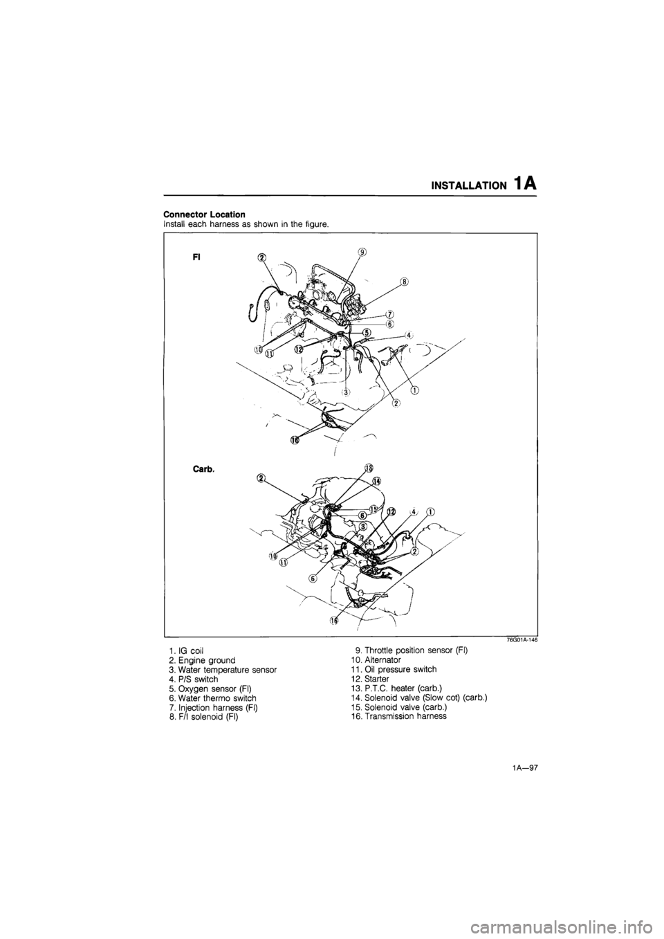
Connector Location
Install each harness as shown in the figure.
1. IG coil
2. Engine ground
3. Water temperature sensor
4. P/S switch
5. Oxygen sensor (Fl)
6. Water thermo switch
7. Injection harness (Fl)
8. F/l solenoid (Fl)
76G01A-146
9. Throttle position sensor (Fl)
10. Alternator
11. Oil pressure switch
12. Starter
13. P.T.C. heater (carb.)
14. Solenoid valve (Slow cot) (carb.)
15. Solenoid valve (carb.)
16. Transmission harness
1A—97
Page 131 of 1865

INSTALLATION 1A
76G01A-099
76G01A-100
Air Cleaner Assembly
1. Install the air cleaner assembly.
Tightening torque:
16—27
N
m (1.6—2.8 m-kg, 12—20 ft-lb)
2. Connect the air flow sensor connector and air in-
take pipe (Fl).
Engine Oil
Add the specified amount and type of engine oil. (Re-
fer to Section 2A.)
Coolant
Close the drain plug, fill the radiator and reservoir tank
with the specified amount and type of coolant. (Re-
fer to Section 3A.)
Check Engine Condition
1. Check for leaks.
2. Perform engine adjustments if necessary.
3. Perform a road test.
4. Recheck the oil and coolant levels.
86U01X-204
1A—99
Page 132 of 1865

1
ENGINE
(DOHC)
OUTLINE 1B— 2
STRUCTURAL VIEW 1B— 2
SPECIFICATIONS 1B— 3
TROUBLESHOOTING GUIDE 1B— 3
TUNE-UP PROCEDURE IB— 5
ON-VEHICLE INSPECTION 1B—10
COMPRESSION 1B—10
ON-VEHICLE MAINTENANCE 1B—11
TIMING BELT 1B—11
CYLINDER HEAD 1B—16
REMOVAL 1B—22
DISASSEMBLY 1B—24
AUXILIARY PARTS 1B—24
TIMING BELT 1B—26
CYLINDER HEAD 1B—28
CYLINDER BLOCK 1B—30
INSPECTION AND REPAIR 1B—34
ASSEMBLY 1B—48
CYLINDER BLOCK 1B—48
CYLINDER HEAD 1B—59
TIMING BELT 1B—64
AUXILIARY PARTS 1B—68
INSTALLATION 1B—73
TRANSAXLE ASSEMBLY 1B—73
ENGINE INSTALLATION 1B—74
76G01B-001
Page 134 of 1865

TROUBLESHOOTING GUIDE 1 B
SPECIFICATIONS
Engine model FE DOHC
Item Leaded fuel Unleaded fuel
Type Gasoline, 4 cycle
Cylinder arrangement and number In line, 4 cylinders
Combustion chamber Pentroof
Valve system OHC, belt driven
Displacement cc (cu in) 1,998 (121.9)
Bore and stroke mm (in) 86.0 x 86.0 (3.39 x 3.39)
Compression ratio 10.0 : 1 9.2 : 1
Compression pressure Standard 1,422 (14.5, 206)—290 1,373 (14.0, 199)—310
kPa (kg/cm2, psi)-rpm Minimum 996 (10.2, 144)—290 961 (9.8, 139)—310
IN Open BTDC 10° 10°
Valve timing
IN Close ABDC 60° 55° Valve timing
EX Open BBDC 60° 55° EX Close ATDC 10° 10°
Valve clearance mm (in) IN 0; Maintenance-free Valve clearance mm (in) EX 0; Maintenance-free
Idle speed rpm 750 ± 50
Ignition timing BTDC 12° ± 1°
Firing order 1—3--4-2
76G01B-002
TROUBLESHOOTING GUIDE
Problem Possible Cause Remedy Page
Difficult starting Malfunction of engine-related components
Burned valve
Worn piston, piston ring, or cylinder
Failed cylinder head gasket
Replace
Replace or repair Replace
1B—35 1B—43 1B—16
Malfunction of fuel system Refer to Section 4C
Malfunction of electrical system Refer to Section 5
Poor Idling Malfunction of engine-related components Malfunction of HLA
Poor valve to valve seat contact
Failed cylinder head gasket
Replace
Repair or replace
Replace
1B—60 1B—37 1B—16
Malfunction of fuel system Refer to Section 4C
Excessive oil
consumption Oil working up Worn piston ring groove or sticking piston ring Worn piston or cylinder
Replace
Replace or repair
1B-43 1B-43
Oil working down
Worn valve seal
Worn valve stem or guide
Replace
Replace 1B-35
Oil leakage Refer to Section 2A
76G01B-003
1B—3