lock MAZDA 626 1987 Workshop Manual
[x] Cancel search | Manufacturer: MAZDA, Model Year: 1987, Model line: 626, Model: MAZDA 626 1987Pages: 1865, PDF Size: 94.35 MB
Page 1468 of 1865

1 1 ANTI-LOCK BRAKE SYSTEM (ABS)
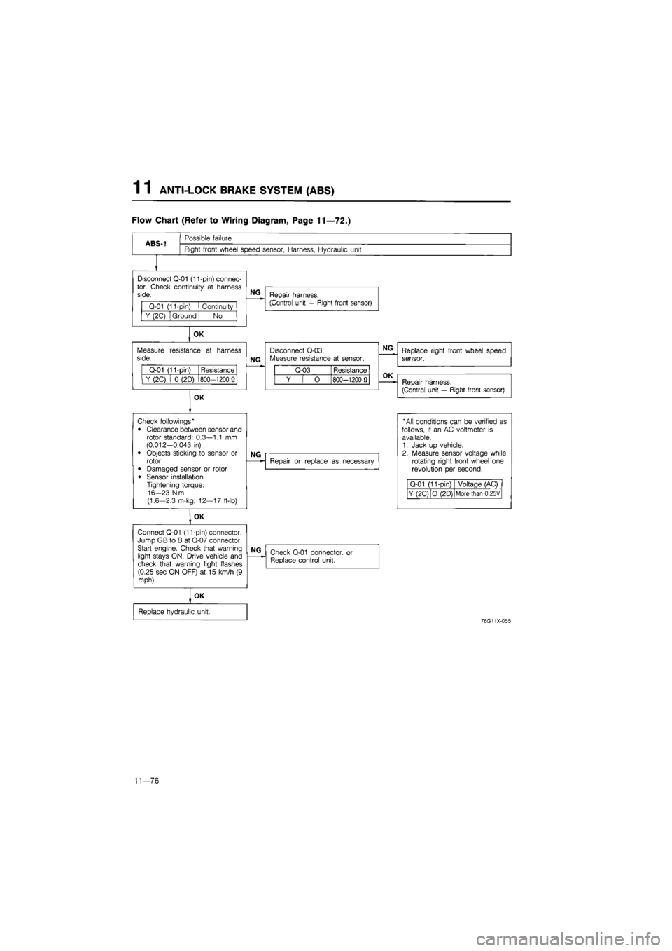
Flow Chart (Refer to Wiring Diagram, Page 11—72.)
ABS-1
Possible failure
Right front wheel speed sensor, Harness, Hydraulic unit
Disconnect Q-01 (11-pin) connec-tor. Check continuity
at
harness side.
Q-01 (11-pin)
I
Continuity
Y (2C) Ground No
OK
Measure resistance
at
harness side.
Q-01 (11-pin) Resistance
Y (2C)
i 0
(2D) 800—1200
Q
OK
NG
Repair harness.
(Control unit — Right front sensor)
NG
Disconnect Q-03. Measure resistance
at
sensor.
Q-03 Resistance
Y
[ O
800—1200 Q
NG
Replace right front wheel speed sensor.
OK
Repair harness.
(Control unit — Right front sensor)
Check followings*
• Clearance between sensor and rotor standard: 0.3—1.1
mm
(0.012-0.043
in)
• Objects sticking
to
sensor
or
rotor
• Damaged sensor
or
rotor
• Sensor installation Tightening torque: 16-23 N-m (1.6-2.3 m-kg, 12—17 ft-lb)
OK
Connect Q-01 (11-pin) connector. Jump GB
to B at
Q-07 connector. Start engine. Check that warning light stays ON. Drive vehicle and check that warning light flashes (0.25 sec ON OFF)
at 15
km/h
(9
mph).
NG
Repair
or
replace
as
necessary
* All conditions can
be
verified
as
follows,
if an AC
voltmeter
is
available. 1. Jack
up
vehicle. 2. Measure sensor voltage while rotating right front wheel
one
revolution
per
second.
Q-01 (11-Din) Voltage (AC)
Y (2C) O (2D) More than 0.25V
NG
Check Q-01 connector,
or
Replace control unit.
OK
Replace hydraulic unit.
76G11X-055
11—76
Page 1469 of 1865

ANTI-LOCK BRAKE SYSTEM (ABS) 1 1
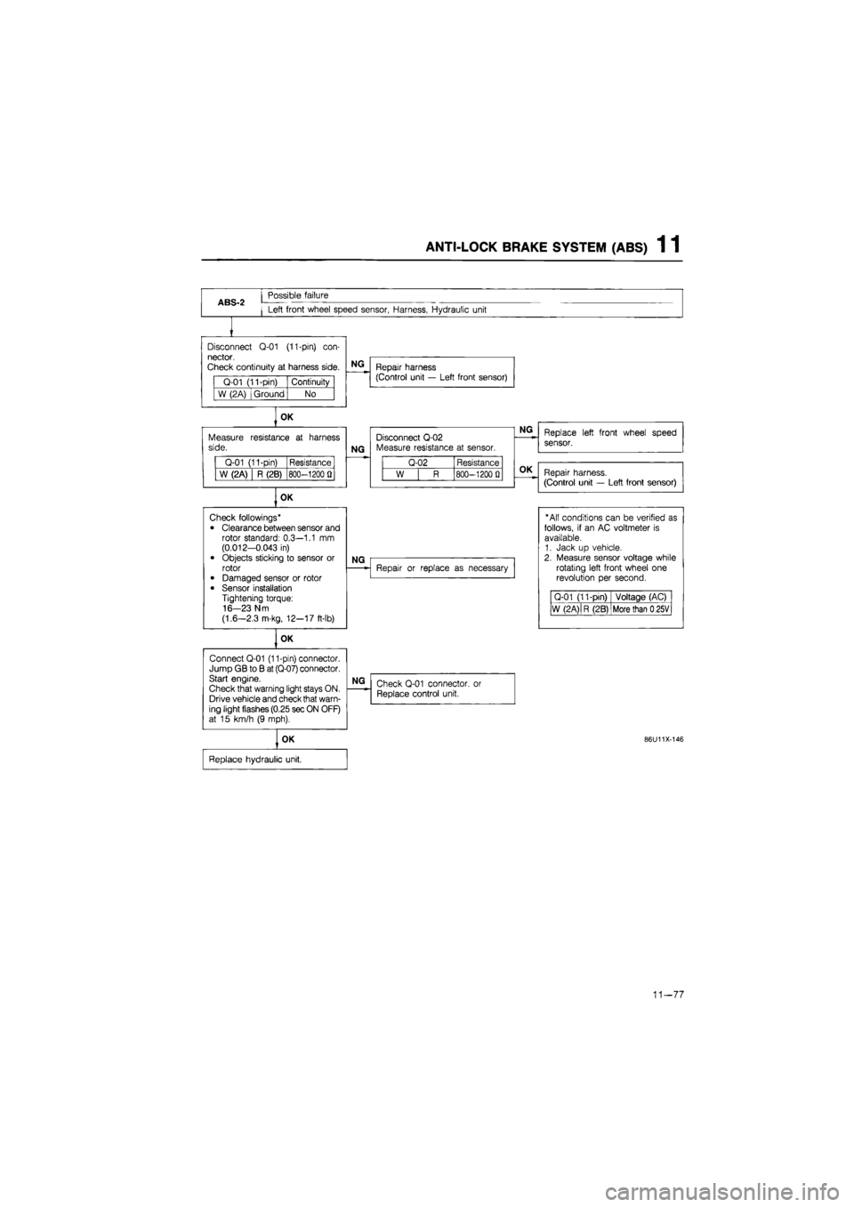
ABS-2
Possible failure
Left front wheel speed sensor, Harness, Hydraulic unit
Disconnect
Q-01
(11-pin)
con-
nector.
Check continuity
at
harness side.
Q-01 (11-pin) Continuity
W (2A) Ground No
OK
Measure side.
Q-01 (11-pin) Resistance
W (2A) R (2B) 800-1200
fl
OK
Connect Q-01 (11-pin) connector. Jump GB
to B
at (Q-07) connector. Start engine.
Check that warning light stays ON. Drive vehicle and check that warn-ing light flashes (0.25 sec ON OFF) at
15
km/h
(9
mph).
NG
Repair harness (Control unit
—
Left front sensor)
resistance
at
harness
NG
Disconnect Q-02 Measure resistance
at
sensor.
Q-02 Resistance
W
| R
800-1200
0
OK
Check followings*
• Clearance between sensor and rotor standard: 0.3—1.1
mm
(0.012-0.043
in)
• Objects sticking
to
sensor
or
rotor • Damaged sensor
or
rotor
• Sensor installation Tightening torque: 16-23 N m
(1.6—2.3 m-kg, 12-17 ft-lb)
NG
OK
NG
Repair
or
replace
as
necessary
NG
Check Q-01 connector,
or
Replace control unit.
OK
Replace hydraulic unit.
Replace left front wheel speed
sensor.
Repair harness.
(Control unit
—
Left front sensor)
"All conditions can
be
verified
as
follows,
if an AC
voltmeter
is
available. 1. Jack
up
vehicle. 2. Measure sensor voltage while rotating left front wheel
one
revolution
per
second.
Q-01 (11-pin) Voltage (AC)
W (2 A)
|
R (2B) More than
0
25V
86U11X-146
11-77
Page 1470 of 1865

1 1 ANTI-LOCK BRAKE SYSTEM (ABS)
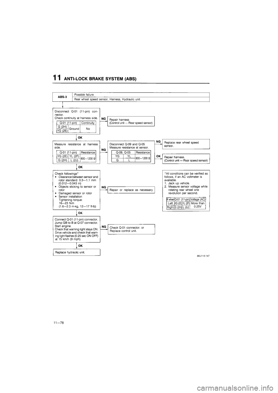
ABS-3
Possible failure
Rear wheel speed sensor, Harness, Hydraulic unit
Disconnect
Q-01
(11-pin)
con-
nector.
Check continuity
at
harness side.
Q-01 (11-pin) Continuity
G (2H) Ground No YG (2E) Ground No
Measure side.
Q-01 (11-pin) Resistance
YG (2E) YL (2F) 800—1200
fi
G (2H)
] L
(2J) 800—1200
fi
OK
Connect Q-01 (11-pin) connector. Jump GB
to B at
Q-07 connector. Start engine.
Check that warning light stays ON. Drive vehicle and check that warn-ing light flashes (0.25 sec ON OFF) at
15
km/h
(9
mph).
NG
Repair harness (Control unit
—
Rear speed sensor)
OK
resistance
at
harness
NG
Disconnect Q-09 and Q-05 Measure resistance
at
sensor.
Q-09, Q-05 Resistance
YG YL 800-1200
0
G L 800-1200
0
OK
Check followings* • Clearance between sensor and rotor standard: 0.3—1.1
mm
(0.012-0.043
in)
• Objects sticking
to
sensor
or
rotor
• Damaged sensor
or
rotor
• Sensor installation Tightening torque: 16-23 N-m
(1.6—2.3 m-kg, 12—17 ft-lb)
NG
Repair
or
replace
as
necessary
NG
Check Q-01 connector. Replace control unit.
or
OK
Replace hydraulic unit,
Replace rear wheel speed
sensor.
OK
Repair harness.
(Control unit
—
Rear speed sensor)
* All conditions can
be
verified
as
follows,
if an AC
voltmeter
is
available. 1. Jack
up
vehicle. 2. Measure sensor voltage while rotating rear wheel
one
revolution
per
second.
fi
wheel Q-01 (11-pin) Voltaqe (AC)
Left |YG (2E) YL (2F) More than 0.25V Right G (2H) L(2J)
More than 0.25V
86U11X-147
11-78
Page 1471 of 1865

ANTI-LOCK BRAKE SYSTEM (ABS) 1 1
86U11X-148
86U11X-149
86U11X-150
86U11X-151
11-79
Page 1472 of 1865

1 1 ANTI-LOCK BRAKE SYSTEM (ABS)
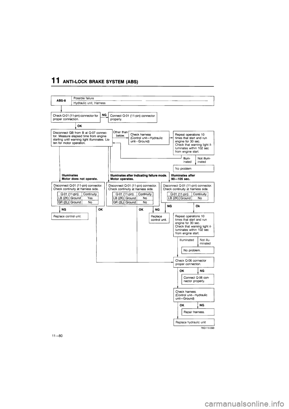
ABS-8
Possible failure
ABS-8
Hydraulic unit, Harness
Check Q-01 (11-pin) connector for
proper connection.
NG
Connect Q-01 (11-pin) connector
properly.
OK
Disconnect
GB
from
B at
Q-07 connec-tor. Measure elapsed time from engine starting until warning light illuminates.
Lis-
ten
for
motor operation.
Other than
below. Check harness (Control unit—Hydraulic unit—Ground)
Repeat operations
10
times that start and
run
engine
for 30
sec. Check that warning light
i
luminates within 102 sec from engine start.
Illum-
inated
Not illum-inated
No problem
Illuminates Motor does not operate.
Disconnect Q-01 (11-pin) connector.
Check continuity
at
harness side.
Q-01 (11-pin) Continuity
LB (2K) Ground Yes
GR (2L) Ground
| No
NG
Replace control unit.
OK
Illuminates after indicating failure mode.
Motor operates.
Disconnect Q-01 (11-pin) connector. Check continuity
at
harness side.
Q-01 (11-pin) Continuity
LB (2K) Ground No
GR (2L) Ground No
OK
Illuminates after
90—105 sec.
Disconnect Q-01 (11-pin) connector.
Check continuity
at
harness side.
Q-01 (11-pin) Continuity
LB (2K) Ground No
NG
NG
Replace control unit.
Ok
Repeat operations
10
times that start and
run
engine
for 30
sec. Check that warning light
il-
luminates within 102 sec from engine start.
Illuminated Not illu-
minated
No problem.
Check Q-06 connector proper connection.
76G11X-093
11-80
Page 1473 of 1865

ANTI-LOCK BRAKE SYSTEM (ABS) 1 1
ABS-9
Possible failure
Relay box, Hydraulic unit, Harness
Disconnect Q-01 (17-pin) connector. Disconnect battery. Turn ignition switch
ON.
Check continuity
at
harness side.
Q-01 (17-pin) Continuity
RY (B) BG (G) No
NG
OK
Check that resistance between
LO
(C)
of
harness side
and
ground changes when reversing
© and
© test-leads.
NG
Check relay box. (Refer
to
page 11—87.)
OK
Repair harness.
(Control unit—Relay box-Hydraulic unit)
NG
Replace relay box.
OK
Check continuity
at
harness side.
Q-01 (17-pin) Continuity
RY (B) Ground Yes
OK
Relay control unit.
NG
Disconnect Q-09 connector. Check continuity
at
motor side.
Q-09 Continuity
RY Ground Yes
NG
Repair harness. (Motor—Ground)
OK
Check continuity
at
motor side.
Q-09 Continuity
RY B Yes
NG
Replace hydraulic unit.
OK
Repair harness. (Control unit—Relay box-Hydraulic unit)
76G11X-056
11-81
Page 1474 of 1865

1 1 ANTI-LOCK BRAKE SYSTEM (ABS)
86U11X-154
ABS-11
Possible failure
Relay box, Hydraulic unit, Harness
Disconnect Q-01 (17-pin) connector. Disconnect battery. Check continuity
at
harness side.
Q-01 (17-pin) Continuity
LO(C) BG (G) No
OK
Q-01 (17-pin) Resistance
BL (E) Ground Aoorox. 7512
OK
Replace control unit.
Check resistance
at
harness side.
NG
Check relay box. (Refer
to
page 11—87.)
OK
Repair harness. (Control unit—Relay box-Hydraulic unit)
NG
Q-08 Continuitv
BL Ground No
OK
Repair harness. (Control unit—Relay box-Hydraulic unit)
NG
Replace relay box.
Disconnect Q-08 connector. Check continuity
at
relay side.
NG
76G11X-057
86U11X-156
11-82
Page 1475 of 1865

ANTI-LOCK BRAKE SYSTEM (ABS) 1 1
ABS-13
Possible failure
Relay box, Hydraulic unit, Harness
Check Q-10, Q-06, and Q-08 con-
nectors
for
proper connection.
OK
Q-01 (17-pin) Resistance
BL (E) BG (G) approx. 75
Q
OK
Q-01 (17-pin) Resistance
LO (C) © probe YG(J) © probe approx.
65 Q
Q-08 (6-pin) Q-08 (2-Din) Continuity
BG LR Yes
OK
Disconnect Q-09 and Q-08 (2-pin) connectors. Check continuity
at
harness side.
Q-09 Q-08 (2-pin) Continuity
RY RY Yes
Q-09 Continuity
RY I Ground No
Q-09 Resistance
RY B approx. 0.1
Si
NG
Disconnect Q-01 (17-pin) connector. Disconnect battery. Measure resistance at harness side.
NG
Check resistance between BL (C)
and
YG
(J)
of
harness side.
OK
Check continuity
at
hydraulic unit side.
NG
OK
Turn ignition switch ON.
Check continuity
at
harness side.
Repair connector.
Check relay box. (Refer
to
page 11 —87)
NG
Replace relay box.
OK
Repair harness.
(Control unit—Relay box
or
Ignition switch—Hydraulic unit)
NG
Repair harness. (Relay box—Battery)
NG
Repair harness. (Hydraulic unit—Relay box)
NG
OK
Replace hydraulic unit
Check relay box. (Refer
to
page 11—87.)
OK
Replace control unit.
NG
Replace relay box
76G11X-058
11-83
Page 1476 of 1865

1 1 ANTI-LOCK BRAKE SYSTEM (ABS)
ABS-15
Possible failure
Control unit, Harness, Hydraulic unit
Disconnect Q-10 and Q-01 (17-pin and 11-pin) connectors. Check continuity
at
hydraulic unit side.
Q-10 Continuity
BR
|
Ground No
OK
Disconnect Q-06 connector.
Check continuity
at
hydraulic side.
Q-10 Continuity
BR Ground No
Q-06 Q-10 Resistance
Br
BW L
YG BR approx.
3 J)
YR YW
NG
NG
OK
Check Q-06 connector for proper connection.
| OK
Disconnect Q-06 connector. Meas-ure resistance
at
hydraulic unit side.
OK
NG
Replace hydraulic unit.
Repair harness. (Hydraulic unit-Control unit)
Replace hydraulic unit.
NG
Repair Q-06 connector.
Connect
Q-06 and Q-10 con-
nectors.
Check continuity
at
harness side.
Q-01 (17-pin) Continuity
Br (K) BW (0) L(R) YG(J) YR (M) YW (Q)
LO (C)
Yes
(Less than
100 Q)
NG
Repair harness.
(Control unit—Hydraulic unit)
OK
Replace control unit.
76G11X-095
11—84
Page 1477 of 1865

ANTI-LOCK BRAKE SYSTEM
(ABS) 1 1
ABS-16
Possible failure
Control unit, Harness
Disconnect Q-01 (17-pin) and Q-10 connectors.
Check that hydraulic unit and har-ness resistance does not fluctuate when moving harness.
Q-01 17-pin) Q-10 Resistance
Br (K) BW
(0)
L(R) YG(J) YR (M) YW (Q)
BR Must
be
constant
NG
Repair connector
or
harness. (Q-01 (17-pin), Q-10)
OK
Replace control unit.
86U11X-160
ABS-17
Possible failure
ABS-17
Control unit
Replace control unit.
ABS-18
Possible failure
ABS-18
Control unit
Replace control unit.
86U11X-161
11-85