lock MAZDA 626 1987 Workshop Manual
[x] Cancel search | Manufacturer: MAZDA, Model Year: 1987, Model line: 626, Model: MAZDA 626 1987Pages: 1865, PDF Size: 94.35 MB
Page 1721 of 1865

15 POWER WINDOW
OK Check power window switch
on
each door. Refer
to
page 15—67.
76G15X-059
INSPECTION
Power Window Driver's Side Switch
(For Sedan and Hatchback)
Check for continuity between terminals of the switch.
Main switch
—Terminal Position -——___ h i
Lock
Unlock
O o
O O:
Indicates continuity
76G15X-016
c f i i 0
b e h k n
a d R J m /
O O:
Indicates continuity
15-66
Page 1722 of 1865

REAR WINDOW 15
9 c a
CD [=• cm
•
h f d b
76G15X-017
g c a
I I I I
cm I I I I
h f d b
86U15X-11E
(For Coupe/MX-6)
Check for continuity between terminals of the switch.
Main switch
-—-—^^Terminal Position
——- ^
a c
Lock
Unlock 0 O
o
-O: Indicates continuity
Switch
'erminal
Position
UP
OFF
DOWN
Driver's side
O
O
o
o-
o
-o
-o
-o
=o
-o
Passenger's side
O
O
O-
O
O
-o
-o
-o
-o
-o
O O:
Indicates continuity
Switch on Each Side
(For Sedan And Hatchback)
Check for continuity between terminals of the switch.
Position Terminal
UP
OFF
DOWN
O-
O-
O-
-0
O-
O-
-o
-o -o
-o
O O:
Indicates continuity
(For Coupe/MX-6)
Check for continuity between terminals of the switch.
Position
~———^
a b d f h
UP O—
O— —0
—o
OFF o—
O—
—o —O
DOWN O—
o—
—0 —o
O
O:
Indicates continuity
76G15X-019
15-67
Page 1740 of 1865

CRUISE CONTROL SYSTEM 1 5
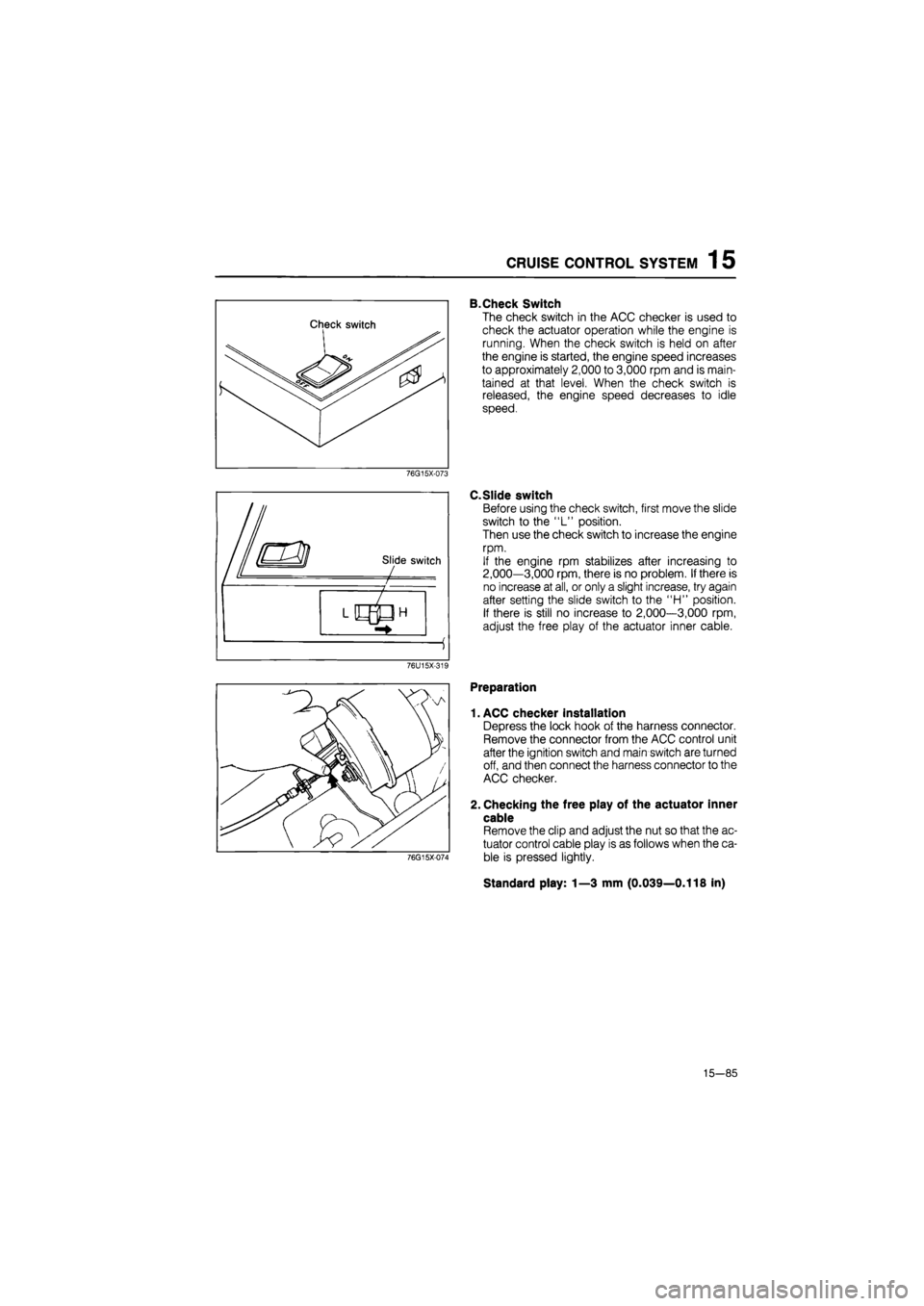
B.Check Switch
The check switch in the ACC checker is used to
check the actuator operation while the engine is
running. When the check switch is held on after
the engine is started, the engine speed increases
to approximately 2,000 to 3,000 rpm and is main-
tained at that level. When the check switch is
released, the engine speed decreases to idle
speed.
76G15X-073
C.Slide switch
Before using the check switch, first move the slide
switch to the "L" position.
Then use the check switch to increase the engine
rpm.
If the engine rpm stabilizes after increasing to
2,000—3,000 rpm, there is no problem. If there is
no increase at all, or only a slight increase, try again
after setting the slide switch to the "H" position.
If there is still no increase to 2,000—3,000 rpm,
adjust the free play of the actuator inner cable.
76U15X-319
76G15X-074
Preparation
1. ACC checker installation
Depress the lock hook of the harness connector.
Remove the connector from the ACC control unit
after the ignition switch and main switch are turned
off, and then connect the harness connector to the
ACC checker.
2. Checking the free play of the actuator inner
cable
Remove the clip and adjust the nut so that the ac-
tuator control cable play is as follows when the ca-
ble is pressed lightly.
Standard play: 1—3 mm (0.039—0.118 in)
15—85
Page 1750 of 1865

AUTO ADJUSTING SUSPENSION (AAS) 1 5
Checking Condition
Note:
Turn the ignition switch OFF to reset the con-
trol unit before each test.
Condition A
1. Turn the ignition switch ON.
2. Set steering wheel in the straight-ahead position,
and check the output pattern.
86U15X-154
Condition B
1. Turn the ignition switch ON.
2. Turn the steering wheel right and left, and check
the output pattern.
86U15X-155
•
/
AUTO ADJUSTING SUSPENSION I- AUTO—i SOFT NORMAL SPORT
Condition C
1. Turn the ignition switch ON.
2. Change the AAS switch from NORMAL to SPORT
or from SPORT to NORMAL, and check the out-
put pattern.
86U15X-156
Condition D
1. Operate the vehicle on a chassis roller.
2. Check the output pattern at above 15 km/h (9.3
mph).
Caution
a) Block the rear wheels.
b) In vehicle equipped with ABS, ABS warn-
ing light may come on, which is not a fail-
ure. The light goes off by turning ignition
switch OFF and again ON.
86U15X-157
15—95
Page 1760 of 1865

POWER DOOR LOCK 1 5
POWER DOOR LOCK
STRUCTURAL VIEW
CIRCUIT DIAGRAM
BATTERY
86U15X-171
15—105
Page 1761 of 1865

1 5 POWER DOOR LOCK
TROUBLESHOOTING
Terminal Voltage
WG 12V
B OV
Check the voltage
at GB
terminal
of
the power door lock relay with each switch condition.
Terminal Condition Voltage
GB Lock 12V GB Unlock OV
OK
Check the voltage
at R
and
G
terminal
of
the power door lock relay with each switch condition.
Terminal Condition Voltaae
R Lock OV R Unlock 12V
G Lock 12V G Unlock OV
Power door lock does not operate.
Check DOOR LOCK 30A fuse.
OK
NG
Short circuit.
Check the voltage
at
each terminal
of
the power door lock relay connector.
NG
Repair the harness. (Fuse box
to
relay, Relay
to
ground)
OK
Check the power door lock switch. Refer
to
page 15-107.
OK
NG
Replace the switch.
NG
Repair the harness. (Door lock switch
to
relay)
NG
Replace the door lock relay.
OK
Check the power door lock motor. Refer
to
page
15-107.
OK
Repair the harness. (Relay
to
each motors)
NG
Replace the door lock motor.
76G15X086
15—106
Page 1762 of 1865

POWER DOOR LOCK 1 5
86U15X-173
INSPECTION
Power Door Lock Switch
1. Check for continuity of the switch with an
ohmmeter.
WG GB B
Lock
o O
Unlock
o O
O
O:
indicates continuity
2. If continuity is not as specified, replace the switch.
Power Door Lock Motor
1. Check operation of the door lock actuator when
the battery voltage is applied to the terminal.
Connecting
to
Door lock motor 12V ground Door lock motor
G R LOCK (Pull)
R G UNLOCK (Release)
2. If not, replace the door lock motor.
86U15X-174
15—107
Page 1793 of 1865

16 OUTLINE
Safety Precautions
1. The R-12 liquid refrigerant is highly volatile. A drop
of it on the skin of your hand could result in local-
ized frostbite. When handling the refrigerant, be
sure to wear gloves.
2. If the refrigerant splashes into your eyes, wash
them with clean water immediately. It is standard
practice to wear goggles or glasses to protect your
eyes, and gloves to protect your hands.
3. The R-12 container is a highly pressurized vessel.
Never leave it in a hot place, and check to be sure
that the temperature where it is stored is below
52°C (126°F).
4. A halide leak detector is often used to check the
system for refrigerant leakage. Remember that
R-12, upon coming into contact with flame (this de-
tector burns like propane to produce a small flame),
produces phosgene, a toxic gas.
69G16X020
V/^V
Connection
LZl
jvmi
Refrigerant Container Service Valve
1. Before connecting the valve to the refrigerant con-
tainer, turn the handle fully counterclockwise.
2. Turn the disc counterclockwise until it reaches its
highest position.
3. Connect the center hose to the valve fitting. Turn
the disc fully clockwise by hand.
4. Turn the handle clockwise to make a hole in the
sealed tap.
5. Turn the handle fully counterclockwise to fill the
center hose with air. Do not open the high- and
low-pressure manual valves.
6. Loosen the center hose nut connected to the cen-
ter fitting of the manifold gauge.
Allow air to escape for a few seconds, then tight-
en the nut.
69G16X-021
16-10
Page 1807 of 1865

16 CONDENSER
CONDENSER
ON-VEHICLE INSPECTION
1. Check the condenser fins for blockage or damage.
If the fins are clogged, clean them with compressed air.
If the fins are bent, straighten them with a screwdriver or pair of pliers.
2. Check the condenser fittings for leakage.
Repair or replace, if necessary.
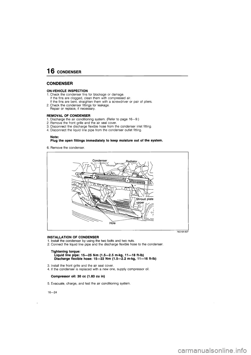
REMOVAL OF CONDENSER
1. Discharge the air conditioning system. (Refer to page 16—9.)
2. Remove the front grille and the air seal cover.
3. Disconnect the discharge flexible hose from the condenser inlet fitting.
4. Disconnect the liquid line pipe from the condenser outlet fitting.
Note:
Plug the open fittings immediately to keep moisture out of the system.
6. Remove the condenser.
Condenser Radiator
Hole
76G16X-637
INSTALLATION OF CONDENSER
1. Install the condenser by using the two bolts and two nuts.
2. Connect the liquid line pipe and the discharge flexible hose to the condenser.
Tightening torque:
Liquid line pipe: 15—25 Nm (1.5—2.5 m-kg, 11—18 ft-lb)
Discharge flexible hose: 15—22 N-m (1.5—2.2 m-kg, 11—16 ft-lb)
3. Install the front grille and the air seal cover.
4. If the condenser is replaced with a new one, supply compressor oil.
Compressor oil: 30 cc (1.83 cu in)
5. Evacuate, charge, and test the air conditioning system.
16—24
Page 1810 of 1865

COOLING UNIT 1 6
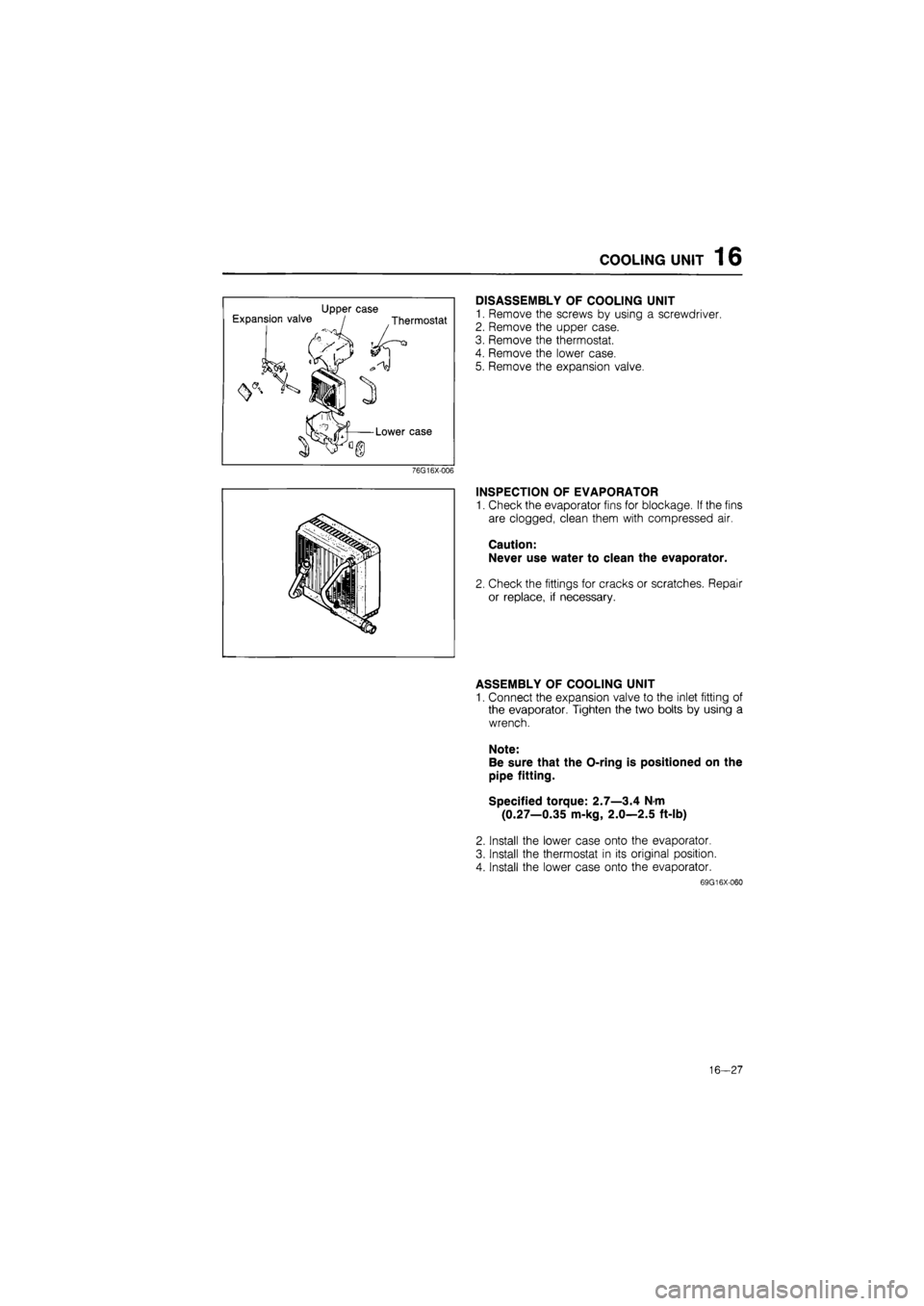
Upper case Expansion valve / Thermostat
Lower case
76G16X-006
DISASSEMBLY OF COOLING UNIT
1. Remove the screws by using a screwdriver.
2. Remove the upper case.
3. Remove the thermostat.
4. Remove the lower case.
5. Remove the expansion valve.
INSPECTION OF EVAPORATOR
1. Check the evaporator fins for blockage. If the fins
are clogged, clean them with compressed air.
Caution:
Never use water to clean the evaporator.
2. Check the fittings for cracks or scratches. Repair
or replace, if necessary.
ASSEMBLY OF COOLING UNIT
1. Connect the expansion valve to the inlet fitting of
the evaporator. Tighten the two bolts by using a
wrench.
Note:
Be sure that the O-ring is positioned on the
pipe fitting.
Specified torque: 2.7—3.4 N-m
(0.27—0.35 m-kg, 2.0—2.5 ft-lb)
2. Install the lower case onto the evaporator.
3. Install the thermostat in its original position.
4. Install the lower case onto the evaporator.
69G16X-060
16—27