timing belt MAZDA 626 1987 Owner's Guide
[x] Cancel search | Manufacturer: MAZDA, Model Year: 1987, Model line: 626, Model: MAZDA 626 1987Pages: 1865, PDF Size: 94.35 MB
Page 117 of 1865

ASSEMBLY (TIMING BELT) 1A
6. Check the timing belt deflection. If the deflection
is not correct, loosen the tensioner lock bolt and
repeat steps 3—5 above. Replace the tensioner
spring if necessary.
Belt deflection:
FE: 5.5—6.5 mm (0.22—0.26 in)
F8, F6: 4.0—5.0 mm (0.16—0.20 in)
/98 N (10kg, 22 lb)
76G01A-086
Baffle Plate
Position the baffle plate on the timing belt pulley.
Timing Belt Cover
Install the lower timing belt cover, upper timing belt
cover, and new gaskets.
Tightening torque:
7—10 Nm (70—100 cm-kg, 61—87 in-lb)
86U01X-163
Crankshaft Pulley
Install the crankshaft pulley.
Tightening torque: 12—17 N-m
(1.25—1.75 m-kg, 109—152 in-lb)
69G01B-170
76G01A-142
Valve Clearance (8-valve)
Adjust the valve clearance. (Refer to page
1
A—10.)
Cylinder Head Cover
1. Apply silicon sealant to the shaded areas shown
in the figure.
2. Install the cylinder head cover.
Tightening torque:
6—8 N-m (60—80 cm-kg, 52—69 in-lb)
1A—85
Page 132 of 1865

1
ENGINE
(DOHC)
OUTLINE 1B— 2
STRUCTURAL VIEW 1B— 2
SPECIFICATIONS 1B— 3
TROUBLESHOOTING GUIDE 1B— 3
TUNE-UP PROCEDURE IB— 5
ON-VEHICLE INSPECTION 1B—10
COMPRESSION 1B—10
ON-VEHICLE MAINTENANCE 1B—11
TIMING BELT 1B—11
CYLINDER HEAD 1B—16
REMOVAL 1B—22
DISASSEMBLY 1B—24
AUXILIARY PARTS 1B—24
TIMING BELT 1B—26
CYLINDER HEAD 1B—28
CYLINDER BLOCK 1B—30
INSPECTION AND REPAIR 1B—34
ASSEMBLY 1B—48
CYLINDER BLOCK 1B—48
CYLINDER HEAD 1B—59
TIMING BELT 1B—64
AUXILIARY PARTS 1B—68
INSTALLATION 1B—73
TRANSAXLE ASSEMBLY 1B—73
ENGINE INSTALLATION 1B—74
76G01B-001
Page 134 of 1865

TROUBLESHOOTING GUIDE 1 B
SPECIFICATIONS
Engine model FE DOHC
Item Leaded fuel Unleaded fuel
Type Gasoline, 4 cycle
Cylinder arrangement and number In line, 4 cylinders
Combustion chamber Pentroof
Valve system OHC, belt driven
Displacement cc (cu in) 1,998 (121.9)
Bore and stroke mm (in) 86.0 x 86.0 (3.39 x 3.39)
Compression ratio 10.0 : 1 9.2 : 1
Compression pressure Standard 1,422 (14.5, 206)—290 1,373 (14.0, 199)—310
kPa (kg/cm2, psi)-rpm Minimum 996 (10.2, 144)—290 961 (9.8, 139)—310
IN Open BTDC 10° 10°
Valve timing
IN Close ABDC 60° 55° Valve timing
EX Open BBDC 60° 55° EX Close ATDC 10° 10°
Valve clearance mm (in) IN 0; Maintenance-free Valve clearance mm (in) EX 0; Maintenance-free
Idle speed rpm 750 ± 50
Ignition timing BTDC 12° ± 1°
Firing order 1—3--4-2
76G01B-002
TROUBLESHOOTING GUIDE
Problem Possible Cause Remedy Page
Difficult starting Malfunction of engine-related components
Burned valve
Worn piston, piston ring, or cylinder
Failed cylinder head gasket
Replace
Replace or repair Replace
1B—35 1B—43 1B—16
Malfunction of fuel system Refer to Section 4C
Malfunction of electrical system Refer to Section 5
Poor Idling Malfunction of engine-related components Malfunction of HLA
Poor valve to valve seat contact
Failed cylinder head gasket
Replace
Repair or replace
Replace
1B—60 1B—37 1B—16
Malfunction of fuel system Refer to Section 4C
Excessive oil
consumption Oil working up Worn piston ring groove or sticking piston ring Worn piston or cylinder
Replace
Replace or repair
1B-43 1B-43
Oil working down
Worn valve seal
Worn valve stem or guide
Replace
Replace 1B-35
Oil leakage Refer to Section 2A
76G01B-003
1B—3
Page 135 of 1865

TROUBLESHOOTING GUIDE 1 B
Problem Possible Cause Remedy Page
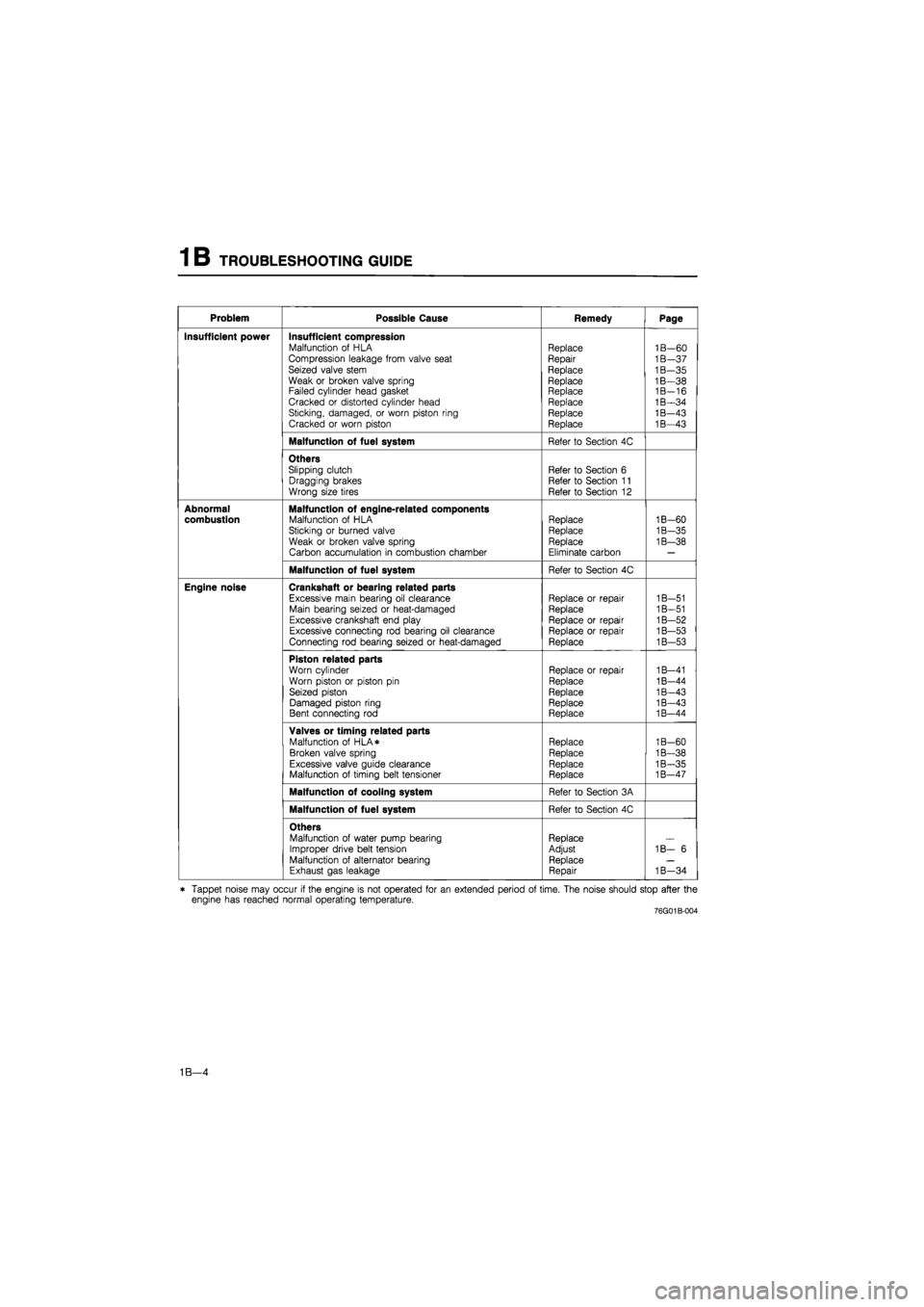
Insufficient power Insufficient compression Malfunction of HLA Compression leakage from valve seat Seized valve stem Weak or broken valve spring Failed cylinder head gasket Cracked or distorted cylinder head Sticking, damaged, or worn piston ring Cracked or worn piston
Replace Repair
Replace
Replace Replace Replace Replace Replace
1B—60 1B—37 1B—35 1B—38 1B-16 1B—34 1B—43 1B—43
Malfunction of fuel system Refer to Section 4C
Others Slipping clutch Dragging brakes Wrong size tires
Refer to Section 6 Refer to Section 11 Refer to Section 12
Abnormal combustion Malfunction of engine-related components Malfunction of HLA Sticking or burned valve
Weak or broken valve spring Carbon accumulation in combustion chamber
Replace Replace Replace
Eliminate carbon
1B-60
1B-35
1B—38
Malfunction of fuel system Refer to Section 4C
Engine noise Crankshaft or bearing related parts
Excessive main bearing oil clearance Main bearing seized or heat-damaged Excessive crankshaft end play Excessive connecting rod bearing oil clearance Connecting rod bearing seized or heat-damaged
Replace or repair Replace
Replace or repair Replace or repair Replace
1B-51 1B—51 1B—52 1B—53 1B—53
Piston related parts
Worn cylinder Worn piston or piston pin Seized piston Damaged piston ring Bent connecting rod
Replace or repair
Replace
Replace Replace Replace
1B—41 1B-44 1B—43 1B—43 1B-44
Valves or timing related parts Malfunction of HLA* Broken valve spring Excessive valve guide clearance Malfunction of timing belt tensioner
Replace Replace Replace Replace
1B-60 1B—38 1B—35 1B—47
Malfunction of cooling system Refer to Section 3A
Malfunction of fuel system Refer to Section 4C
Others Malfunction of water pump bearing Improper drive belt tension Malfunction of alternator bearing Exhaust gas leakage
Replace Adjust Replace Repair
1B— 6
1B—34
* Tappet noise may occur if the engine is not operated for an extended period of time. The noise should stop after the engine has reached normal operating temperature. 76G01B-004
1B—4
Page 139 of 1865

TUNE-UP PROCEDURE 1 B
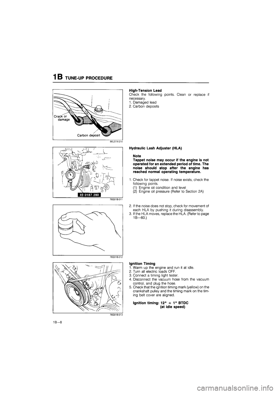
High-Tension Lead
Check the following points. Clean or replace if
necessary.
1. Damaged lead
2. Carbon deposits
86U01X-014
i^rrr ' /
49 0187 280
76G01B-011
76G01B-012
Hydraulic Lash Adjuster (HLA)
Note
Tappet noise may occur if the engine is not
operated for an extended period of time. The
noise should stop after the engine has
reached normal operating temperature.
1. Check for tappet noise. If noise exists, check the
following points.
(1) Engine oil condition and level
(2) Engine oil pressure (Refer to Section 2A)
2. If the noise does not stop, check for movement of
each HLA by pushing it during disassembly.
3. If the HLA moves, replace the HLA. (Refer to page
1B—60.)
Ignition Timing
1. Warm up the engine and run it at idle.
2. Turn all electric loads OFF.
3. Connect a timing light tester.
4. Disconnect the vacuum hose from the vacuum
control, and plug the hose.
5. Check that the ignition timing mark (yellow) on the
crankshaft pulley and the timing mark on the tim-
ing belt cover are aligned.
Ignition timing: 12° ± 1° BTDC
(at idle speed)
76G01B-008
1B—8
Page 142 of 1865

ON-VEHICLE MAINTENANCE (TIMING BELT) 1 B
ON-VEHICLE MAINTENANCE
TIMING BELT
Removal
1. Disconnect the negative battery cable.
2. Remove in the sequence shown in the figure referring to the removal note for specially marked parts.
76G01A-108
76G01B-020
1. Center cover
2. High-tension lead and spark plug
3. Engine side cover
4. Drive belt
5. Crankshaft pulley
6. Engine mount bracket
7. Upper timing belt cover
8. Lower timing belt cover
9. Baffle plate
10. Timing belt tensioner
11. Timing belt tensioner spring
12. Timing belt
1B—11
Page 143 of 1865

ON-VEHICLE MAINTENANCE (TIMING BELT) 1 B
76G01B-021
Removal note
Timing belt tensioner
1. Turn the crankshaft to align the mating marks of
the camshaft pulleys.
Note
For intake side camshaft pulley, align "I"
mark.
For exhaust side camshaft pulley, align "E"
mark.
2. Remove the tensioner.
Timing belt
Mark the timing belt rotation for proper reinstallation
if it is reused.
Caution
Be careful not to allow oil, grease, or water
on the belt.
86U01X-024
Inspection
Inspect the following parts. (Refer to page 1B—46,
47.)
1. Timing belt
2. Timing belt tensioner and spring
3. Timing belt idler pulley
4. Timing belt pulley
5. Camshaft pulley
76G01B-022
1B—12
Page 144 of 1865

1 B ON-VEHICLE MAINTENANCE (TIMING BELT)
Installation
Install in the reverse order of removal referring to the installation note.
Torque Specifications 76G01A-109
8—12 N m (80—120 cm-kg, 69—104 In-lb)
Installation note
Timing belt
1. Check that the mark on the timing belt pulley is
aligned with the mating mark.
2. Check that the mating mark of the camshaft pul-
leys are aligned with the seal plate mating marks.
Note
For intake side camshaft pulley, align "I"
mark.
For exhaust side camshaft pulley, align "E"
mark.
76G01B-026
1B—13
Page 145 of 1865

1 B ON-VEHICLE MAINTENANCE (TIMING BELT)
3. Install the timing belt tensioner and spring. Tem-
porarily secure it with the spring fully extended.
Caution
Do not damage the pulleys when securing the
tensioner pulley.
76G01B-024
4. Install the timing belt so that there is no looseness
at the tension side, and at the two camshaft pulleys.
Caution
a) If the timing belt is being reused, it must be
reinstalled to rotate in the original direction.
b) Check that there is no oil, grease, or dirt on
the timing belt.
76G01B-025
5. Loosen the tensioner lock bolt.
6. Turn the crankshaft twice in the direction of rota-
tion, and align the mating marks.
7. Check that the timing marks are correctly aligned.
If not aligned, remove the timing belt tensioner and
timing belt, and repeat steps 1—6.
69G01B-027
8. Turn the crankshaft to align the "S" mark of the
right side camshaft pulley with seal plate mating
mark.
Tighten the timing belt tensioner lock bolt.
Tightening torque:
37—52 Nm (3.8—5.3 m-kg, 27—38 ft-lb)
76G01B-026
1B—14
Page 146 of 1865

ON-VEHICLE MAINTENANCE (TIMING BELT) 1 B
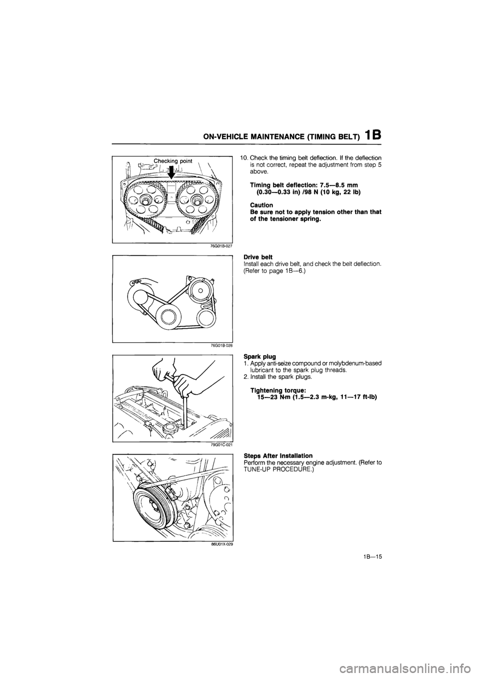
10. Check the timing belt deflection. If the deflection
is not correct, repeat the adjustment from step 5
above.
Timing belt deflection: 7.5—8.5 mm
(0.30—0.33 in) /98 N (10 kg, 22 lb)
Caution
Be sure not to apply tension other than that
of the tensioner spring.
76G01B-027
Drive belt
Install each drive belt, and check the belt deflection.
(Refer to page 1B—6.)
76G01B-028
Spark plug
1. Apply anti-seize compound or molybdenum-based
lubricant to the spark plug threads.
2. Install the spark plugs.
Tightening torque:
15—23
N
m (1.5—2.3 m-kg, 11—17 ft-lb)
79G01C-021
Steps After Installation
Perform the necessary engine adjustment. (Refer to
TUNE-UP PROCEDURE.)
86U01X-029
1B—15