timing belt MAZDA 626 1987 Service Manual
[x] Cancel search | Manufacturer: MAZDA, Model Year: 1987, Model line: 626, Model: MAZDA 626 1987Pages: 1865, PDF Size: 94.35 MB
Page 148 of 1865

1 B ON-VEHICLE MAINTENANCE (CYLINDER HEAD)
1. Center cover
2. High-tension lead and spark plug
3. Accelerator cable
4. Air intake pipe assembly
5. Fuel hose
6. Upper radiator hose
7. Heater hose
8. Brake vacuum hose
9. Canister hose (Unleaded fuel)
10. Engine harness connector and ground
11. EGR pipe (Unleaded fuel)
12. A/C compressor and bracket
13. Exhaust manifold insulator
14. Exhaust pipe
15. Exhaust manifold
16. Intake manifold bracket
17. Intake manifold assembly
18. Distributor
19. Engine mount stay
20. Upper timing belt cover
21. Timing belt tensioner spring
22. Timing belt
23. Cylinder head cover
24. Cylinder head and gasket
76G01B-030
Removal note
Fuel hose
Warning
a) Cover the hose with a rag because fuel will
spray out when disconnecting.
b) Keep sparks and open flame away from the
fuel area.
Plug the disconnected hoses to avoid fuel leakage.
86U01X-032
Timing belt
1. Before removing the timing belt, turn the crankshaft
to align the mating marks of the camshaft pulleys
with the seal plate timing mark.
Note
For intake side camshaft pulley, align "I"
mark.
For exhaust side camshaft pulley, align "E"
mark.
76G01B-031
2. Loosen the timing belt tensioner lock bolt.
3. Shift the tensioner outward as far as possible, then
temporarily tighten it.
76G01B-034
1B—17
Page 149 of 1865

1 B ON-VEHICLE MAINTENANCE (CYLINDER HEAD)
69G01B-037
CP ® (9) (I)
maj
q Jo o ph£j
@ ® (D
76G01A-111
4. Remove the timing belt and secure it out of the way
to prevent damage during removal and installation
of the cylinder head.
Cylinder head bolt
Loosen the cylinder head bolts in two or three steps
in the order shown in the figure.
Disassembly of Cylinder Head
Refer to page 1B—28.
Inspection of Cylinder Head
Refer to page 1B—34.
Assembly of Cylinder Head
Refer to page 1B—59.
76G01B-032
1B—18
Page 151 of 1865

1 B ON-VEHICLE MAINTENANCE (CYLINDER HEAD)
Installation note
Cylinder head
1. Thoroughly remove all dirt and oil from the top of
the cylinder block with a rag.
2. Place a new cylinder head gasket in position.
86U01X-035
® © © (D ® 3. Set the cylinder head in place.
4. Apply engine oil to the bolt threads and seat faces.
5. Tighten the cylinder head bolts in two or three steps
in the order shown in the figure.
Tightening torque:
80—86
N
m (8.2—8.8 m-kg, 59—64 ft-lb)
86U01X-036
Cylinder head cover
1. Apply silicon sealant to the shaded area as shown
in the figure.
2. Install the cylinder head cover and gasket.
Tightening torque:
4—6 N-m (40—60 cm-kg, 35—52 in-lb)
76G01B-033
Timing belt
1. Align the mating marks of the camshaft pulleys with
the seal plate timing mark.
Note
For intake side camshaft pulley, align "I"
mark.
For exhaust side camshaft pulley, align "E"
mark.
2. Install the timing belt. (Refer to TIMING BELT of
ON-VEHICLE MAINTENANCE.)
76G01B-034
1B—20
Page 157 of 1865

1 B DISASSEMBLY (TIMING BELT)
TIMING BELT
69G01B-072
1. Crankshaft pulley 6. Timing belt idler pulley
2. Upper timing belt cover 7. Timing belt
3. Lower timing belt cover 8. Camshaft pulley
4. Baffle plate 9. Timing belt pulley
5. Timing belt tensioner and spring
1B—26
Page 158 of 1865

DISASSEMBLY (TIMING BELT) 1 B
Mark the
direction of
rotation
76G01A-121
76G01B-119
Disassembly Note
Crankshaft pulley
1. Set the SST against the flywheel.
2. Remove the crankshaft pulley.
Timing belt
1. Loosen the tensioner lock bolt, and remove the ten-
sioner spring.
2. Mark the timing belt rotation for proper reinstalla-
tion if it is reused.
3. Remove the timing belt.
Caution
Be careful not to allow oil or grease on the
belt.
Camshaft pulley
Remove the pulley lock bolt using a screw driver to
prevent the camshaft from turning.
76G01A-123
1B—27
Page 177 of 1865

INSPECTION AND REPAIR 1 B
Rolled fillet
Crankpin journal diameter undersize mm (in)
Bearing size Journal diameter
0.25 (0.010) undersize 50.690-50.705 (1.9957—1.9963)
0.50 (0.020) undersize 50.440—50.455 (1.9858-1.9864)
0.75 (0.030) undersize 50.190-50.205 (1.9760-1.9766)
Caution
Do not grind the rolled fillet area.
76G01A-133
Main Bearing and Connecting Rod Bearing
Check the main bearings and the connecting rod
bearings for peeling, scoring, or other damage.
79G01C-077
Oil Jet
1. Check that the oil passage is not clogged.
2. Check that the check ball is not stuck.
76G01B-069
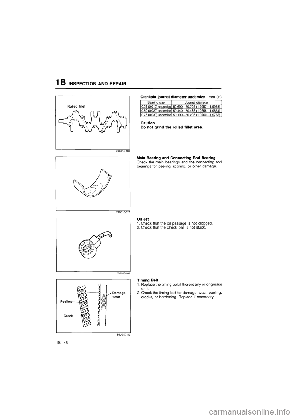
Timing Belt
1. Replace the timing belt if there is any oil or grease
on it.
2. Check the timing belt for damage, wear, peeling,
cracks, or hardening. Replace if necessary.
86U01X-101
1B—46
Page 178 of 1865

INSPECTION AND REPAIR 1 B
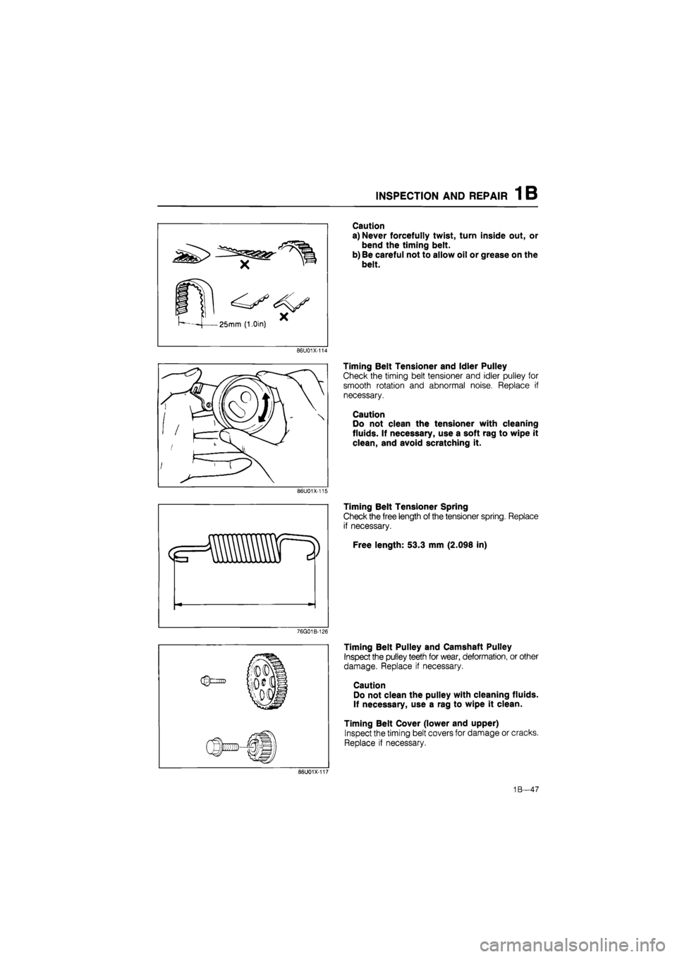
Caution
a) Never forcefully twist, turn inside out, or
bend the timing belt.
b) Be careful not to allow oil or grease on the
belt.
86U01X-114
Timing Belt Tensioner and Idler Pulley
Check the timing belt tensioner and idler pulley for
smooth rotation and abnormal noise. Replace if
necessary.
Caution
Do not clean the tensioner with cleaning
fluids. If necessary, use a soft rag to wipe it
clean, and avoid scratching it.
86U01X-115
Timing Belt Tensioner Spring
Check the free length of the tensioner spring. Replace
if necessary.
Free length: 53.3 mm (2.098 in)
76G01B-126
Timing Belt Pulley and Camshaft Pulley
Inspect the pulley teeth for wear, deformation, or other
damage. Replace if necessary.
Caution
Do not clean the pulley with cleaning fluids.
If necessary, use a rag to wipe it clean.
Timing Belt Cover (lower and upper)
Inspect the timing belt covers for damage or cracks.
Replace if necessary.
86U01X-101
1B—47
Page 195 of 1865

1 B ASSEMBLY (TIMING BELT)
TIMING BELT
Torque Specifications
47-65 N m (4.8—6,6 m-kg, 35—49
7—10 N-m (70—100 cm-kg, 61—87 in-ll'
12—17 Nm (1.25—1.75 m-kg, 109—152 in-lbj
167—167 N*m (16.0-17.0 m-kg, 116—123 tt-tti)
1B—64
69G01B-160
Page 196 of 1865

ASSEMBLY (TIMING BELT) 1 B
Camshaft Pulley
1. Install the camshaft pulley on the camshaft with the
dowel pin fit into the hole at the I mark (intake side)
and E mark (exhanst side).
76G01B-127
2. Tighten the camshaft pulley lock bolt.
Tightening torque:
47—65 Nm (4.8—6.6 m-kg, 35—48 ft-lb)
76G01A-141
3. Align the mating mark on the camshaft pulleys with
the alignment mark on the seal plate.
Note
For intake side camshaft pulley, align "I"
mark.
For exhanst side camshaft pulley, align "E"
mark.
76G01B-094
Timing Belt Pulley
1. Reverse the direction of the SST (ring gear brake).
2. Install the crankshaft key.
3. Install the timing belt pulley on the crankshaft.
Tightening torque: 157—167 N m
(16.0—17.0 m-kg, 116—123 ft-lb)
4. Release the ring gear brake.
5. Align the timing belt pulley and the pump body
alignment marks.
86U01X-160
1B—65
Page 197 of 1865

1 B ASSEMBLY (TIMING BELT)
69G01B-165
76G01B-095
79G01C-097
Timing Belt Idler Pulley
Install the timing belt idler pulley.
Tightening torque:
37—52 Nm (3.8—5.3 m-kg, 27—38 ft-lb)
Timing Belt Tensioner
1. Install the timing belt tensioner and tensioner
spring.
2. Tentatively secure the tensioner with the spring fully
extended.
Timing Belt
1. Install the timing belt so that there is no looseness
at the tension side, and at the two camshaft pulleys.
Caution
a) If the timing belt is being reused, it must be
reinstalled to rotate in the original direction.
b) Check that there is no oil, grease, or dirt on
the timing belt.
2. Loosen the tensioner lock bolt.
3. Turn the crankshaft twice in the direction of rotation.
4. Check that the mating marks are correctly aligned.
If not aligned, remove the timing belt and tension-
er, and repeat the above-mentioned procedure.
5. Turn the crankshaft to align the S mark of the right
side camshaft pulley with seal plate mating mark.
6. Tighten the timing belt tensioner lock bolt.
Tightening torque:
37—52
N
m (3.8—5.3 m-kg, 27—38 ft-lb)
76G01B-096
1B-66