engine MAZDA 626 1987 Workshop Manual
[x] Cancel search | Manufacturer: MAZDA, Model Year: 1987, Model line: 626, Model: MAZDA 626 1987Pages: 1865, PDF Size: 94.35 MB
Page 779 of 1865
STATRER (DIESEL ENGINE, 2.2 KW TYPE) 5
11*mm S (0.433 in)
A
A 18 mm
(0,709)
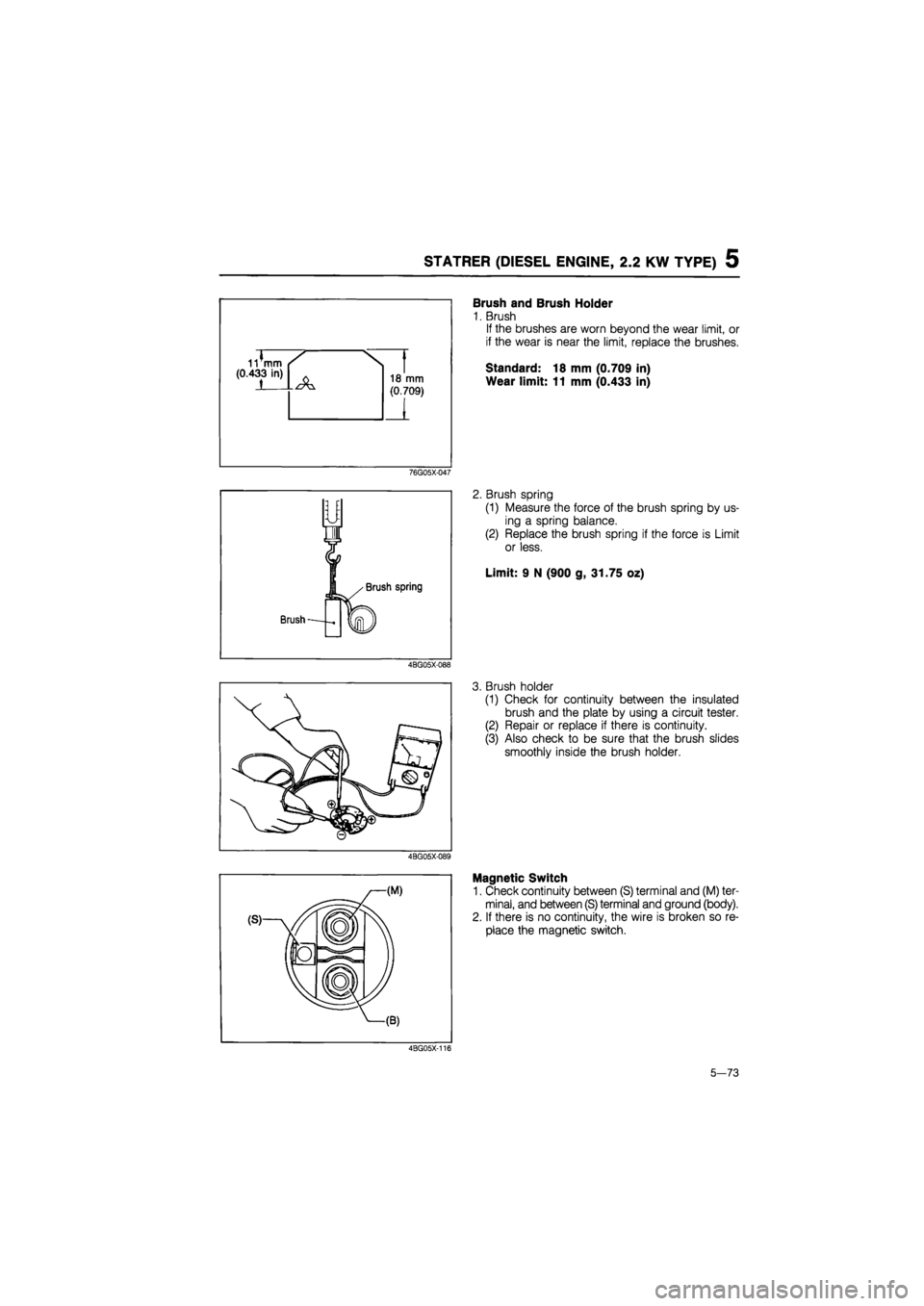
Brush and Brush Holder
1. Brush
If the brushes are worn beyond the wear limit, or
if the wear is near the limit, replace the brushes.
Standard: 18 mm (0.709 in)
Wear limit: 11 mm (0.433 in)
76G05X-047
2. Brush spring
(1) Measure the force of the brush spring by us-
ing a spring balance.
(2) Replace the brush spring if the force is Limit
or less.
Limit: 9 N (900 g, 31.75 oz)
4BG05X-088
3. Brush holder
(1) Check for continuity between the insulated
brush and the plate by using a circuit tester.
(2) Repair or replace if there is continuity.
(3) Also check to be sure that the brush slides
smoothly inside the brush holder.
4BG05X-089
Magnetic Switch
1. Check continuity between (S) terminal and (M) ter-
minal, and between (S) terminal and ground (body).
2. If there is no continuity, the wire is broken so re-
place the magnetic switch.
4BG05X-116
5-73
Page 780 of 1865
5 STARTER (DIESEL ENGINE, 2.2 KW TYPE)
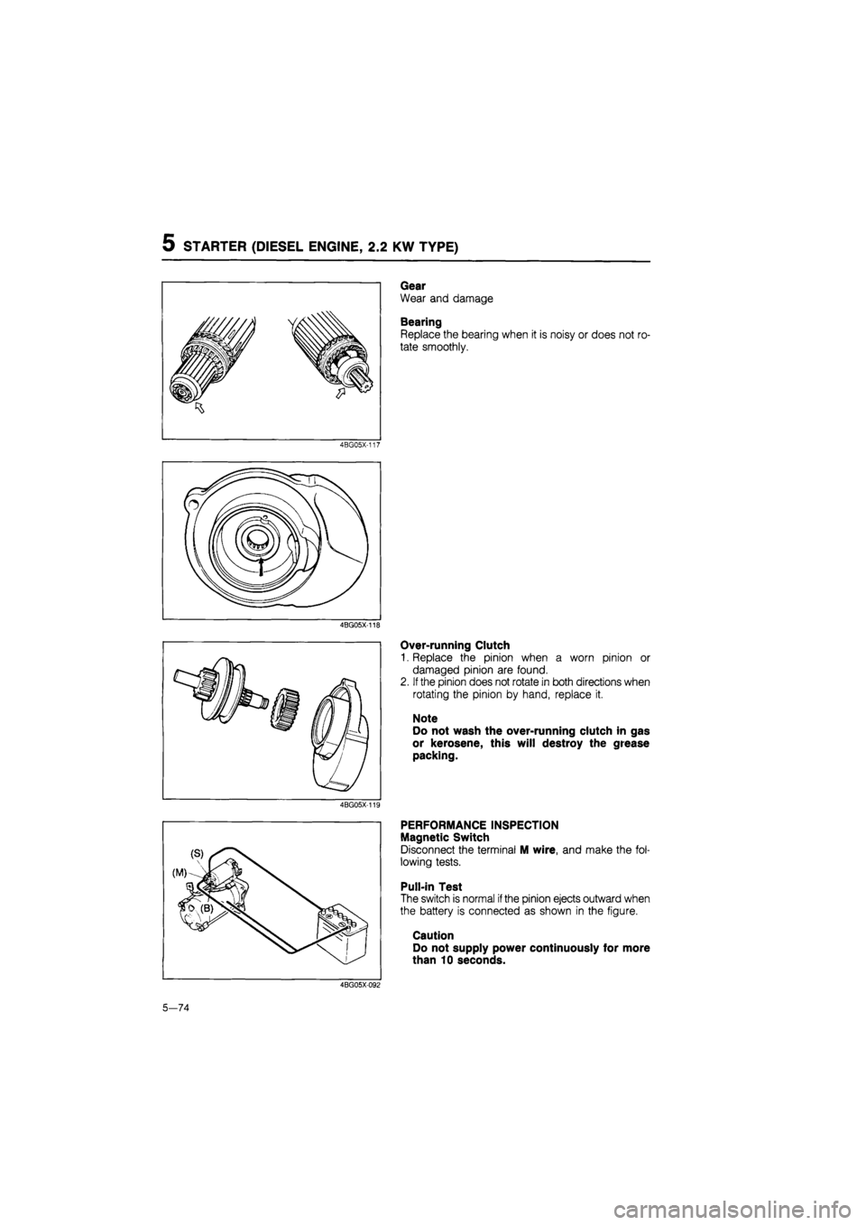
Gear
Wear and damage
Bearing
Replace the bearing when it is noisy or does not ro-
tate smoothly.
4BG05X-117
4BG05X-118
Over-running Clutch
1. Replace the pinion when a worn pinion or
damaged pinion are found.
2.
If
the pinion does not rotate in both directions when
rotating the pinion by hand, replace it.
Note
Do not wash the over-running clutch in gas
or kerosene, this will destroy the grease
packing.
4BG05X-119
PERFORMANCE INSPECTION
Magnetic Switch
Disconnect the terminal M wire, and make the fol-
lowing tests.
Pull-in Test
The switch is normal
if
the pinion ejects outward when
the battery is connected as shown in the figure.
Caution
Do not supply power continuously for more
than 10 seconds.
4BG05X-092
5—74
Page 781 of 1865
5 STARTER (DIESEL ENGINE, 2.0 KW TYPE)
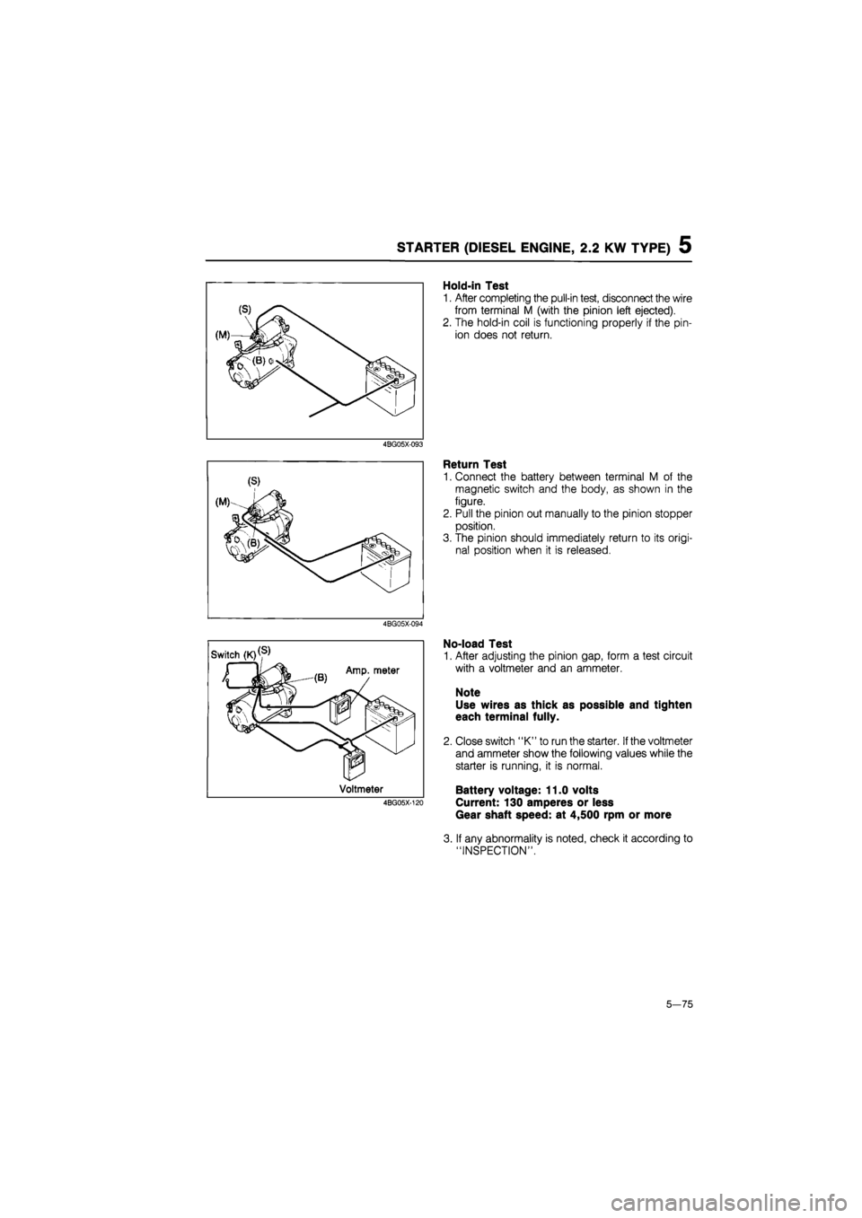
Hold-in Test
1. After completing the pull-in test, disconnect the wire
from terminal M (with the pinion left ejected).
2. The hold-in coil is functioning properly if the pin-
ion does not return.
4BG05X-093
Return Test
1. Connect the battery between terminal M of the
magnetic switch and the body, as shown in the
figure.
2. Pull the pinion out manually to the pinion stopper
position.
3. The pinion should immediately return to its origi-
nal position when it is released.
4BG05X-094
No-load Test
1. After adjusting the pinion gap, form a test circuit
with a voltmeter and an ammeter.
Note
Use wires as thick as possible and tighten
each terminal fully.
2. Close switch "K" to run the starter.
If
the voltmeter
and ammeter show the following values while the
starter is running, it is normal.
Battery voltage: 11.0 volts
Current: 130 amperes or less
Gear shaft speed: at 4,500 rpm or more
3. If any abnormality is noted, check it according to
"INSPECTION".
5—75
Page 783 of 1865
QUICK START SYSTEM (QSS) 5
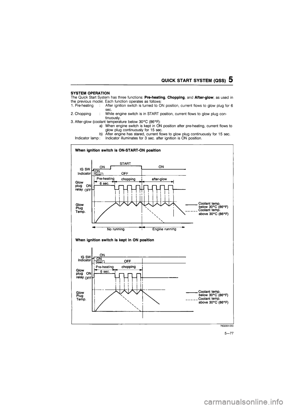
SYSTEM OPERATION
The Quick Start System has three functions: Pre-heating, Chopping, and After-glow; as used in
the previous model. Each function operates as follows:
1. Pre-heating After ignition switch is turned to ON position, current flows to glow plug for 6
sec.
2. Chopping While engine switch is in START position, current flows to glow plug con-
tinuously.
3. After-glow (coolant temperature below 30°C (86°F):
a) When engine switch is kept in ON position after pre-heating, current flows to
glow plug continuously for 15 sec.
b) After engine has stared, current flows to glow plug continuously for 15 sec.
Indicator lamp: Indicator illuminates for 3 sec. after ignition is ON position.
When ignition switch is ON-START-ON position
When ignition switch is kept in ON position
76G05X-050
5-77
Page 784 of 1865
QUICK START SYSTEM (QSS) 5
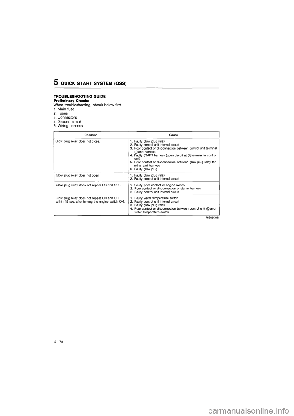
TROUBLESHOOTING GUIDE
Preliminary Checks
When troubleshooting, check below first.
1. Main fuse
2. Fuses
3. Connectors
4. Ground circuit
5. Wiring harness
Condition Cause
Glow plug relay does not close. 1. Faulty glow plug relay 2. Faulty control unit internal circuit
3. Poor contact or disconnection between control unit terminal ©and harness
4. Faulty START harness (open circuit at ©terminal in control unit) 5. Poor contact or disconnection between glow plug relay ter-minal and harness 6. Faulty glow plug
Glow plug relay does not open 1. Faulty glow plug relay 2. Faulty control unit internal circuit
Glow plug relay does not repeat ON and OFF. 1. Faulty poor contact of engine switch 2. Poor contact or disconnection of starter harness 3. Faulty control unit internal circuit
Glow plug relay does not repeat ON and OFF within 15 sec. after turning the engine switch ON. 1. Faulty water temperature switch 2. Faulty control unit internal circuit
3. Faulty glow plug relay
4. Poor contact or disconnection between control unit © and water temperature switch
76G05X-051
5-78
Page 785 of 1865
QUICK START SYSTEM (QSS) 5
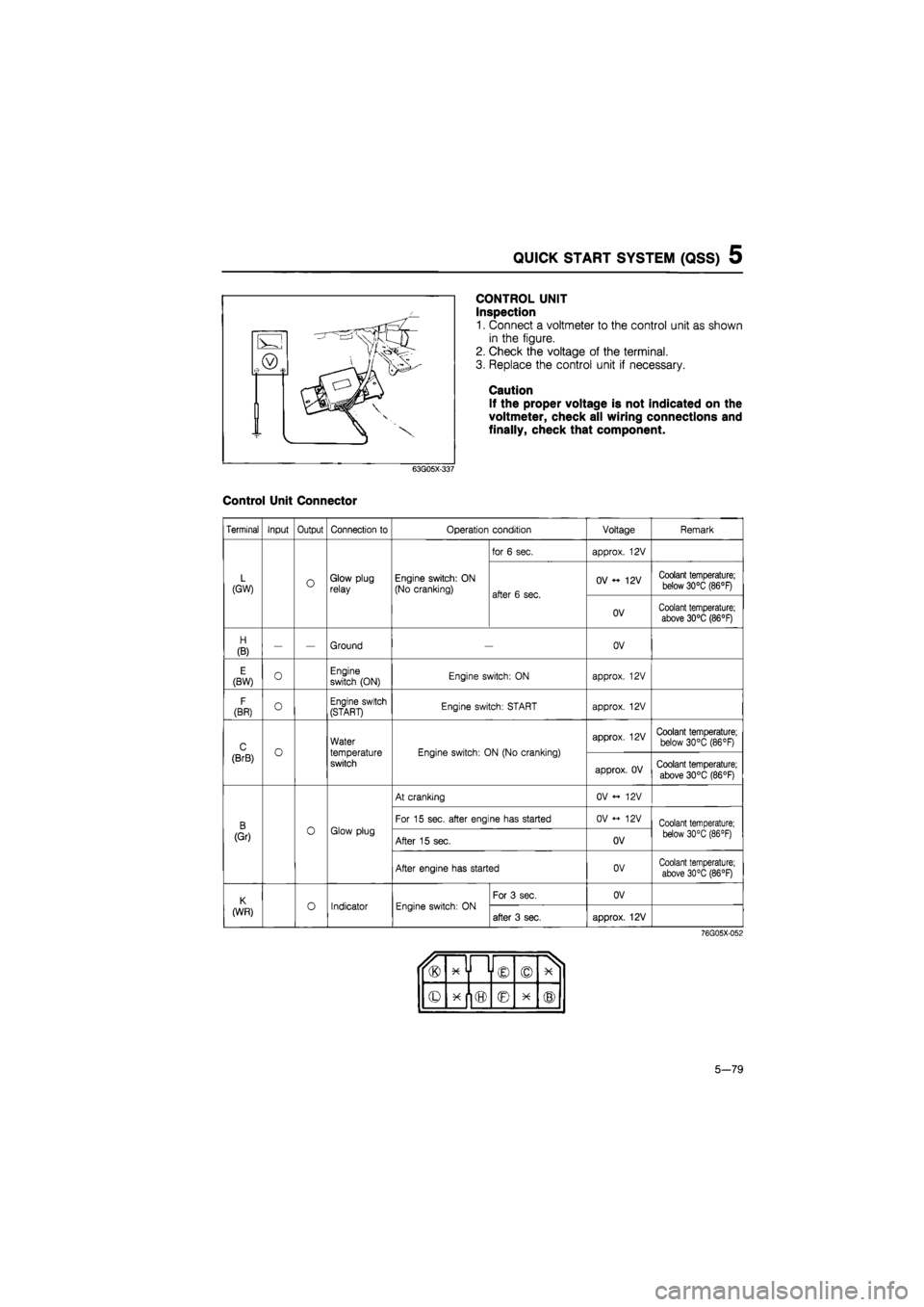
CONTROL UNIT
Inspection
1. Connect a voltmeter to the control unit as shown
in the figure.
2. Check the voltage of the terminal.
3. Replace the control unit if necessary.
Caution
If the proper voltage is not indicated on the
voltmeter, check all wiring connections and
finally, check that component.
63G05X-337
Control Unit Connector
Terminal Input Output Connection to Operation condition Voltage Remark
for 6 sec. approx. 12V
L (GW) O Glow plug relay Engine switch: ON (No cranking) after 6 sec.
OV 12V Coolant temperature; below 30°C (86°F) after 6 sec.
OV Coolant temperature; above 30°C (86°F)
H
(B) — — Ground OV
E (BW) 0 Engine switch (ON) Engine switch: ON approx. 12V
F
(BR) O Engine switch (START) Engine switch: START approx. 12V
C o
Water
temperature switch
Engine switch: ON (No cranking)
approx. 12V Coolant temperature; below 30°C (86°F)
(BrB) o
Water
temperature switch
Engine switch: ON (No cranking)
approx. OV Coolant temperature;
above 30°C (86°F)
At cranking OV <- 12V
B 0 Glow plug
For 15 sec. after engine has started OV <-> 12V Coolant temperature;
(Gr) 0 Glow plug After 15 sec. OV below 30°C (86 °F)
After engine has started OV Coolant temperature; above 30°C (86°F)
K o Indicator Engine switch: ON
For 3 sec. OV
(WR) o Indicator Engine switch: ON after 3 sec. approx. 12V
76G05X-052
u® x y i © © X 1
© © X ®
5-79
Page 789 of 1865
TROUBLESHOOTING GUIDE 6
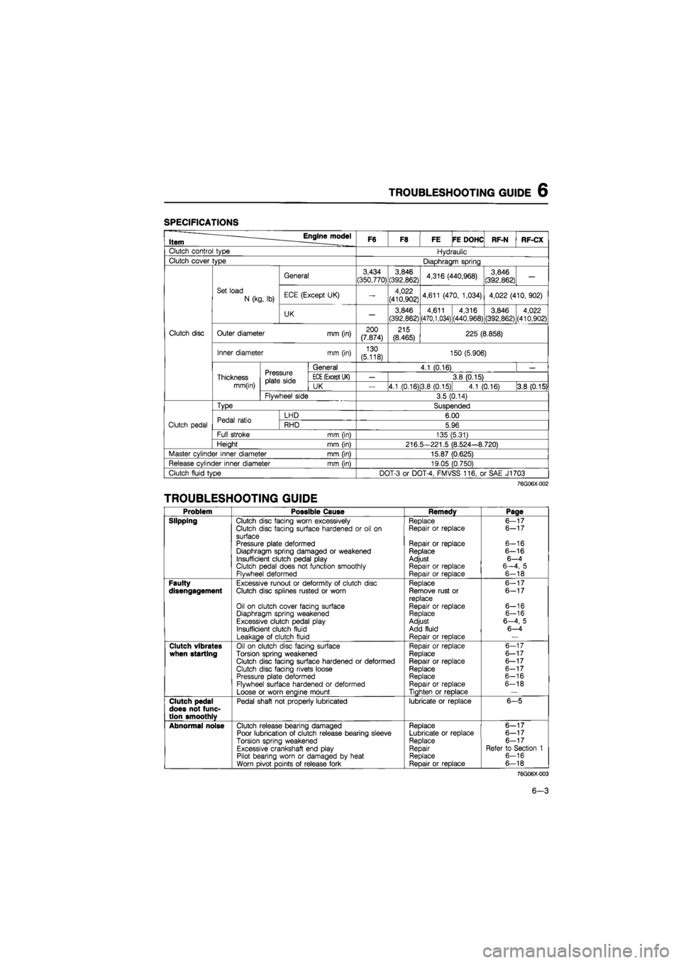
SPECIFICATIONS
Item Engine model F6 F8 FE FE DOHC RF-N RF-CX
Clutch control type Hydraulic
Clutch cover type Diaphragm spring
General 3,434
(350,770) 3,846
(392,862) 4,316 (440,968) 3,846
(392,862) —
Set load
N (kg, lb) ECE (Except UK) — 4,022
(410,902) 4,611 (470, 1,034) 4,022 (410, 902)
UK — 3,846
(392,862)
4,611 (470,1,034) 4,316
(440,968)
3,846 (392,862) 4,022 (410,902)
Clutch disc Outer diameter mm (in) 200 (7.874) 215 (8.465) 225 (8.858)
Inner diameter mm (in) 130 (5.118) 150 (5.906)
Pressure plate side
General 4.1 (0.16) —
Thickness Pressure plate side
ECE
(Except UK) — 3.8 (0.15)
mm(in)
Pressure plate side UK 4.1 (0.16)13.8 (0.15) 4.1 (0.16) 3.8 (0.15)
Flywheel side 3.5 (0.14)
Type Suspended
Pedal ratio LHD 6.00
Clutch pedal Pedal ratio RHD 5.96
Full stroke mm (in) 135 (5.31)
Height mm (in) 216.5-221.5 (8.524-8.720)
Master cylinder inner diameter mm (in) 15.87 (0.625)
Release cylinder inner diameter mm (in) 19.05 (0.750)
Clutch fluid type DOT-3 or DOT-4, FMVSS 116, or SAE J1703
76G06X-002
TROUBLESHOOTING GUIDE
Problem Possible Cause Remedy Page
Slipping Clutch disc facing worn excessively Replace 6—17 Clutch disc facing surface hardened or oil on Repair or replace 6-17
surface Pressure plate deformed Repair or replace 6-16 Diaphragm spring damaged or weakened Replace 6-16 Insufficient clutch pedal play Adjust 6—4 Clutch pedal does not function smoothly Repair or replace 6—4, 5 Flywheel deformed Repair or replace 6-18
Faulty Excessive runout or deformity of clutch disc Replace 6-17 disengagement Clutch disc splines rusted or worn Remove rust or 6—17 replace Oil on clutch cover facing surface Repair or replace 6-16 Diaphragm spring weakened Replace 6-16
Excessive clutch pedal play Adjust 6—4, 5
Insufficient clutch fluid Add fluid 6-4
Leakage of clutch fluid Reoair or reDlace —
Clutch vibrates Oil on clutch disc facing surface Repair or replace 6-17 when starting Torsion spring weakened Replace 6-17 Clutch disc facing surface hardened or deformed Repair or replace 6-17
Clutch disc facing rivets loose Replace 6-17 Pressure plate deformed Replace 6-16
Flywheel surface hardened or deformed Repair or replace 6-18
Loose or worn engine mount Tighten or replace —
Clutch pedal Pedal shaft not properly lubricated lubricate or replace 6-5 does not func-tion smoothlv
Abnormal noise Clutch release bearing damaged Replace 6—17 Poor lubrication of clutch release bearing sleeve Lubricate or replace 6-17
Torsion spring weakened Replace 6-17
Excessive crankshaft end play Repair Refer to Section 1 Pilot bearing worn or damaged by heat Replace 6-16
Worn pivot points of release fork • Reoair or replace 6-18
76G06X-003
6-3
Page 801 of 1865
CLUTCH AND FLYWHEEL 6
CLUTCH AND FLYWHEEL
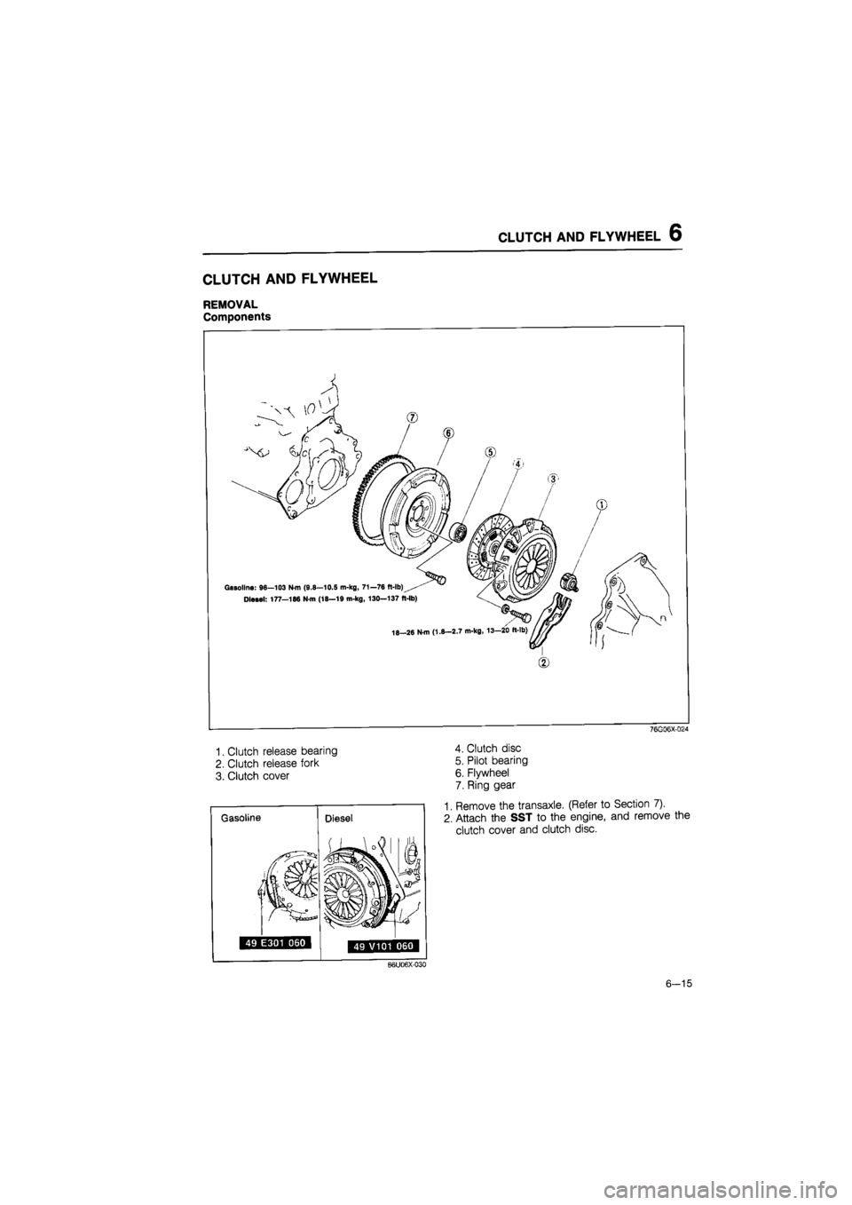
REMOVAL
Components
Gasoline: 96—103 N-m (9.8—10.5 m-kg, 71—76 ft-lb)
Diesel: 177—186 N-m (18—19 m-kg, 130—137 ft-lb)
18-26 N-m (1.8—2.7 m-kg, 13—20 ft-lb)
1. Clutch release bearing
2. Clutch release fork
3. Clutch cover
76G06X-024
4. Clutch disc
5. Pilot bearing
6. Flywheel
7. Ring gear
1. Remove the transaxle. (Refer to Section 7).
2. Attach the SST to the engine, and remove the
clutch cover and clutch disc.
B6U06X-030
6-15
Page 804 of 1865
6 CLUTCH AND FLYWHEEL
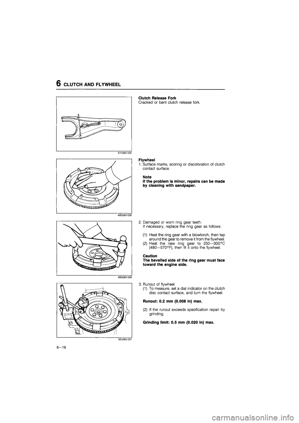
Clutch Release Fork
Cracked or bent clutch release fork.
67U06X-035
4BG06X-028
4BG06X-029
Flywheel
1. Surface marks, scoring or discoloration of clutch
contact surface.
Note
If the problem is minor, repairs can be made
by cleaning with sandpaper.
2. Damaged or worn ring gear teeth.
If necessary, replace the ring gear as follows:
(1) Heat the ring gear with a blowtorch, then tap
around the gear to remove
it
from the flywheel.
(2) Heat the new ring gear to 250—300°C
(480—570°F), then fit it onto the flywheel.
Caution
The bevelled side of the ring gear must face
toward the engine side.
3. Runout of flywheel
(1) To measure, set a dial indicator on the clutch
disc contact surface, and turn the flywheel.
Runout: 0.2 mm (0.008 in) max.
(2) If the runout exceeds specification repair by
grinding.
Grinding limit: 0.5 mm (0.020 in) max.
86U06X-037
6-18
Page 810 of 1865
7A OUTLINE
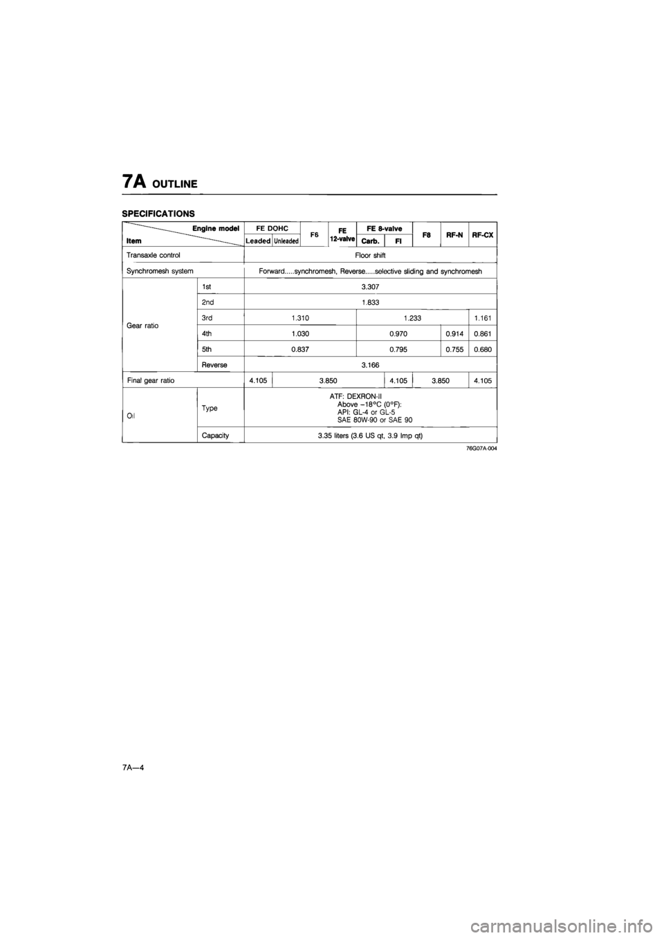
SPECIFICATIONS
•Engine model
Item ——
FE DOHC F6 FE 12-valve
FE 8-valve F8 RF-N RF-CX •Engine model
Item —— Leaded Unleaded F6 FE 12-valve Carb. Fl F8 RF-N RF-CX
Transaxle control Floor shift
Synchromesh system Forward synchromesh, Reverse selective sliding and synchromesh
Gear ratio
1st 3.307
Gear ratio
2nd 1.833
Gear ratio 3rd 1.310 1.233 1.161 Gear ratio
4th 1.030 0.970 0.914 0.861
Gear ratio
5th 0.837 0.795 0.755 0.680
Gear ratio
Reverse 3.166
Final gear ratio 4.105 3.850 4.105 3.850 4.105
Oil Type
ATF: DEXRON-II Above -18°C (0°F): API: GL-4 or GL-5 SAE 80W-90 or SAE 90 Oil
Capacity 3.35 liters (3.6 US qt, 3.9 Imp qt)
76G07A-004
7A—4