engine MAZDA 626 1987 Workshop Manual
[x] Cancel search | Manufacturer: MAZDA, Model Year: 1987, Model line: 626, Model: MAZDA 626 1987Pages: 1865, PDF Size: 94.35 MB
Page 872 of 1865

7B OUTLINE
OPERATION OF COMPONENTS
Low and reverse brake
76U07B-508
Operation Table (G4A-EL)
Range Gear Engine
braking
effect
Operation elements
Range Gear Engine
braking
effect Forward
clutch
Coasting
clutch 3-4
clutch Reverse
clutch
2-4 brake Loftrmm
brake
One-way
clutch 1
One-way clutch 2
Range Gear Engine
braking
effect Forward
clutch
Coasting
clutch 3-4
clutch Reverse
clutch Aoolied Released
Loftrmm
brake
One-way
clutch 1
One-way clutch 2
P — —
R Reverse Yes O O
N -—
D
1st No O O O
D
2nd No o O 0
D 3rd
Below approx.
40 km/h (25 mph)
Yes o O 0 O 0 D 3rd
Above
approx.
40 km/h (25 mph)
Yes 0 o o ® o o
D
OD Yes © o o
S
1st No o 0 o
S
2nd No o 0 0
S
3rd
Below
approx,
40 km/h (25 mph)
Yes 0 0 0 0 o S
3rd Above approx.
40 km/h (25 mph)
Yes o o o ® o o
L 1st No o O o o L 2nd Yes 0 0 o o
HOLD
D
2nd No o o o
HOLD
D 3rd
Below
approx.
40 km/h (25
mpti) Yes o o o 0 o
HOLD
D 3rd Above approx,
40 km/h (25 mph)
Yes o 0 o ® 0 o
HOLD
S
2nd Yes o o 0 o
HOLD
S 3rd
Below approx.
40 km/h (25 mph)
Yes 0 o o 0 o
HOLD
S 3rd Above approx.
40 km/h (25 mph)
Yes o o o ® 0 o
HOLD
L 1st Yes o o o o o
HOLD
L 2nd Yes o 0 0 o
®: Indicates fluid pressure to servo but band not applied due to pressure difference in servo. 76G07B-006 © : Indicates that it does not function to transmition power.
7B-6
Page 873 of 1865

OUTLINE 7B
Operation Table (G4A-HL)
Range Gear
Operation elements
Range Gear Engine braking effect
Forward
clutch
Coasting
clutch
3-4 clutch Reverse clutch
2-4 brake Low & One-way
clutch 1
One-way
clutch 2
Range Gear Engine braking effect
Forward
clutch
Coasting
clutch
3-4 clutch Reverse clutch Applied Released reverse brake
One-way
clutch 1
One-way
clutch 2
P
— —
R
—
Yes O 0
N
— —
D
1st No O O O
D 2nd No
o
O
o
D 3rd Yes
o
O 0
®
0
o
D
OD Yes
© O 0
2 2nd Yes
o o o o
1 1st Yes
o o o o o
1 2nd Yes
o o o o
76G07B-007
® : Indicates fluid pressure to servo but band not applied due to pressure difference in servo.
® : Indicates that it does not function to transmit power.
POWER FLOW DIAGRAM
Neutral
1st gear
7B-7
Page 878 of 1865

7B TROUBLESHOOTING (G4A-EL)
TROUBLESHOOTING (G4A-EL)
GENERAL NOTE
In the event of a problem with the EC-AT, the cause may be in the engine, EC-AT power train, hydrau-
lic control system, or electronic control system.
When troubleshooting, therefore, it is recommended to begin from those points that can be judged
quickly and easily. The recommended troubleshooting sequence is described below.
76G07B-012
7B-12
Page 880 of 1865

7B TROUBLESHOOTING (G4A-EL)
ON VEHICLE-
-f-
—OFF VEHICLE
\ Inspection point
and
\ reference page
Condition
•
Electronic control system Prelim-
inary
Hydraulic
control
system
Power train \ Inspection point
and
\ reference page
Condition
•
7B-66
m CO I m r--
7B-63
i
cn to I m
Section
4B
|
Section
4B
|
ID to i m
CO CO 1 CD
7B-68
|
en CO 1 IX)
to 1 00 r-.
cn CD 1 CO
7B-69
|
1 CD r--
cn s-1 m
Section
4B
r*-cn
S-1 CD h-
"=1-
rJ CO
7 CD r-
(XI o
1 m
cn CM 1 CD
7B-107
|
CD
7 CD 7 m
I
7B-113
I
CO CM
7 CO r-.
m cn
7 CO r-.
cn
7 DO r-
CM CM
7 CO
|
7B-126
CO
1*-r*-
7 m r-
\ Inspection point
and
\ reference page
Condition
•
Brake
light
switch
|
Inhibitor
switch
|
Mode
switch
|
1
CO. •o o X
Idle
switch
Throttle
sensor
|
Water
temp,
switch
|
0 tn c 0) cn
s
ffi
Q tn 01 o Hi >
Pulse
generator
|
"a o c 0) a to CM
TJ O CL ID s CO C\l 3-4
solenoid
|
Lock-up
solenoid
I
ATF
level
and
condition
|
Selector
lever
m Xj CO CJ 03
1 sz
Idle
speed
and
Ignition
timing
Control
valves
Accumulators
Oil
pump
Hydraulic
circuit
Torque
converter
Forward
clutch
Coasting
clutch
Reverse
clutch
JT O
u TT ro 2-4
brake
band
and
servo
$ 2
B cn cii > £ "O C CO
o
XI y
o >. CO S cb a O
One-way
clutch
2
s CI Cn tz JC 5 0-
Planetary
gear
Differential
assembly
Accelerating
Vehicle does
not
move
in
D,
S,
L,
or R
range
O O O O O O O O O O 0
Accelerating
Vehicle moves
in N
range -0 0 -—
Accelerating
Excessive creep
-0 O O -—
Accelerating
No creep
at all
O o o o
o
G 0 O O
Shifting
|
No shift
O O o
o
0 O 0 0
o
o O
Shifting
|
Abnormal shift sequence
0 o O O 0
o
o 0 O o o 0 O
Shifting
|
Frequent shifting 0 o 0 0 o 0 O O 0
Shifting
|
Excessively high
or
low
shift point 0 o 0 O 0 0 o 0 O 0 0
Shifting
|
No lock-up
0 o 0 0 o 0 O O o O
Shifting
|
No kick-down o o o o
Slipping
Engine
run
away
or
slip when
starting vehicle 0 o 0 O o O
Slipping
Engine
run
away
or
slip when
up-
or
down-shifting o o o 0 o O 0 0 O
8 n cn 4S SI V)
Excessive
N to D or N to R
shift shock o O o o o O
8 n cn 4S SI V)
Excessive shift shock when
up-
shifting
or
downshifting o o o o 0 0 0 8 n cn 4S SI V) Excessive shift shock when
changing range 0 0 o 0 o
j
Noise
Transaxle noisy
in N or P
range o o 0 O
j
Noise
Transaxle noisy
in D, S, L,
or
R range o 0 0 O
I
Others
j
No engine braking o O o 0 o o
I
Others
j
No mode change o 0 o o o o o o o
O
o
0
I
Others
j
Transaxle overheats
o o
0 o 0 o 0
I
Others
j
Vehicle moves
in
"P",
or
park-ing gear
not
disengaged when
"P"
is
dis-
engaged
0 O
I
Others
j
Hold indicator flashes o
0
o
0
o
O
o — — —
I
Others
j
Engine will
not
start
o
o
O — — —
76G07B-014
7B—14
Page 892 of 1865

7B TROUBLESHOOTING (G4A-EL)
Item Indication Condition
OUTPUT (Digital display)
1
1
st gear position
GEAR* 2 2nd gear position GEAR*
3 3rd gear position
4 Overdrive (OD) gear position
86U07B-033
Note
a) The back-up condition is as following condition
S range, hold mode, and the accelerator pedal depressed fully.
b)The * marked items should be checked during the engine running or driving.
Comprehensive Usage
The EC-AT Tester can be used to inspect slippage of friction elements, shift points, and shift sequence
during the road test.
The inspection procedure is shown in STEP 7 (ROAD TEST).
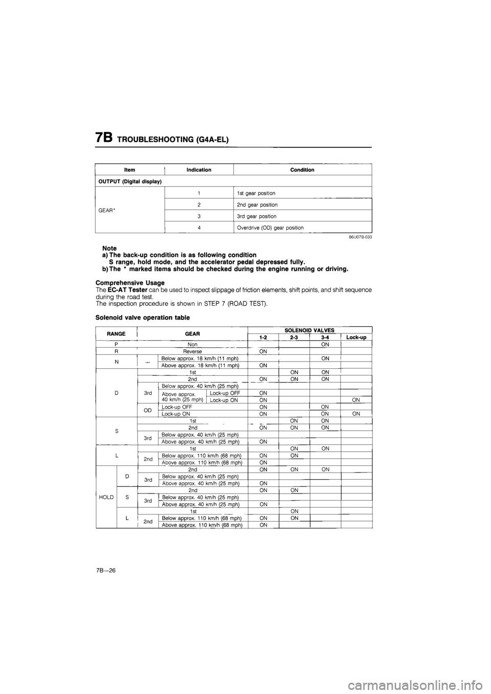
Solenoid valve operation table
RANGE GEAR SOLENOID VALVES RANGE GEAR 1-2 2-3 3-4 Lock-up
P Non ON
R Reverse ON
N Below aDDrox. 18 km/h (11 mDh) ON N Above approx. 18 km/h (11 mph) ON
1st ON ON
2nd ON ON ON
Below approx. 40 km/h (25 mph)
D 3rd Above approx. 40 km/h (25 mph)
Lock-uo OFF ON Above approx. 40 km/h (25 mph) Lock-up ON ON ON
OD Lock-up OFF ON ON OD Lock-uo ON ON ON ON
1st ON ON
S 2nd ON ON ON S
3rd Below approx. 40 km/h (25 mph) 3rd Above approx. 40 km/h (25 mph) ON
1st ON ON
L 2nd Below approx. 110 km/h (68 mph) ON ON 2nd Above approx. 110 km/h (68 moh) ON
2nd ON ON ON
D 3rd Below approx. 40 km/h (25 moh) 3rd Above approx. 40 km/h (25 moh) ON
2nd ON ON
HOLD S 3rd Below approx. 40 km/h (25 mph) 3rd Above approx. 40 km/h (25 mph) ON
1st ON
L 2nd Below approx. 110 km/h (68 mph) ON ON 2nd Above approx. 110 km/h (68 mph) ON
7B—26
Page 893 of 1865

TROUBLESHOOTING (G4A-EL) 7B
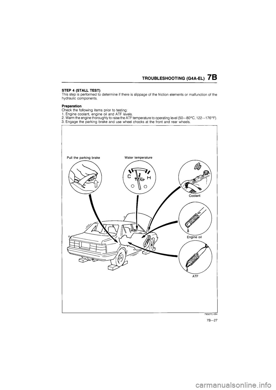
STEP 4 (STALL TEST)
This step is performed to determine if there is slippage of the friction elements or malfunction of the
hydraulic components.
Preparation
Check the following items prior to testing:
1. Engine coolant, engine oil and ATF levels.
2. Warm the engine thoroughly to raise the ATF temperature to operating level (50—80°C, 122—176°F).
3. Engage the parking brake and use wheel chocks at the front and rear wheels.
Pull the parking brake Water temperature
ATF
79G07C-084
7B-27
Page 894 of 1865

7B TROUBLESHOOTING (G4A-EL)
Procedure
86U07B-034
1. Block the wheels and apply the parking brake.
2. Connect a tachometer to the engine.
3. Shift the selector lever to R.
4. Firmly depress the foot brake with the left foot, and gently depress the accelerator pedal with the right.
5. When the engine speed no longer increases, quickly read the engine speed and release the ac-
celerator.
Caution
Steps 4 ->• 5 must be done within 5 seconds.
6. Move the selector lever to N and let the engine idle for at least one minute.
Caution
The reason for idling for at least one minute is to cool the ATF and to prevent deterioration
of the fluid.
7B-28
Page 895 of 1865

TROUBLESHOOTING (G4A-EL) 7B
7. Perform the stall test for the following ranges in the same manner.
(1) D range (4) L range
(2) D range (Hold) (5) L range (Hold)
(3) S range (Hold)
Caution
Be sure to allow sufficient cooling time between each stall test.
Engine stall speed: D.S.L range 2170—2270 rpm
R range 2130—2230 rpm
Note
The stall test can be performed with the EC-AT Tester in place of a tachometer.
Drum stall speed indication: 0 rpm
76G0/B-029
Evaluation
Condition Possible cause
Above specification
In all ranges Insufficient line
pressure
Worn oil pump
Above specification
In all ranges Insufficient line
pressure Oil leakage from oil pump, control valve, and/or transmission case
Stuck pressure regulator valve
Above specification
In forward ranges Forward clutch slipping One-way clutch 1 slipping
Above specification
In D range One-way clutch 2 slipping
Above specification
In S (Hold) and L (Hold) ranges Coasting clutch slipping
Above specification In D (Hold) and S (Hold) ranges 2-4 brake band slipping Above specification
In R, L and L (Hold) ranges Low and reverse brake slipping
Above specification
In R range
Low and reverse brake slipping Reverse cluch slipping Perform road test to determine whether problem is low and reverse brake or reverse clutch
a) Engine brake applied in 1st ...Reverse clutch
b) Engine brake not applied in 1st ...Low and reverse brake
Within specification All shift control elements within transmission are func-
tioning normally.
Below specification
Engine out of tune
Below specification One-way clutch slipping within torque converter
86U07B-036
7B-29
Page 896 of 1865

7B TROUBLESHOOTING (G4A-EL)
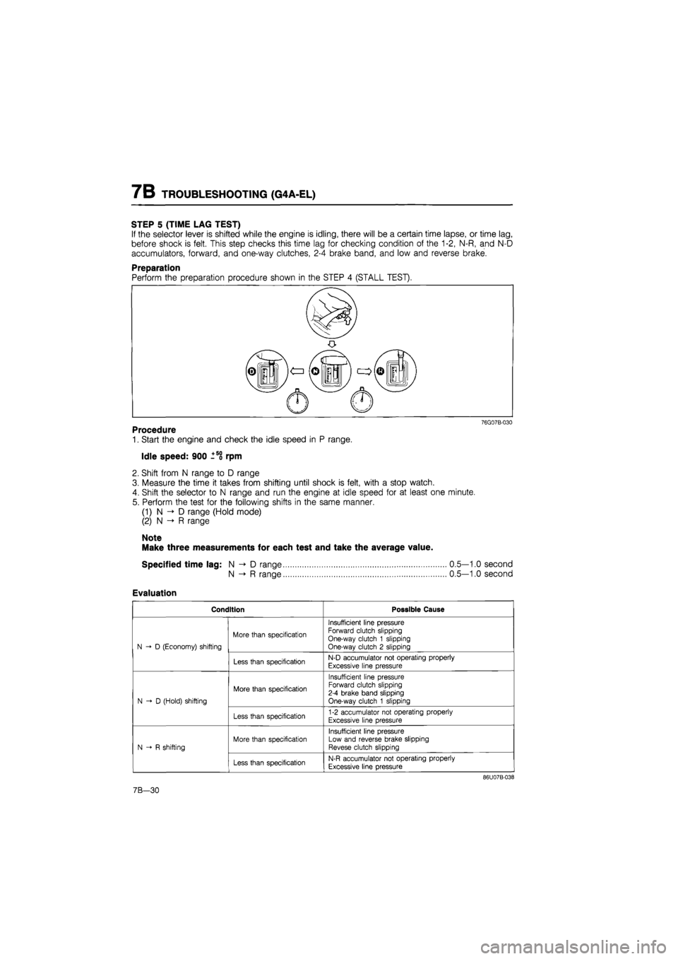
STEP 5 (TIME LAG TEST)
If the selector lever is shifted while the engine is idling, there will be a certain time lapse, or time lag,
before shock is felt. This step checks this time lag for checking condition of the 1-2, N-R, and N-D
accumulators, forward, and one-way clutches, 2-4 brake band, and low and reverse brake.
Preparation
76G07B-030
Procedure
1. Start the engine and check the idle speed in P range.
Idle speed: 900 ±58 rpm
2. Shift from N range to D range
3. Measure the time it takes from shifting until shock is felt, with a stop watch.
4. Shift the selector to N range and run the engine at idle speed for at least one minute.
5. Perform the test for the following shifts in the same manner.
(1) N D range (Hold mode)
(2) N -» R range
Note
Make three measurements for each test and take the average value.
Specified time lag: N -> D range
N -»• R range
Evaluation
Condition Possible Cause
N D (Economy) shifting
More than specification
Insufficient line pressure Forward clutch slipping One-way clutch 1 slipping One-way clutch 2 slipping N D (Economy) shifting
Less than specification N-D accumulator not operating properly
Excessive line pressure
N-D (Hold) shifting
More than specification
Insufficient line pressure Forward clutch slipping 2-4 brake band slipping One-way clutch 1 slipping N-D (Hold) shifting
Less than specification 1-2 accumulator not operating properly
Excessive line pressure
N R shifting
More than specification
Insufficient line pressure Low and reverse brake slipping Revese clutch slipping N R shifting
Less than specification N-R accumulator not operating properly
Excessive line pressure
86U07B-038
0.5—1.0 second
0.5—1.0 second
7B-30
Page 897 of 1865

TROUBLESHOOTING (G4A-EL) 7B
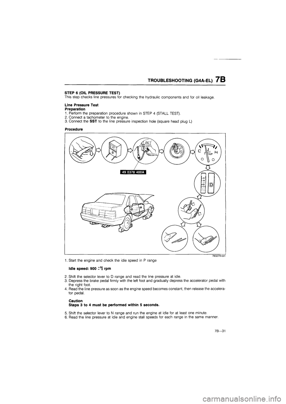
STEP 6 (OIL PRESSURE TEST)
This step checks line pressures for checking the hydraulic components and for oil leakage.
Line Pressure Test
Preparation
1. Perform the preparation procedure shown in STEP 4 (STALL TEST).
2. Connect a tachometer to the engine.
3. Connect the SST to the line pressure inspection hole (square head plug L)
Procedure
76G07B-031
1. Start the engine and check the idle speed in P range
Idle speed: 900 -so rpm
2. Shift the selector lever to D range and read the line pressure at idle.
3. Depress the brake pedal firmly with the left foot and gradually depress the accelerator pedal with
the right foot.
4. Read the line pressure as soon as the engine speed becomes constant, then release the accelera-
tor pedal.
Caution
Steps 3 to 4 must be performed within 5 seconds.
5. Shift the selector lever to N range and run the engine at idle for at least one minute.
6. Read the line pressure at idle and engine stall speeds for each range in the same manner.
7B—31