warning MAZDA 626 1987 Service Manual
[x] Cancel search | Manufacturer: MAZDA, Model Year: 1987, Model line: 626, Model: MAZDA 626 1987Pages: 1865, PDF Size: 94.35 MB
Page 625 of 1865

4C FUEL SYSTEM
^ Pulsation
damper
76G04C-121
Pulsation damper
—
Delivery pipe
76G04C-122
Fuel hose
,Fuel pump
-Intank filter
76G04C-123
Insulator
f f r—
/ 0 DM
•
II r
O - ring
Grommet
Manifold
Delivery pipe
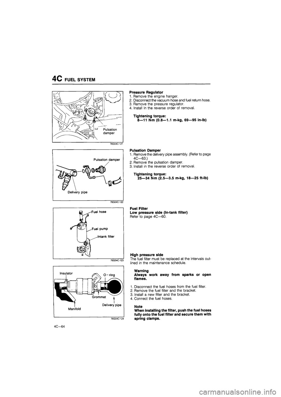
Pressure Regulator
1. Remove the engine hanger.
2. Disconnect the vacuum hose and fuel return hose.
3. Remove the pressure regulator.
4. Install in the reverse order of removal.
Tightening torque:
8—11 Nm (0.8—1.1 m-kg, 69—95 in-lb)
Pulsation Damper
1. Remove the delivery pipe assembly. (Refer to page
4C-63.)
2. Remove the pulsation damper.
3. Install in the reverse order of removal.
Tightening torque:
25—34 N m (2.5—3.5 m-kg, 18—25 ft-lb)
Fuel Filter
Low pressure side (In-tank filter)
Refer to page 4C—60.
76G04C-124
High pressure side
The fuel filter must be replaced at the intervals out-
lined in the maintenance schedule.
Warning
Always work away from sparks or open
flames.
1. Disconnect the fuel hoses from the fuel filter.
2. Remove the fuel filter and the bracket.
3. Install a new filter and the bracket.
4. Connect the fuel hoses.
Note
When installing the filter, push the fuel hoses
fully onto the fuel filter and secure them with
spring clamps.
4C-64
Page 627 of 1865

4C FUEL SYSTEM
Inspection
1. Check the fuel tank for cracks and corrosion.
2. If any defect is found, repair or replace the tank.
Warning
Before repairing, clean the fuel tank thorough-
ly with steam to remove all explosive fuel and
fumes.
Installation
Install in the reverse order of removal, referring to the installation note.
Torque Specifications
4C-66
76G04C-126
Page 631 of 1865

4C PRC SYSTEM
System Inspection
1. Connect the SST to the engine. (Refer to page
4C-53.)
2. Start the engine.
76G04C-131
Hi?
Jpll ssil
Water thermo sensor ^^^Tta^e air thermo sensor
76G04C-132
Operating time Fuel line pressure kPa (kg/cm2, psi)
After starting: for 120 sec. 235-275 (2.4-2.8, 34-40)
After 120 sec. 186-226 (1.9-2.3, 27-33)
3. Warm up the engine to normal operating temper-
ature and stop the engine.
Warning
Be careful when disconnecting the water ther-
mo sensor connector because the surround-
ing area is very hot.
4. Disconnect the water thermo sensor connector.
Connect a resistor (200 fl) to the sensor connector.
5. Heat the intake air thermo sensor to above specifi-
cation.
Specification: 30°C (86°F)....unleaded fuel
50°C (122°F)....leaded fuel
6. Restart the engine.
7. Check the fuel line pressure and operating times
as shown in the chart.
76G04C-133
Solenoid Valve (Pressure Regulator Control)
Inspection
1. Disconnect the vacuum hose from the vacuum
pipe.
2. Blow through the solenoid valve from vacuum hose
A.
3. Check that air flows from port B.
76G04C-134
4C—70
Page 639 of 1865

4C EGR SYSTEM (UNLEADED FUEL)
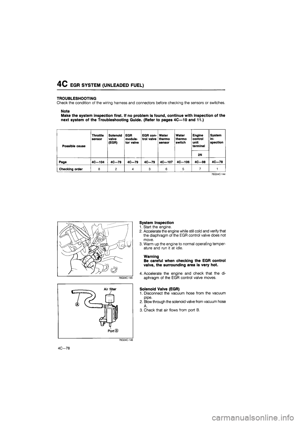
TROUBLESHOOTING
Check the condition of the wiring harness and connectors before checking the sensors or switches.
Note
Make the system inspection first. If no problem is found, continue with inspection of the
next system of the Troubleshooting Guide. (Refer to pages 4C—10 and 11.)
Possible cause
Throttle
sensor
Solenoid valve
(EGR)
EGR
modula-
tor valve
EGR con-trol valve
Water
thermo
sensor
Water
thermo switch
Engine control unit
terminal
System in-spection
2N
Page 4C—104 4C—78 4C—79 4C—79 4C—107 4C—106 4C—98 4C—78
Checking order 8 2 4 3 6 5 7 1
76G04C-144
System Inspection
1. Start the engine.
2. Accelerate the engine while still cold and verify that
the diaphragm of the EGR control valve does not
move.
3. Warm up the engine to normal operating temper-
ature and run it at idle.
Warning
Be careful when checking the EGR control
valve, the surrounding area is very hot.
4. Accelerate the engine and check that the di-
aphragm of the EGR control valve moves.
Solenoid Valve (EGR)
1. Disconnect the vacuum hose from the vacuum
pipe.
2. Blow through the solenoid valve from vacuum hose
A.
3. Check that air flows from port B.
76G04C-146
4C-78
Page 693 of 1865

4D FUEL SYSTEM
76G04D-047
76G04D-048
76G04D-049
FUEL FILTER
On-Vehicle Inspection
Check for water in the fuel filter. If present drain the
water. (Refer to page 4D—4.)
Replacement
Removal
1. Disconnect the water level sensor connector (ECE).
2. Remove the water level sensor. (ECE).
3. Remove the fuel filter cartridge.
Warning
Keep fire and open flame away from the fuel
area.
Installation
1. Apply fuel to the O-ring of the fuel filter cartridge
and install it onto the filter body.
2. Install the water level sensor (ECE).
3. Connect the water level sensor connector (ECE).
4. Bleed air from fuel filter. (Refer to page 4D—4.)
5. Check for fuel leakage.
SEDIMENTER (GENERAL)
On-Vehicle Inspection
Check for water in the sedimenter. If present, drain
the water. (Refer to page 4D—4.)
4D—22
Page 697 of 1865

4D FUEL SYSTEM
Removal and Installation
1. Remove in the sequence shown in the figure, referring to the removal note for specially marked parts.
2. Install in the reverse order of removal.
59—69 N-m
(6.0—7.0 m-kg, 43-51 ft-lb)
19—26
N m
(1.9—2.6
m-kg,
14—19 ft-lb) 25—29
N-m .5—3.0 m-kg, 18—22
ft-lb)
19—26 N-m
(1.9—2.6
m-kg,
14—19 ft-lb)
76G04D-063
1. Accelerator cable
2. Injection pipe
3. Fuel hose
4. Water hose
5. Fuel cut solenoid valve con-
nector
6. Pick-up coil connector
7. Boost air hose (RF-CX)
8. Injection pump pulley lock
nut
9. Injection pump
Removal note
Injection pipe
Warning
a) Catch leaking fuel with a rag when remov-
ing the injection pipes.
b) Keep fire and open flame away from the fuel
area.
Remove the injection pipes.
76G04D-064
4D—26
Page 702 of 1865

FUEL SYSTEM 4D
INJECTION NOZZLE
Removal
Remove in the sequence shown in the figure, referring to the removal note for the specially marked parts.
Removal note
Injection pipe
Warning
a) Catch leaking fuel leakage with a rag when
removing the injection pipes.
b) Keep fire and open flame away from the fuel
area.
Remove the injection pipes.
1. Injection pipe bracket
2. Injection pipe
3. Fuel leak pipe
4. Fuel injection nozzle
76G04D-072
4D—31
Page 705 of 1865

4D FUEL SYSTEM
FUEL TANK
Removal and Installation
1. Drain the fuel from the fuel tank.
2. Remove in the sequence shown in the figure, referring to the removal note for the specially marked
parts.
76G04D-081
1. Fuel level gauge connector 4. Joint hose 7. Fuel tank
2. Fuel main hose 5. Ventilation hose 8. Fuel tank pad
3. Fuel return hose 6. Breather hose
Removal note
Fuel main and return hoses
1. Remove the service hole cover from the body.
2. Disconnect the fuel main and return hoses and
plug them.
Warning
Keep fire and open flame away from the fuel
area.
4D—34
Page 729 of 1865

ALTERNATOR 5
TROUBLESHOOTING
Preliminary Check
1. Turn the ignition switch ON, and check that
the alternator warning light illuminates.
2. Start the engine, and check that the alternator warning light goes off.
76G05X-024
1. Alternator warning light always not illuminate
76G05X-025
2. Alternator warning light illuminates when engine running
76G05X-026
5-23
Page 730 of 1865

5 ALTERNATOR
3. Alternator warning light operates properly, but battery discharged
OK
NG OK
1
a) Poor connection between B terminal and positive battery cable
b) Poor connection of negative battery cable c) Poor connection between alternator connector (2-pin) and positive battery terminal d) Stator coil or diodes malfunction (Refer to page 5—32 or 5—34.)
Perform TEST 2. (Refer to page 5--25.)
NG
Perform TEST 3. (Refer to Dage 5--26.)
I OK
Perfrom TEST 4. (Refer to page 5--26.)
NG
Perform TEST 5 (F Refer to page 5—26)
OK
Alternator normal.
Check other electrical components.
NG
Alternator normal.
Check other electrical components.
Perform TEST 5. (Refer to page 5—26.)
OK
Stator coil, diode, main fuse, or wiring har-ness between B ternimal and battery mal-function.
(Refer to page 5—32 or 5—34.)
IC regulator, bush, or rotor coil malfunction. (Refer to page 5—32 or 5—33)
NG
76G05X-027
4. Battery overcharged
Less than 14.1V
(At 20°C, 68°F)
More than 14.7V
(At 20oC,68°F)
IC regulator malfunction,
Perform TES T 6. (Refer to page 5—27.)
NG OK
Wiring harness malfunction.
76G05X-028
5—24