warning MAZDA 626 1987 User Guide
[x] Cancel search | Manufacturer: MAZDA, Model Year: 1987, Model line: 626, Model: MAZDA 626 1987Pages: 1865, PDF Size: 94.35 MB
Page 148 of 1865

1 B ON-VEHICLE MAINTENANCE (CYLINDER HEAD)
1. Center cover
2. High-tension lead and spark plug
3. Accelerator cable
4. Air intake pipe assembly
5. Fuel hose
6. Upper radiator hose
7. Heater hose
8. Brake vacuum hose
9. Canister hose (Unleaded fuel)
10. Engine harness connector and ground
11. EGR pipe (Unleaded fuel)
12. A/C compressor and bracket
13. Exhaust manifold insulator
14. Exhaust pipe
15. Exhaust manifold
16. Intake manifold bracket
17. Intake manifold assembly
18. Distributor
19. Engine mount stay
20. Upper timing belt cover
21. Timing belt tensioner spring
22. Timing belt
23. Cylinder head cover
24. Cylinder head and gasket
76G01B-030
Removal note
Fuel hose
Warning
a) Cover the hose with a rag because fuel will
spray out when disconnecting.
b) Keep sparks and open flame away from the
fuel area.
Plug the disconnected hoses to avoid fuel leakage.
86U01X-032
Timing belt
1. Before removing the timing belt, turn the crankshaft
to align the mating marks of the camshaft pulleys
with the seal plate timing mark.
Note
For intake side camshaft pulley, align "I"
mark.
For exhaust side camshaft pulley, align "E"
mark.
76G01B-031
2. Loosen the timing belt tensioner lock bolt.
3. Shift the tensioner outward as far as possible, then
temporarily tighten it.
76G01B-034
1B—17
Page 153 of 1865

1B REMOVAL
REMOVAL
Warning: Release the fuel pressure. (Refer to Section 4C.)
1. Disconnect the negative battery cable.
2. Drain the engine oil and coolant.
3. Remove in the sequence shown in the figure referring to the removal note for specially marked parts.
76G01B-036
1B—22
Page 154 of 1865

REMOVAL 1B
1. Battery and battery carrier
2. Air cleaner assembly
3. High-tension lead
4. Accelerator cable
5. Fuel hose
6. Radiator hose
7. Radiator harness
8. Radiator and electric fan
9. EGI harness
10. Engine harness
11. Brake vacuum hose
12. Canister hose (Unleaded
fuel)
13. Heater hose
14. Transaxle harness
15. Speedometer cable
16. Clutch release cylinder
17. Drive belt
18. A/C compressor and
bracket
19. P/S oil pump
20. Engine side cover
21. Front wheel
22. Tie-rod end
23. Stabilizer control rod
24. Lower arm bushing
25. Driveshaft
26. Change rod
27. Extension bar
28. Exhaust pipe
29. Engine mount
30. Engine and transaxle
31. Transaxle
76G01B-037
Removal Note
Fuel hose
Warning
a) Cover the hose with a rag because fuel will
spray out when disconnecting.
b) Keep sparks and open flame away from the
fuel area.
Plug the disconnected hoses to avoid fuel leakage.
76G01A-11£
P/S pump, A/C compressor
Remove the P/S pump and A/C compressor with the
hoses still connected to them, secure the pump and
compressor as shown in the figure.
67U01X-029
Driveshaft
Remove the driveshafts. (Refer to Section 9.) Slide
the SST into the transaxle.
86U01X-060
1B—23
Page 205 of 1865

1B INSTALLATION
ENGINE INSTALLATION
Install the engine and transaxle assembly.
Warning: Be sure the vehicle is securely supported.
Torque Specifications
67—93
N m
(6.8—9.5 m-kg, 49—69 ft-lb)
85—117
N m
(8.7—11.9 m-kg, 63—86 ft-lb)
8—11 N-m (80—110 cm-kg, 69—95 in-lb)
8-11 N-m (80—110 cm-kg, 69—95 In-lb)
[;> )
16—27
N-m
(1.6—2.8 m-kg, 12—20 ft-lb)
37—63 N-m (3.8—6.4 m-l 27—46 ft-ll
37—52 N-m (3.8—5.3 m-kg 27—38 ft-lb)
64—89 N-m (6.5—9.1 m-kg, 47—66 ft-lb)
36—54 N-m (3.7—5.5 m-kg, 27—40 ft-lb)
-31—46 N-m (3.2—4.7 m-kg, 23—34 ft-lb)
31—46 N-m (3.2-4.7 m-kg, 23—34 ft-lb)
39—59 N-m (4.0—6.0 m-kg, 29—43 ft-lb)
8—11 N-m (80—110 cm-kg, 69—95 in-lb)
31—46 N-m (3.2—4.7 m 23—34 ft-lb)
19—25 N-m (1.9—2.6 m-kg, 14-
19—25 N-m (1.9—2.6 m
16—23 N-m (1.6—2.3 m-l
5—7 N-m (50—70 cm-kg, 43—61 in-lb)
-16—23 N-m (1.6—2.3 m-kg, 12—17 ft-lb)
9—13 N-m (90—130 cm-kg, 78—113 In-lb)
29—44 N-m (3.0—4.5 m-kg, 22—33 ft-lb)
,68—118 N-m .0—12.0 m-kg 65—87 ft-lb)
43-54 N-m (4.4—5.5 m-kg, 32-40 tl-lb)
8—11
N-m
(80—110 cm-kg, 69—95 In-lb)
86U01X-180
1B—74
Page 218 of 1865

1C TUNE-UP PROCEDURE
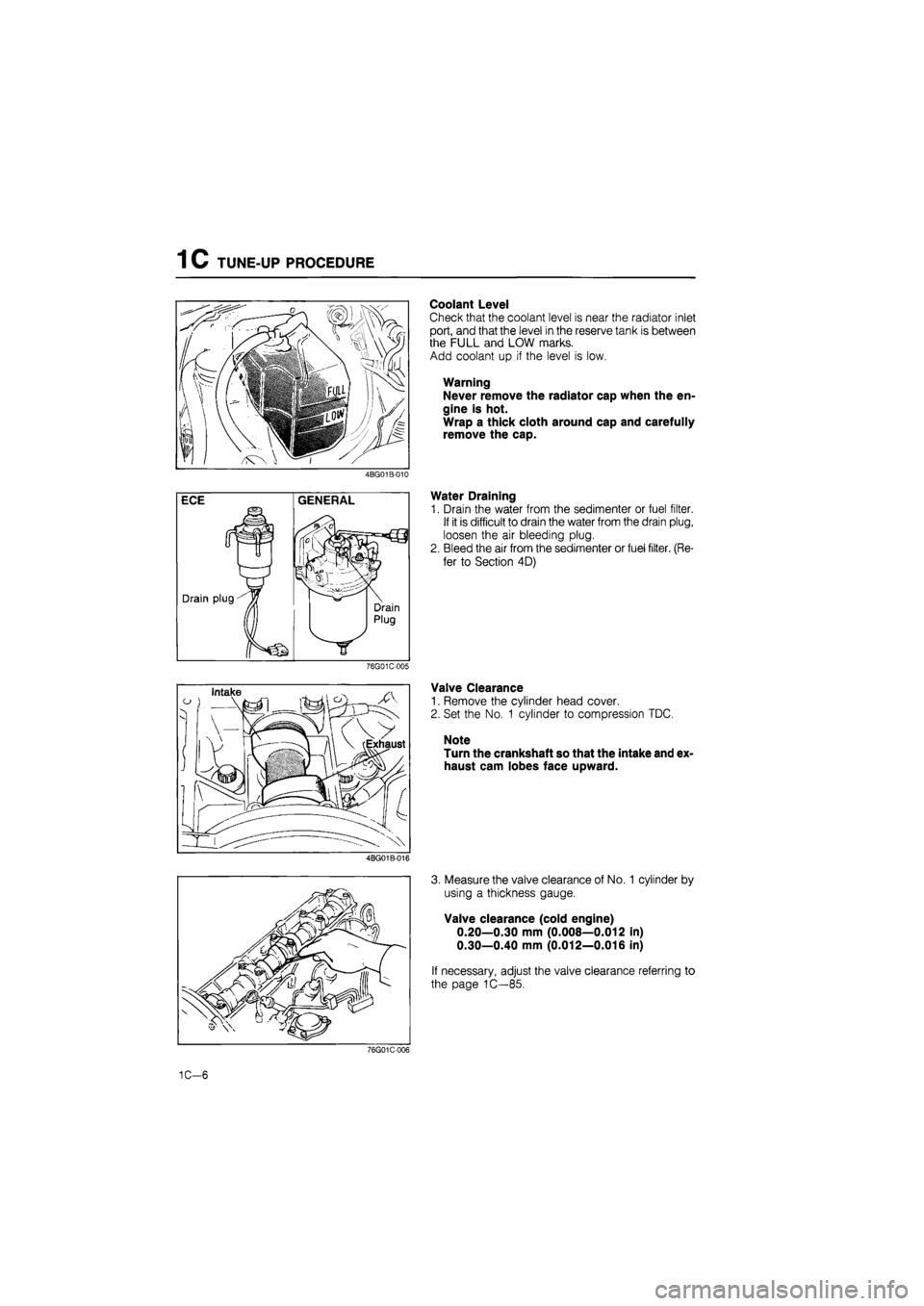
Coolant Level
Check that the coolant level is near the radiator inlet
port, and that the level in the reserve tank is between
the FULL and LOW marks.
Add coolant up if the level is low.
Warning
Never remove the radiator cap when the en-
gine is hot.
Wrap a thick cloth around cap and carefully
remove the cap.
4BG01B-010
Water Draining
1. Drain the water from the sedimenter or fuel filter.
If it is difficult to drain the water from the drain plug,
loosen the air bleeding plug.
2. Bleed the air from the sedimenter or fuel filter. (Re-
fer to Section 4D)
76G01C-005
Valve Clearance
1. Remove the cylinder head cover.
2. Set the No. 1 cylinder to compression TDC.
Note
Turn the crankshaft so that the intake and ex-
haust cam lobes face upward.
4BG01B-016
3. Measure the valve clearance of No. 1 cylinder by
using a thickness gauge.
Valve clearance (cold engine)
0.20—0.30 mm (0.008—0.012 in)
0.30—0.40 mm (0.012—0.016 in)
If necessary, adjust the valve clearance referring to
the page 1C—85.
76G01C-006
1C-6
Page 229 of 1865

ON-VEHICLE MAINTENANCE (CYLINDER HEAD) 1 C
Removal note
Fuel hose
Warning
a) Cover the hose with a rag because fuel will
spray out when disconnecting.
b) Keep fire and open flame away from the fuel
area.
Plug the disconnected hoses to avoid fuel leakage.
76G01C-033
2. Hold the camshaft with a wrench (29 mm, 1.14 in)
and loosen the camshaft pulley lock bolt.
Caution
Do not damage the cylinder head edge with
the wrench.
4BG01B-044
3. Separate the camshaft pulley from the camshaft
with the SST.
Caution
Do not hit the camshaft pulley with a hammer.
Rear camshaft pulley
Remove the rear camshaft pulley in the same man-
ner used for camshaft pulley.
76G01C-044
1C—17
Page 244 of 1865

1C REMOVAL
76G01C-244
76G01C-072
67U01X-029
Removal Note
Fuel hose
Warning
a) Cover the hose with a rag because fuel will
spray out when disconnecting.
b) Keep fire and open flame away from the fuel
area.
After disconnecting the fuel hoses, plug them to avoid
fuel leakage.
Clutch release cylinder
Remove the clutch release cylinder with the pipe still
connected; then avoid the cylinder.
P/S pump, A/C compressor
Remove the P/S pump and A/C compressor with the
hoses still connected to them, secure the pump and
compressor as shown in the figure.
Driveshaft
Remove the driveshafts. (Refer to Section 9.) Slide
the SST into the transaxle.
86U01X-060
1C-32
Page 304 of 1865

1C INSTALLATION
ENGINE INSTALLATION
Install the engine and transaxle assembly.
Warning: Be sure the vehicle is securely supported.
Torque Specifications
67-93 N-m {6.6—9.5 m-kg, 49—69 ft-Sb)
8—11 Nm (80—110 cm-kg,„ 69—95 in-lb)
85—117 N m (8.7—11.9 m-kg, 63—G6 ft-lb) S—11 N-m (80—110em-kg, 69—95 In-lb)
5—7 N-m (50—70 cm-kg, 43—61 in-lb)
67—93 N-m (6,8—9,5 m-kg, 49—69 ft-lb)
55—80 N-m (5.6—8.2 m-kg, 41—59 ft-lb)
8—11 N-m (80—110 cm-kg, 69—95 in-lb)
43—62 N-m (4.3—6.3 m-kg, 14—22 ft-lb)
7—10 N-m (70—100 cm-kg, 60—86 in-lb)
37—52 N-m (3.6—5.3 m-kg, 27—38 ft-lb)
34—49 N-m (3.5—5.0 m-kg, 25—36 ft-lb)
31—40 N-m 9 (3.2-4.1 m-kg, 23—30 ft-lb)
'8—11 N-m (80—110 cm-kg, 69—95 in-lb)
19—26 N-m (1.9—2.6 m-kg, 14—19 ft-lb)
29—44 N-m (3.0—4.5 m-kg, 22—33 ft-lb)
43—54 N-m (4.4—5.5 m-kg, 32—40 ft-lb)
-IS* 88—118 N-m ^-(9.0—12.0 m-kg, 65—87 ft-lb) 8—11 N-m (80—110 cm-kg, 69—95 In-lb)
86U01X-180
1C—92
Page 315 of 1865

2 A TROUBLESHOOTING GUIDE
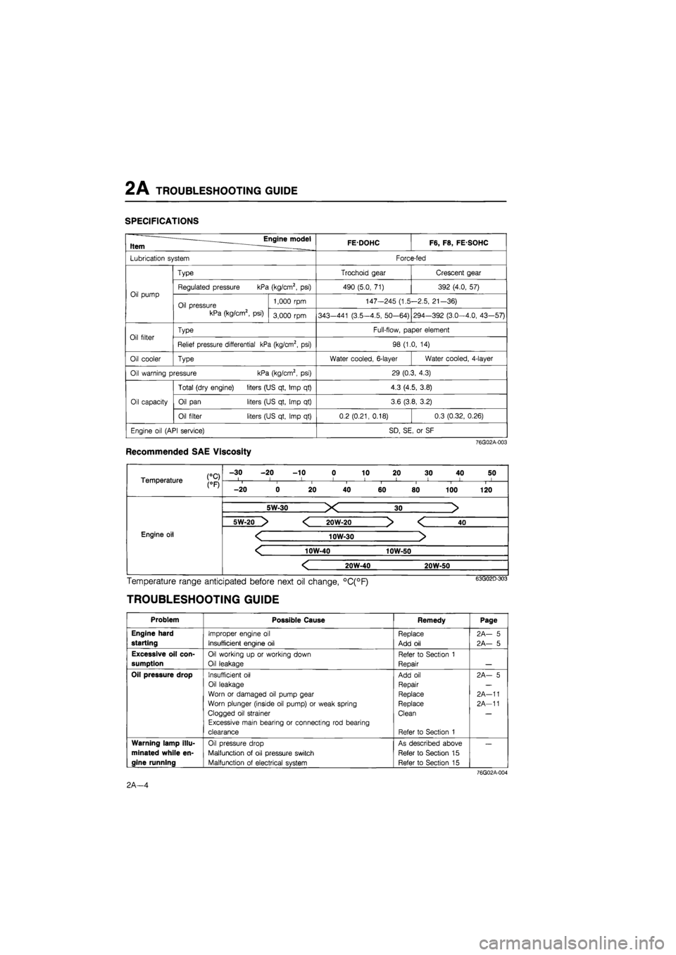
SPECIFICATIONS
Engine model Item . FEDOHC F6, F8, FE SOHC
Lubrication system Force-fed
Oil pump
Type Trochoid gear Crescent gear
Oil pump Regulated pressure kPa (kg/cm2, psi) 490 (5.0, 71) 392 (4.0, 57) Oil pump
Oil pressure kPa (kg/cm2, psi)
1,000 rpm 147-245 (1.5-2.5, 21-36) Oil pump
Oil pressure kPa (kg/cm2, psi) 3,000 rpm 343—441 (3.5-4.5, 50-64) 294-392 (3.0-4.0, 43—57)
Oil filter Type Full-flow, paper element Oil filter Relief pressure differential kPa (kg/cm2, psi) 98 (1.0, 14)
Oil cooler Type Water cooled, 6-layer Water cooled, 4-layer
Oil warning pressure kPa (kg/cm2, psi) 29 (0.3, 4.3)
Oil capacity
Total (dry engine) liters (US qt, Imp qt) 4.3 (4.5, 3.8)
Oil capacity Oil pan liters (US qt, Imp qt) 3.6 (3.8, 3.2) Oil capacity
Oil filter liters (US qt, Imp qt) 0.2 (0.21, 0.18) 0.3 (0.32, 0.26)
Engine oil (API service) SD, SE, or SF
76G02A-003
Recommended SAE Viscosity
Temperature j0pj
-30 -20 -10 0 10 20 30 40 50 I l I I 1 < ! I I Temperature j0pj i i i i I i 1 1
-20 0 20 40 60 80 100 120
Engine oil Engine oil
5W-30 X 30 >
Engine oil Engine oil
5W-20 > < 20W-20 > < 40
Engine oil < 10W-30 > Engine oil
< 10W-40 10W-50
Engine oil Engine oil
< 20W-40 20W-50
Engine oil
Temperature range anticipated before next oil change, °C(°F)
TROUBLESHOOTING GUIDE
Problem Possible Cause Remedy Page
Engine hard
starting
Improper engine oil
Insufficient engine oil
Replace
Add oil
2A— 5
2A— 5
Excessive oil con-
sumption
Oil working up or working down
Oil leakage
Refer to Section 1
Repair
Oil pressure drop Insufficient oil
Oil leakage
Worn or damaged oil pump gear
Worn plunger (inside oil pump) or weak spring
Clogged oil strainer
Excessive main bearing or connecting rod bearing
clearance
Add oil
Repair
Replace
Replace
Clean
Refer to Section 1
2A- 5
2A-11
2A-11
Warning lamp illu-
minated while en-
gine running
Oil pressure drop
Malfunction of oil pressure switch
Malfunction of electrical system
As described above
Refer to Section 15
Refer to Section 15
76G02A-004
2A—4
Page 316 of 1865

INSPECTION, ENGINE OIL 2A
86U02X-004
INSPECTION
ENGINE OIL
1. Be sure the vehicle is on level ground.
2. Warm up the engine to normal operating temper-
ature and stop it.
3. Wait for five minutes.
4. Remove the oil level gauge and check the oil lev-
el and condition.
5. Add or replace oil if necessary.
Note
The distance between the L and F marks on
the level gauge represents 1.0 liter (1.06 US
qt, 0.88 Imp qt).
OIL PRESSURE
1. Remove the oil pressure switch.
69G02A-006
76G02A-005
86U02X-006
2. Screw the SST into the pressure switch installa-
tion hole.
3. Warm up the engine to normal operating tem-
perature.
4. Run the engine at 3,000 rpm, and note the gauge
reading.
Oil pressure:
343—441 kPa
(3.5—4.5 kg/cm2, 50—64 psi)...DOHC 2g4 392 kPa
(3.0—4.0 kg/cm2, 43—57 psi)...SOHC
5. If the pressure is not as specified, check for the
cause, and repair if necessary.
(Refer to Troubleshooting Guide.)
ENGINE OIL
REPLACEMENT
1. Warm up the engine to the normal operating tem-
perature and stop it.
2. Remove the oil filler cap and the oil pan drain plug.
3. Drain the oil into a suitable container.
Warning
Be careful when draining, the oil is very hot.
2A-5