lights MAZDA 626 1987 User Guide
[x] Cancel search | Manufacturer: MAZDA, Model Year: 1987, Model line: 626, Model: MAZDA 626 1987Pages: 1865, PDF Size: 94.35 MB
Page 885 of 1865

TROUBLESHOOTING (G4A-EL) 7B
79G07C-068
Drive at 50
km/h
(31
mph)
Kick-down
Stop
the
vehicle
79G07C-069
After-repair Procedure
1. Cancel the memory of malfunctions by disconnect-
ing the negative battery terminal for at least five sec-
onds, then reconnect it.
2. Remove the EC-AT tester if it is connected.
3. Drive the vehicle at 50 km/h (31 mph), then de-
press the accelerator pedal fully to activate kick-
down. Stop the vehicle gradually.
KICK goimsv
BRAKE LIGHTS*
CRUISE CONTROL
C V,. DEPRESS FULL*
Ox
azsa
ORUti rpn
"J
i"
•
rm uu
£ZL ofF
4. Reconnect the EC-AT tester to the 6-pin service
connector.
5. Ground the 1 -pin service connector with a jumper
wire.
6. Turn the ignition switch ON.
7. Check that no code numbers are displayed.
79G07C-070
Inspection Procedure
No. 06 code display (Vehicle speed sensor)
76G07B-017
7B-19
Page 929 of 1865

ELECTRICAL SYSTEM COMPONENTS 7B
Economy position
Power position • POWER
•ECONO
76G07B-066
86U07B-049
86U07B-050
ELECTRICAL
SYSTEM COMPONENTS
MODE SWITCH (G4A-EL)
Inspection of Operation
1. Turn the ignition switch ON.
2. Check that the mode indicator illuminates at each
model.
3. If it is not working properly, check terminal voltage
of mode switch.
Inspection of Continuity
1. Disconnect the mode switch.
2. Turn the ignition switch ON and light switch OFF.
3. Check the voltage between each terminal and
ground.
Mode Voltage Mode a b d e f
Power Approx. 12V
Below 1.5 V Below 1.5 V Below 1.5 V Below 1.5 V
Economy Below
1.5 V
Below
1.5 V Below 1.5 V
Below
1.5 V
Approx.
12V
4.
If
correct, check for continuty between the terminal.
Inspection of Terminal Voltage
1. Disconnect the mode switch connector.
2. Check continuity of the terminals.
Mode
Economy
Power
Connector terminal
O
O
f
o
-o
o
o
-o
-o
O—O: Indicates continuity
3. If not correct, replace the mode switch.
HOLD SWITCH (G4A-EL)
Inspection of Operation
1. Turn the ignition switch ON.
2. Check that the hold indicator illuminates while
switch depressed. Release the switch and mode
indicator lights are out.
3. If it is not working properly, check terminal voltage
of hold switch.
76G07B-067
7B—63
Page 1137 of 1865

ELECTRIC COMPONENTS 7C
76G07C-036
76G07C-037
76G07C-038
ELECTRIC COMPONENTS
INHIBITOR SWITCH
Inspection
1. Check that engine starts only at P and N range.
2. Check that the backup lights illuminate in R range
with the ignition switch ON.
3. If the inhibitor switch is not operating properly, dis-
connect it and check the continuity between the
terminals.
Connection guide
Position
N
D, 1, 2
Connector terminal
-O
O -O
-O
O—O: Indicates continuity
4. If not correct, replace the inhibitor switch.
KICK-DOWN SWITCH
Inspection of Terminal Voltage
1. Turn the ignition switch ON.
2. Check the voltage at terminal (V) with a voltmeter.
Depressing stroke Terminal voltage
7/8-8/8 (Full) Approx. 12 V
0-7/8 Below 1,5V
3. If not correct, check the wiring harness or switch,
or adjust the switch position.
Inspection of Switch
1. Disconnect the kick-down switch connector.
2. Check for continuity of the switch with an
ohmmeter.
Switch Continuity
Pushed Yes
Released No
3. If not correct, replace the kick-down switch.
83U07B-060
7C—23
Page 1479 of 1865

ANTI-LOCK BRAKE SYSTEM (ABS) 1 1
86U11X-1C
Q-08
Q-08
Fail-safe relay
B B BG
(Q-08)(Q-09)
V
BL BR
Motor relay
B BR (Q-09)
LO RY
View from male-pin side
86U11X-167
76G11X-096
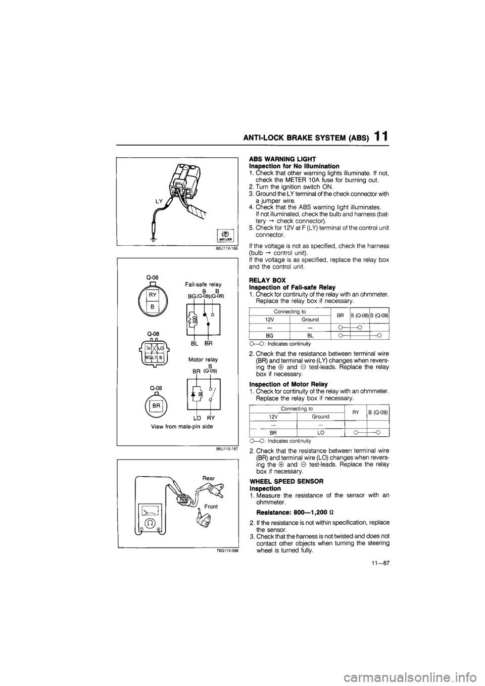
ABS WARNING LIGHT
Inspection for No Illumination
1. Check that other warning lights illuminate. If not,
check the METER 10A fuse for burning out.
2. Turn the ignition switch ON.
3. Ground the LY terminal
of
the check connector with
a jumper wire.
4. Check that the ABS warning light illuminates.
If not illuminated, check the bulb and harness (bat-
tery -» check connector).
5. Check for 12V at F (LY) terminal of the control unit
connector.
If the voltage is not as specified, check the harness
(bulb control unit).
If the voltage is as specified, replace the relay box
and the control unit.
RELAY BOX
Inspection of Fail-safe Relay
1. Check for continuity of the relay with an ohmmeter.
Replace the relay box if necessary.
Connecting to BR B (Q-08) B (Q-09) 12V Ground BR B (Q-08) B (Q-09)
— — O— —O
BG BL O— —O
O—O: Indicates continuity
2. Check that the resistance between terminal wire
(BR) and terminal wire (LY) changes when revers-
ing the © and © test-leads. Replace the relay
box if necessary.
Inspection of Motor Relay
1. Check for continuity of the relay with an ohmmeter.
Replace the relay box if necessary.
Connecting to RY B (Q-09) 12V Ground RY B (Q-09)
-—
BR LO o— O
O—O: Indicates continuity
2. Check that the resistance between terminal wire
(BR) and terminal wire (LO) changes when revers-
ing the © and © test-leads. Replace the relay
box if necessary.
WHEEL SPEED SENSOR
Inspection
1. Measure the resistance of the sensor with an
ohmmeter.
Resistance: 800—1,200 0
2. If the resistance is not within specification, replace
the sensor.
3. Check that the harness is not twisted and does not
contact other objects when turning the steering
wheel is turned fully.
11-87
Page 1552 of 1865

14
BONNET 14— 2
STRUCTURAL VIEW 14— 2
REMOVAL 14— 3
INSTALLATION 14— 4 ADJUSTMENT 14— 4 TRUNK LID 14— 5 STRUCTURAL VIEW (SEDAN AND COUPE/MX-6) 14— 5 REMOVAL 14— 6 INSTALLATION 14— 7 ADJUSTMENT 14— 8
REAR HATCH 14— 9 STRUCTURAL VIEW 14— 9 REMOVAL 14— 10 INSTALLATION 14— 12 ADJUSTMENT 14— 12 FRONT DOORS 14—13
STRUCTURAL VIEW 14— 13
REMOVAL 14—15
INSTALLATION 14—17 ADJUSTMENT 14— 18 REAR DOORS 14—19 STRUCTURAL VIEW 14— 19 REMOVAL 14— 20
INSTALLATION 14— 21 ADJUSTMENT 14— 22 FRONT BUMPER 14— 23
STRUCTURAL VIEW 14—23 REMOVAL 14— 24 INSTALLATION 14—24 REAR BUMPER 14— 25
STRUCTURAL VIEW 14— 25 REMOVAL 14— 26
INSTALLATION 14— 26 RADIATOR GRILLE 14— 27 REMOVAL AND INSTALLATION 14— 27 HEADLIGHT AND COMBINATION LIGHT 14— 28 REMOVAL AND INSTALLATION 14— 28
AIMING 14— 31 REAR COMBINATION LIGHTS 14— 32 REMOVAL AND INSTALLATION 14— 32
REPLACEMENT OF REAR COMBINATION LIGHT LENS 14— 33
LICENSE PLATE LIGHT AND CARGO ROOM LIGHT 14— 35 REMOVAL AND INSTALLATION 14— 35
INTERIOR LIGHT AND MAP LIGHT 14- 36 REMOVAL AND INSTALLATION 14— 36
MOLDING AND GARNISH 14— 37
STRUCTURAL VIEW 14— 37 WINDSHIELD MOLDING 14— 38 WINDSHIELD LOWER MOLDING 14— 38 DRIP MOLDING 14— 38 BELT LINE MOLDING 14— 38 REAR WINDOW SIDE MOLDING (SEDAN) .14— 39 REAR WINDOW LOWER MOLDING
(SEDAN AND COUPE/MX-6) 14— 39 REAR WINDOW UPPER MOLDING 14— 39
BONNET MOLDING
(SEDAN AND HATCHBACK) 14— 39 QUARTER WINDOW MOLDING (COUPE/MX-6) 14— 40 QUARTER WINDOW MOLDING
(HATCHBACK) 14—40 QUARTER WINDOW MOLDING (SEDAN)... 14— 40 REAR WINDOW SIDE MOLDING (COUPE/MX-6) 14— 40
TRUNK LID MOLDING (SEDAN AND HATCHBACK) 14— 41
CENTER PILLAR GARNISH
(SEDAN AND HATCH BAC K/MX-6) 14— 41 REAR FINISHER (COUPE/MX-6 AND SEDAN) 14— 41 REAR FINISHER (HATCHBACK) 14— 41
SAIL GARNISH 14— 42
SIDE PROTECTOR MOLDING 14— 42 DOOR MIRROR 14— 44 DISASSEMBLY 14— 44 ASSEMBLY 14— 44 TRUNK-LID LOCK REMOTE RELEASE 14— 45 REMOVAL AND INSTALLATION 14— 45 FUEL FILLER LID REMOTE RELEASE 14— 46
REMOVAL AND INSTALLATION 14— 46 WINDSHIELD GLASS 14—47 STRUCTURAL VIEW 14—47 REMOVAL 14— 48 INSTALLATION 14— 49 REAR WINDOW GLASS 14— 52
STRUCTURAL VIEW 14— 52 REMOVAL 14— 54
INSTALLATION 14— 55 REAR HATCH GLASS 14— 58 STRUCTURAL VIEW 14— 58 REMOVAL 14— 59 INSTALLATION 14— 59 QUARTER WINDOW GLASS 14— 62 STRUCTURAL VIEW 14— 62
REMOVAL 14— 64 INSTALLATION 14—64
HEADLINER 14- 67 STRUCTURAL VIEW 14—67 REMOVAL 14— 69 INSTALLATION 14— 72 INSTRUMENT PANEL 14— 73 STRUCTURAL VIEW 14— 73
INSTALLATION VIEW 14— 74
REMOVAL 14— 75 INSTALLATION 14— 80 SLIDING SUNROOF 14— 81 STRUCTURAL VIEW 14— 81 REMOVAL 14— 82 INSTALLATION 14— 85 WINDSHIELD WIPER 14— 91
STRUCTURAL VIEW 14— 91
REMOVAL 14— 92
INSTALLATION 14— 93 ADJUSTMENT 14— 93 REAR WINDOW WIPER 14—94 STRUCTURAL VIEW (HATCHBACK) 14— 94 REMOVAL 14— 95 INSTALLATION 14—95 ADJUSTMENT 14— 96
HEADLIGHT WASHER 14— 97 REMOVAL AND INSTALLATION 14— 97 SEAT 14— 98 STRUCTURAL VIEW 14— 98 INSPECTION 14—100 SEAT BELTS 14—101
STRUCTURAL VIEW 14—101 INSPECTION 14—101
UNDERBODY PROJECTED DIMENSIONS.... 14—102 UNDERBODY STRAIGHT-LINE DIMENSIONS 14—104 76G14X-001
Page 1583 of 1865

1 4 REAR COMBINATION LIGHTS
REAR COMBINATION LIGHTS
REMOVAL AND INSTALLATION
1. Disconnect the negative battery cable.
2. Remove in the sequence shown in the figure.
3. Install in the reverse order of removal.
76G14X-010
Hatchback
1. End trim
2. Nuts
3. Lens and body
4. Cover
5. Bulb: Turn signal light 21W
Brake and tail light 21W
Side marker light 5W
Sedan and Coupe/MX-6
1. End trim
2. Nuts
3. Lens and body
4. Cover
5. Bulb: Turn signal light 21W
Brake and tail light 21W
Side marker light 5W
14—32
Page 1584 of 1865

REAR COMBINATION LIGHTS 1 4
REPLACEMENT OF REAR COMBINATION LIGHT
LENS
1. Use a hot air blower to soften the "hot melt" (bond-
ing agent) around the lens.
86U14X-077
2. Remove the lens from the light housing by push-
ing the rear of the lens with a hammer handle or
round bar.
76U14X-034
3. Heat the light housing, and remove the "hot melt"
and any fragments of the lens.
Note
a) The "hot melt" should be reused if
possible.
b) If the "hot melt" can be reused, the follow-
ing step is unnecessary.
86U14X-078
4. Put Uni-sealer (8531 77 739) adhesive in the light
housing groove.
86U14X-079
14—33
Page 1585 of 1865

1 4 REAR COMBINATION LIGHTS
5. Fit the new lens onto the light housing. Press the
lens firmly so that it will adhere.
86U14X080
6. Immerse the combination light in water to check
for leaks.
76U14X-038
14—34
Page 1674 of 1865

CLUSTER SWITCH 15
e a
frtum
Illumination light
b
f
e -Q-
f d b d I f
Indicator light
76G15X-088
86U15X-018
g
TTTT
h f d b
from f „
IG SW
from a def. relay^
from ~ TWS unit
15 minules timer
To ground
h To panel
"controller
INSPECTION OF ROCKER TYPE
Hazard switch
1. Check for continuity between the terminals in each
position with an ohmmeter.
——____Terminal Position
^
a
b d
e
f
OFF
ON
-o
O
O:
Indicates continuity
2. If continuity is not as specified, replace the switch
or replace the light(s).
Defroster switch
1. Turn the ignition switch ON.
2. Push the defroster switch to ON, and check the
lights for lighting.
3. If the lights do not light, replace the lights.
4. Check that the switch goes off after 15 min from
switch ON.
5. Check the voltage between each terminal and a
body ground.
Position Terminal voltage
(V)
Position
b d f g h
OFF 0 12 12 0 12
ON 0 0 12 0 12
ON
(head light switch
ON) 0 0 12 2-12 12
OFF (head light switch
ON) 0 12 12 2-12 12
6. If the voltage of "d" terminal is 12V with switch off
but not OV with switch on, replace the defroster
switch.
If the voltage of "d" terminal is not 12V with switch
off, trouble is in defroster relay or harness.
If the voltages of the other terminals are not cor-
rect, trouble is in the other parts or harness.
86U15X-019
15—19
Page 1677 of 1865

15 METER
METER
STRUCTURAL VIEW
DIGITAL ELECTRONIC DISPLAY METER
ANALOG DISPLAY METER
76G15X-007
1. Speedometer 5. Warning and indicator lights
2. Tachometer 6. Tripmeter
3. Water temperature gauge 7. Twin tripmeter change switch
4. Fuel gauge 8. Fuel garge scale change switch
15—22