mirror MAZDA 626 1987 Workshop Manual
[x] Cancel search | Manufacturer: MAZDA, Model Year: 1987, Model line: 626, Model: MAZDA 626 1987Pages: 1865, PDF Size: 94.35 MB
Page 14 of 1865

0 PRE-DELIVERY INSPECTION
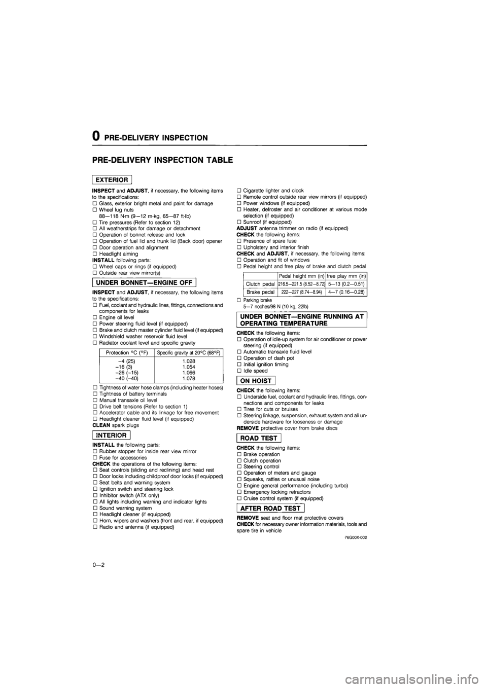
PRE-DELIVERY INSPECTION TABLE
EXTERIOR
INSPECT and ADJUST, if necessary, the following items
to the specifications:
• Glass, exterior bright metal and paint for damage
• Wheel lug nuts
88—118 N m (9—12 m-kg, 65—87 ft-lb)
• Tire pressures (Refer to section 12)
• All weatherstrips for damage or detachment
• Operation of bonnet release and lock
• Operation of fuel lid and trunk lid (Back door) opener
• Door operation and alignment
• Headlight aiming
INSTALL following parts:
• Wheel caps or rings (if equipped)
• Outside rear view mirror(s)
UNDER BONNET—ENGINE OFF
INSPECT and ADJUST, if necessary, the following items
to the specifications:
• Fuel, coolant and hydraulic lines, fittings, connections and
components for leaks
• Engine oil level
• Power steering fluid level (if equipped)
• Brake and clutch master cylinder fluid level (if equipped)
• Windshield washer reservoir fluid level
• Radiator coolant level and specific gravity
Protection °C (°F) Specific gravity at 20°C (68°F)
-4 (25) 1.028
-16(3) 1.054
-26 (-15) 1.066 -40 (-40) 1.078
• Tightness of water hose clamps (including heater hoses)
• Tightness of battery terminals
• Manual transaxle oil level
• Drive belt tensions (Refer to section 1)
• Accelerator cable and its linkage for free movement
• Headlight cleaner fluid level (if equipped)
CLEAN spark plugs
INTERIOR
INSTALL the following parts:
• Rubber stopper for inside rear view mirror
• Fuse for accessories
CHECK the operations of the following items:
• Seat controls (sliding and reclining) and head rest
• Door locks including childproof door locks (if equipped)
• Seat belts and warning system
• Ignition switch and steering lock
• Inhibitor switch (ATX only)
• All lights including warning and indicator lights
• Sound warning system
• Headlight cleaner (if equipped)
• Horn, wipers and washers (front and rear, if equipped)
• Radio and antenna (if equipped)
• Cigarette lighter and clock
• Remote control outside rear view mirrors (if equipped)
• Power windows (if equipped)
• Heater, defroster and air conditioner at various mode
selection (if equipped)
• Sunroof (if equipped)
ADJUST antenna trimmer on radio (if equipped)
CHECK the following items:
• Presence of spare fuse
• Upholstery and interior finish
CHECK and ADJUST, if necessary, the following items:
• Operation and fit of windows
• Pedal height and free play of brake and clutch pedal
Pedal height mm (in) free play mm (in)
Clutch pedal 216.5-221.5 (8.52-8.72) 5-13 (0.2-0.51)
Brake pedal 222-227 (8.74-8.94) 4-7 (0.16-0.28)
• Parking brake
5-7 noches/98 N (10 kg, 22lb)
UNDER BONNET—ENGINE RUNNING AT
OPERATING TEMPERATURE
CHECK the following items:
• Operation of idle-up system for air conditioner or power
steering (if equipped)
• Automatic transaxle fluid level
• Operation of dash pot
• Initial ignition timing
• Idle speed
ON HOIST
CHECK the following items:
• Underside fuel, coolant and hydraulic lines, fittings, con-
nections and components for leaks
• Tires for cuts or bruises
• Steering linkage, suspension, exhaust system and all un-
derside hardware for looseness or damage
REMOVE protective cover from brake discs
ROAD TEST"
CHECK the following items:
• Brake operation
• Clutch operation
• Steering control
• Operation of meters and gauge
• Squeaks, rattles or unusual noise
• Engine general performance (including turbo)
• Emergency locking retractors
• Cruise control system (if equipped)
AFTER ROAD TEST
REMOVE seat and floor mat protective covers
CHECK for necessary owner information materials, tools and
spare tire in vehicle
-76G00X-002
0-2
Page 944 of 1865

7B ON-VEHICLE MAINTENANCE
Installation
Install in the reverse order of removal referring to in-
stallation note.
Installation note
Control valve body
Install the control valve body.
Tightening torque: 11—15 N-m
(110—150 cm-kg, 95—130 in-lb)
86U07B-083
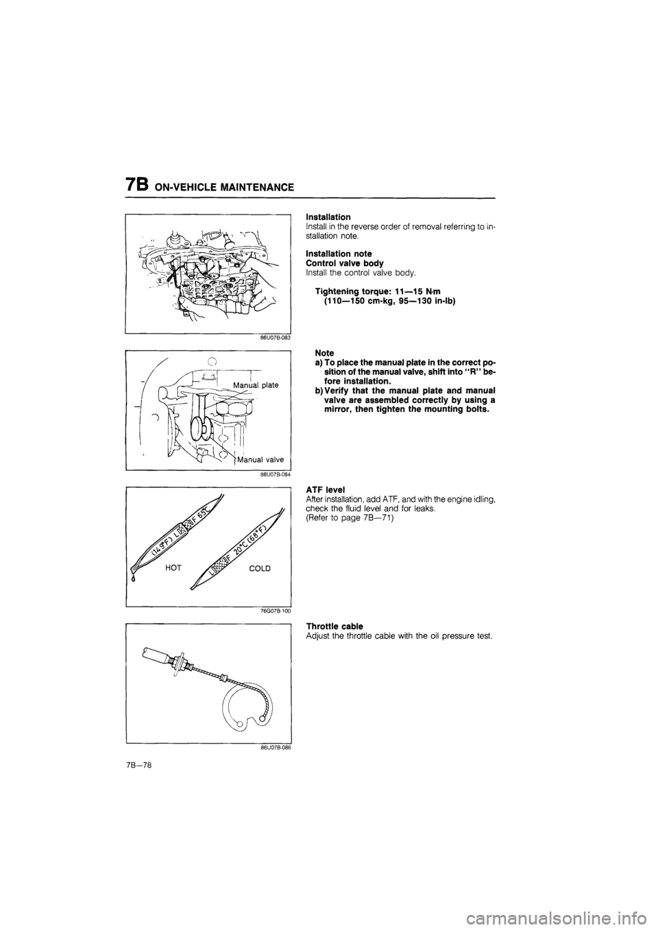
Note
a) To place the manual plate in the correct po-
sition of the manual valve, shift into "R" be-
fore installation.
b) Verify that the manual plate and manual
valve are assembled correctly by using a
mirror, then tighten the mounting bolts.
86U07B-084
w v
ATF level
After installation, add ATF, and with the engine idling,
check the fluid level and for leaks.
(Refer to page 7B—71)
76G07B-100
Throttle cable
Adjust the throttle cable with the oil pressure test.
86U07B-086
7B-78
Page 1552 of 1865

14
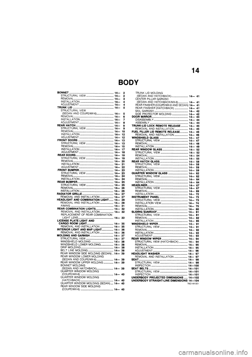
BONNET 14— 2
STRUCTURAL VIEW 14— 2
REMOVAL 14— 3
INSTALLATION 14— 4 ADJUSTMENT 14— 4 TRUNK LID 14— 5 STRUCTURAL VIEW (SEDAN AND COUPE/MX-6) 14— 5 REMOVAL 14— 6 INSTALLATION 14— 7 ADJUSTMENT 14— 8
REAR HATCH 14— 9 STRUCTURAL VIEW 14— 9 REMOVAL 14— 10 INSTALLATION 14— 12 ADJUSTMENT 14— 12 FRONT DOORS 14—13
STRUCTURAL VIEW 14— 13
REMOVAL 14—15
INSTALLATION 14—17 ADJUSTMENT 14— 18 REAR DOORS 14—19 STRUCTURAL VIEW 14— 19 REMOVAL 14— 20
INSTALLATION 14— 21 ADJUSTMENT 14— 22 FRONT BUMPER 14— 23
STRUCTURAL VIEW 14—23 REMOVAL 14— 24 INSTALLATION 14—24 REAR BUMPER 14— 25
STRUCTURAL VIEW 14— 25 REMOVAL 14— 26
INSTALLATION 14— 26 RADIATOR GRILLE 14— 27 REMOVAL AND INSTALLATION 14— 27 HEADLIGHT AND COMBINATION LIGHT 14— 28 REMOVAL AND INSTALLATION 14— 28
AIMING 14— 31 REAR COMBINATION LIGHTS 14— 32 REMOVAL AND INSTALLATION 14— 32
REPLACEMENT OF REAR COMBINATION LIGHT LENS 14— 33
LICENSE PLATE LIGHT AND CARGO ROOM LIGHT 14— 35 REMOVAL AND INSTALLATION 14— 35
INTERIOR LIGHT AND MAP LIGHT 14- 36 REMOVAL AND INSTALLATION 14— 36
MOLDING AND GARNISH 14— 37
STRUCTURAL VIEW 14— 37 WINDSHIELD MOLDING 14— 38 WINDSHIELD LOWER MOLDING 14— 38 DRIP MOLDING 14— 38 BELT LINE MOLDING 14— 38 REAR WINDOW SIDE MOLDING (SEDAN) .14— 39 REAR WINDOW LOWER MOLDING
(SEDAN AND COUPE/MX-6) 14— 39 REAR WINDOW UPPER MOLDING 14— 39
BONNET MOLDING
(SEDAN AND HATCHBACK) 14— 39 QUARTER WINDOW MOLDING (COUPE/MX-6) 14— 40 QUARTER WINDOW MOLDING
(HATCHBACK) 14—40 QUARTER WINDOW MOLDING (SEDAN)... 14— 40 REAR WINDOW SIDE MOLDING (COUPE/MX-6) 14— 40
TRUNK LID MOLDING (SEDAN AND HATCHBACK) 14— 41
CENTER PILLAR GARNISH
(SEDAN AND HATCH BAC K/MX-6) 14— 41 REAR FINISHER (COUPE/MX-6 AND SEDAN) 14— 41 REAR FINISHER (HATCHBACK) 14— 41
SAIL GARNISH 14— 42
SIDE PROTECTOR MOLDING 14— 42 DOOR MIRROR 14— 44 DISASSEMBLY 14— 44 ASSEMBLY 14— 44 TRUNK-LID LOCK REMOTE RELEASE 14— 45 REMOVAL AND INSTALLATION 14— 45 FUEL FILLER LID REMOTE RELEASE 14— 46
REMOVAL AND INSTALLATION 14— 46 WINDSHIELD GLASS 14—47 STRUCTURAL VIEW 14—47 REMOVAL 14— 48 INSTALLATION 14— 49 REAR WINDOW GLASS 14— 52
STRUCTURAL VIEW 14— 52 REMOVAL 14— 54
INSTALLATION 14— 55 REAR HATCH GLASS 14— 58 STRUCTURAL VIEW 14— 58 REMOVAL 14— 59 INSTALLATION 14— 59 QUARTER WINDOW GLASS 14— 62 STRUCTURAL VIEW 14— 62
REMOVAL 14— 64 INSTALLATION 14—64
HEADLINER 14- 67 STRUCTURAL VIEW 14—67 REMOVAL 14— 69 INSTALLATION 14— 72 INSTRUMENT PANEL 14— 73 STRUCTURAL VIEW 14— 73
INSTALLATION VIEW 14— 74
REMOVAL 14— 75 INSTALLATION 14— 80 SLIDING SUNROOF 14— 81 STRUCTURAL VIEW 14— 81 REMOVAL 14— 82 INSTALLATION 14— 85 WINDSHIELD WIPER 14— 91
STRUCTURAL VIEW 14— 91
REMOVAL 14— 92
INSTALLATION 14— 93 ADJUSTMENT 14— 93 REAR WINDOW WIPER 14—94 STRUCTURAL VIEW (HATCHBACK) 14— 94 REMOVAL 14— 95 INSTALLATION 14—95 ADJUSTMENT 14— 96
HEADLIGHT WASHER 14— 97 REMOVAL AND INSTALLATION 14— 97 SEAT 14— 98 STRUCTURAL VIEW 14— 98 INSPECTION 14—100 SEAT BELTS 14—101
STRUCTURAL VIEW 14—101 INSPECTION 14—101
UNDERBODY PROJECTED DIMENSIONS.... 14—102 UNDERBODY STRAIGHT-LINE DIMENSIONS 14—104 76G14X-001
Page 1564 of 1865

FRONT DOORS 1 4
FRONT DOORS
STRUCTURAL VIEW
86U14X-034
1. Power window switch
2. Regulator handle
3. Inner handle cover
4. Door trim
5. Door screen
6. Weatherstrip
7. Regulator (power type)
8. Regulator (manual type)
9. Key cylinder
10. Glass
11. Glass guide
12. Runchannel
13. Weatherstrip
14. Glass guide
15. Door checker
16. Door
17. Outer handle
18. Door mirror
19. Beltline molding
20. Weatherstrip
21. Sail inner garnish
14—13
Page 1565 of 1865

1 4 FRONT DOORS
1. Regulator handle
2. Arm rest
3. Power window switch
4. Inner handle cover
5. Door trim
6. Door screen
7. Weatherstrip
8. Regulator (power type)
9. Regulator (manual type)
10. Glass guide
11. Glass
12. Runchannel
13. Weatherstrip
14. Door
15. Door checker
16. Beltline molding
17. Weatherstrip
18. Door mirror
19. Outer handle
20. Key cylinder
21. Sail inner garnish
86U14X-035
14—14
Page 1589 of 1865

1 4 MOLDING AND GARNISH
WINDSHIELD MOLDING
Removal and Installation
1. Remove the windshield molding. (Refer to page
14-48)
2. Install the windshield molding. (Refer to page
14-51)
76G14X035
WINDSHIELD LOWER MOLDING
Removal and Installation
1. Remove the wiper arms.
2. Remove the lower molding screws and the lower
molding.
3. Install in the reverse order of removal.
86U14X-086
DRIP MOLDING
Removal and Installation
1. Insert a screwdriver between the roof rail and drip
molding and slightly loosen the end of the molding.
Note
Be careful not to scratch the molding.
2. Remove the molding by twisting upward with both
hands.
3. Install in the reverse order of removal.
86U14X-087
BELTLINE MOLDING
Removal and Installation
1. Remove the door mirror.
2. Remove the screw from the end of the beltline
molding, then pull the molding up to remove it.
3. Install in the reverse order of removal.
86U14X-088
14-38
Page 1595 of 1865

1 4 DOOR MIRROR
DOOR MIRROR
DISASSEMBLY l ,
1 Warm the frame and the mirror glass with a lamp
(500W) to approx. 70°C (158°F) for approx. 3
minutes.
2. Insert a scraper between the mirror glass and the
frame, then pry the mirror loose.
3. Remove any remaining adhesive.
ASSEMBLY
1. Warm the frame with a lamp.
2. Install the glass in the frame, then gently press it
in to secure it.
86U14X-107
14—44
Page 1598 of 1865

WINDSHIELD GLASS 1 4
WINDSHIELD GLASS
STRUCTURAL VIEW
86U14X-110
1. Rear view mirror 4. Front pillar trim
2. Sunvisor 5. Wiper arm
3. Front header trim 6. Lower molding
Note
Use window tool set (49 0305 870A) to remove and install the glass.
7. Front windshield molding
8. Windshield glass
9. Spacer
14—47
Page 1599 of 1865

1 4 WINDSHIELD GLASS
REMOVAL
1. Remove the rearview mirror, sunvisors, front pillar
trim, and front header trim.
2. Remove the wiper arms and lower molding.
3. Remove the front window molding.
86U14X-111
Protective tape
Piano wire
Caution
Before removing the sealant, apply adhesive
tape to the body and instrument panel to pro-
tect them from damage.
86U14X-112
86U14X-113
4. Make a small hole through the sealant.
5. Pass the piano wire through the hole.
6. Wind each end of the wire around a bar.
7. Pull the wire to and fro, and saw through the seal-
ant around the edge of the glass. Then remove the
glass.
Caution
a) Use a long sawing action to spread the work
over the whole length of wire to prevent it
from breaking.
b) Be careful that the wire does not rub on the
body or instrument panel.
Note
If the glass is not to be reused, a tool like that
shown in the figure may be used.
Insert the blade in the sealant, and pull on the bars.
86U14X-114
14—48
Page 1602 of 1865

WINDSHIELD GLASS 1 4
10. Align the alignment mark of the molding with that
on the lap of the glass and push the molding into
place along the top.
Caution
a) Apply primer with a brush to the bonding
area of the molding, and allow it to dry for
approx. 30 minutes.
b) Use a new window molding
86U14X-121
11. Insert the molding ends into the flanges of the lower
molding. Then push it in the along sides.
76G14X-045
86U14X-123
13. Attach the front header trim, pillar trim, sunvisors,
and rearview mirror.
86U14X-124
14—51