MAZDA MODEL CX-5 2017 Owner's Manual - RHD (UK, Australia) (in English)
Manufacturer: MAZDA, Model Year: 2017, Model line: MODEL CX-5, Model: MAZDA MODEL CX-5 2017Pages: 772, PDF Size: 19.35 MB
Page 381 of 772
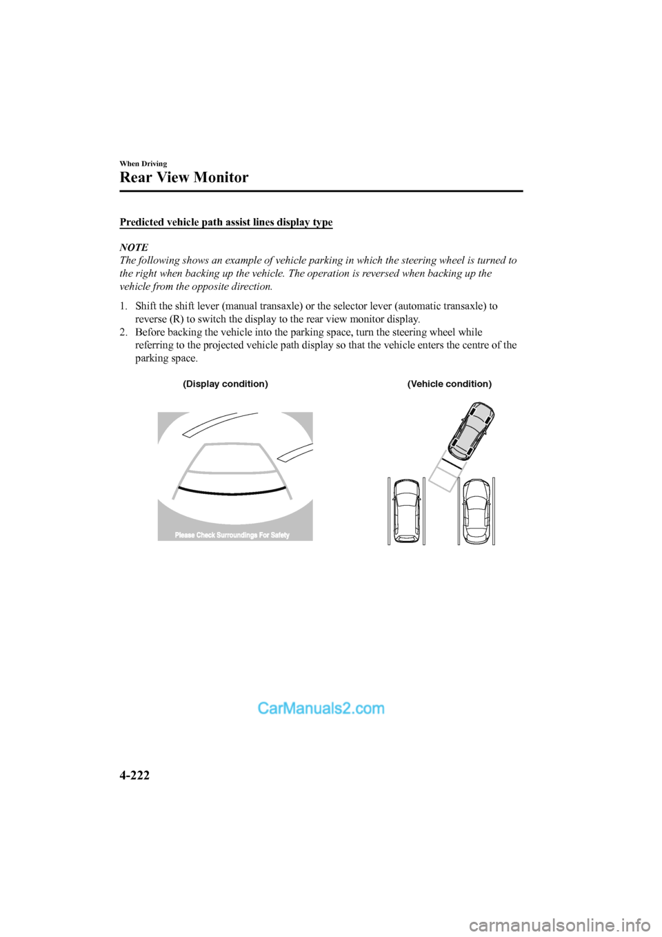
Predicted vehicle path assist lines display type
NOTE
The following shows an example of vehicle parking in which the steering wheel is turned to
the right when backing up the vehicle. The operation is reversed when backing up the
vehicle from the opposite direction.
1. Shift the shift lever (manual transaxle) or the selector leve r (automatic transaxle) to
reverse (R) to switch the displa y to the rear view monitor display.
2. Before backing the vehicle into the parking space, turn the steering wheel while
referring to the projected vehicle path display so that the veh icle enters the centre of the
parking space.
(Display condition) (Vehicle condition)
When Driving
Rear View Monitor
4-222
2017-6-7 7:51:19 Form No. CX-5 8FY4-EE-17E+L_Edition2
Page 382 of 772
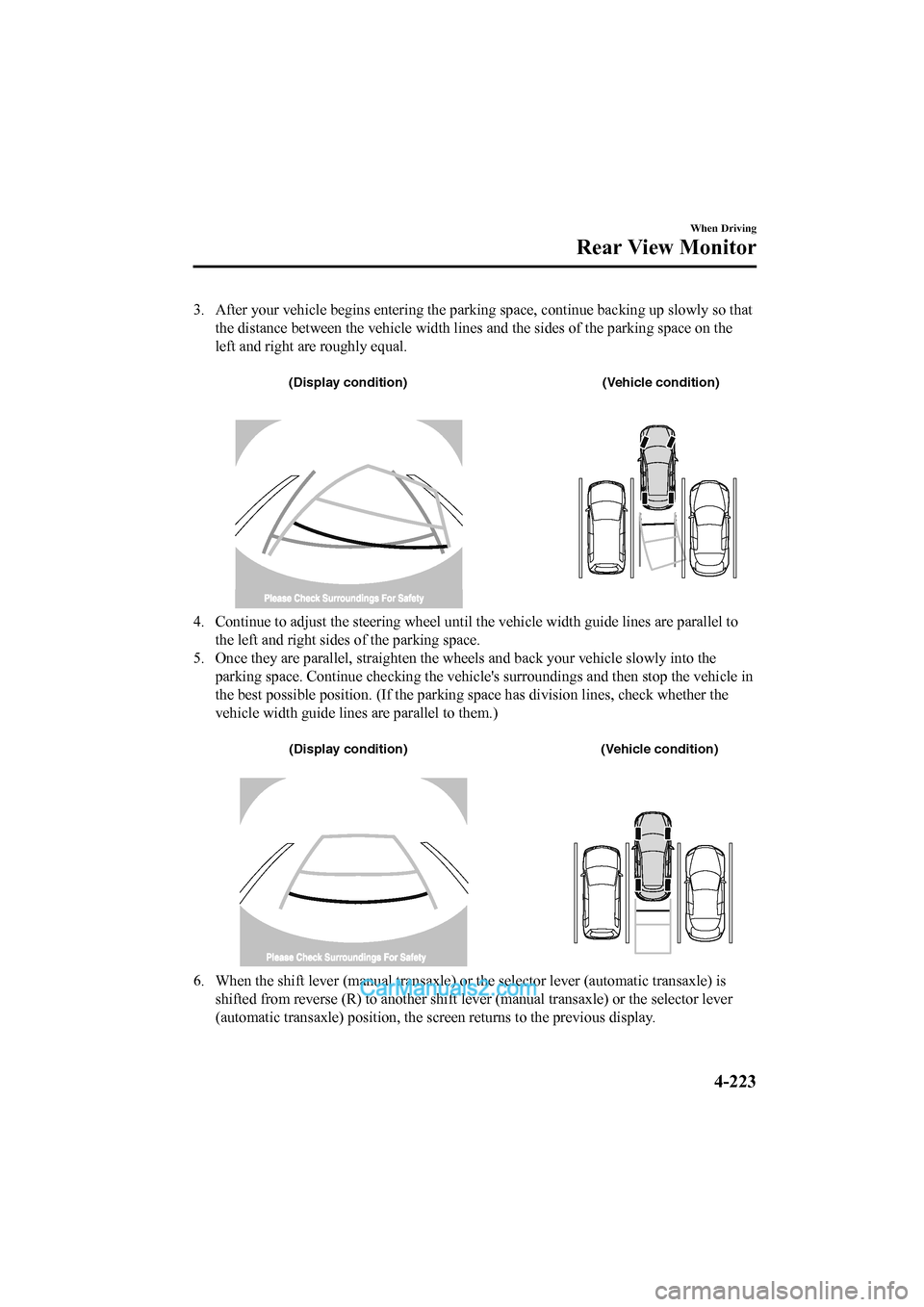
3. After your vehicle begins entering the parking space, continue backing up slowly so that
the distance between the vehicle width lines and the sides of t he parking space on the
left and right are roughly equal.
(Display condition) (Vehicle condition)
4. Continue to adjust the steering wheel until the vehicle width guide lines are parallel to
the left and right sides of the parking space.
5. Once they are parallel, straighten the wheels and back your v ehicle slowly into the
parking space. Continue checkin g the vehicle's surroundings and then stop the vehicle in
the best possible position. (If the parking space has division lines, check whether the
vehicle width guide lines are parallel to them.)
(Display condition) (Vehicle condition)
6. When the shift lever (manual transaxle) or the selector lever (automatic transaxle) is
shifted from reverse (R) to anot her shift lever (manual transaxle) or the selector lever
(automatic transaxle) position, the screen returns to the previ ous display.
When Driving
Rear View Monitor
4-223
2017-6-7 7:51:19 Form No. CX-5 8FY4-EE-17E+L_Edition2
Page 383 of 772
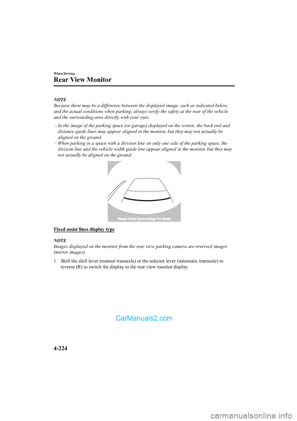
NOTE
Because there may be a difference between the displayed image, such as indicated below,
and the actual conditions when parking, always verify the safety at the rear of the vehicle
and the surrounding area directly with your eyes.
•In the image of the parking space (or garage) displayed on the screen, the back end and
distance guide lines may appear aligned in the monitor, but they may not actually be
aligned on the ground.
•When parking in a space with a division line on only one side of the parking space, the
division line and the vehicle width guide line appear aligned in the monitor, but they may
not actually be aligned on the ground.
Fixed assist lines display type
NOTE
Images displayed on the monitor from the rear view parking camera are reversed images
(mirror images).
1. Shift the shift lever (manual transaxle) or the selector leve r (automatic transaxle) to
reverse (R) to switch the displa y to the rear view monitor display.
When Driving
Rear View Monitor
4-224
2017-6-7 7:51:19 Form No. CX-5 8FY4-EE-17E+L_Edition2
Page 384 of 772
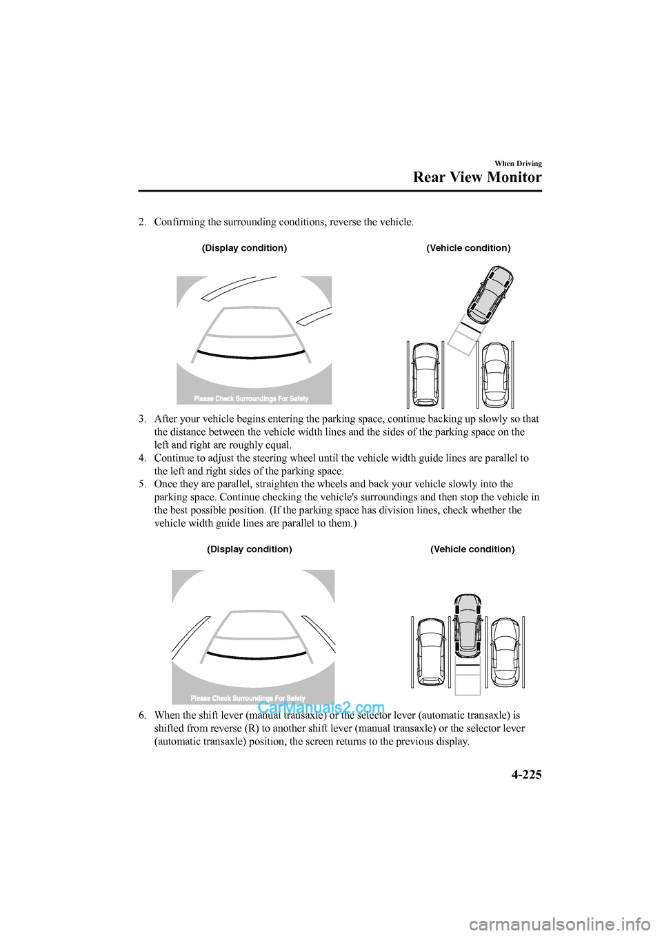
2. Confirming the surrounding conditions, reverse the vehicle.
(Display condition) (Vehicle condition)
3. After your vehicle begins entering the parking space, continu e backing up slowly so that
the distance between the vehicle width lines and the sides of t he parking space on the
left and right are roughly equal.
4. Continue to adjust the steering wheel until the vehicle width guide lines are parallel to
the left and right sides of the parking space.
5. Once they are parallel, straighten the wheels and back your v ehicle slowly into the
parking space. Continue checkin g the vehicle's surroundings and then stop the vehicle in
the best possible position. (If the parking space has division lines, check whether the
vehicle width guide lines are parallel to them.)
(Display condition) (Vehicle condition)
6. When the shift lever (manual transaxle) or the selector lever (automatic transaxle) is
shifted from reverse (R) to anot her shift lever (manual transaxle) or the selector lever
(automatic transaxle) position, the screen returns to the previ ous display.
When Driving
Rear View Monitor
4-225
2017-6-7 7:51:19 Form No. CX-5 8FY4-EE-17E+L_Edition2
Page 385 of 772
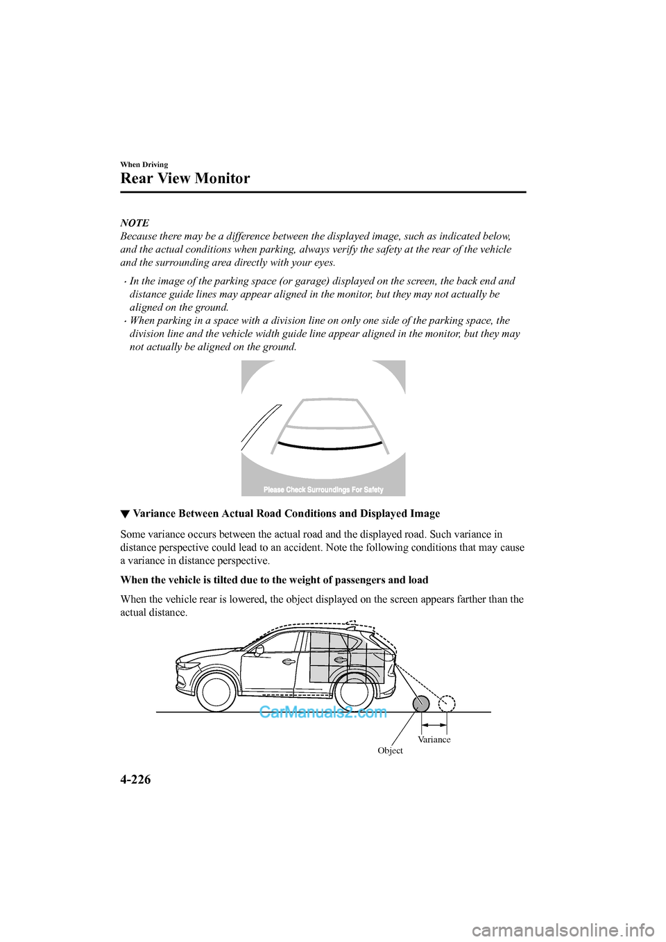
NOTE
Because there may be a difference between the displayed image, such as indicated below,
and the actual conditions when parking, always verify the safety at the rear of the vehicle
and the surrounding area directly with your eyes.
•In the image of the parking space (or garage) displayed on the screen, the back end and
distance guide lines may appear aligned in the monitor, but they may not actually be
aligned on the ground.
•When parking in a space with a division line on only one side of the parking space, the
division line and the vehicle width guide line appear aligned in the monitor, but they may
not actually be aligned on the ground.
▼Variance Between Actual Road C onditions and Displayed Image
Some variance occurs between the actual road and the displayed road. Such variance in
distance perspective could lead to an accident. Note the follow ing conditions that may cause
a variance in distance perspective.
When the vehicle is tilted due to the weight of passengers and load
When the vehicle rear is lowered, the object displayed on the screen appears farther than the
actual distance.
Variance
Object
When Driving
Rear View Monitor
4-226
2017-6-7 7:51:19Form No. CX-5 8FY4-EE-17E+L_Edition2
Page 386 of 772
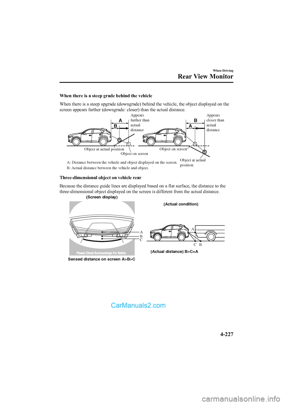
When there is a steep grade behind the vehicle
When there is a steep upgrade (downgrade) behind the vehicle, t he object displayed on the
screen appears farther (downgrade: closer) than the actual dist ance.
A
AB
B
Appears
farther than
actual
distance
Object at actual
position
Object at actual position
Object on screen
A: Distance between the vehicle and object displayed on the screen.
B: Actual distance between the vehicle and object. Object on screenAppears
closer than
actual
distance
Three-dimensional ob
ject on vehicle rear
Because the distance guide lines are displayed based on a flat surface, the distance to the
three-dimensional object displayed on the screen is different f rom the actual distance.
A
A
C B
CB
(Actual distance) B>C=A
Sensed distance on screen A>B>C (Screen display)
(Actual condition)
When Driving
Rear View Monitor
4-227
2017-6-7 7:51:19 Form No. CX-5 8FY4-EE-17E+L_Edition2
Page 387 of 772
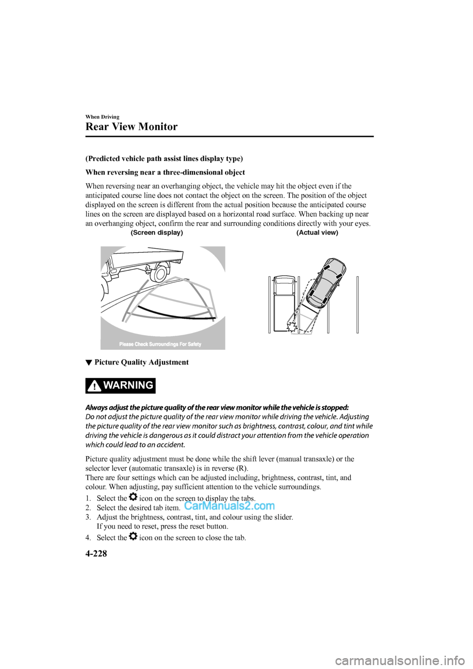
(Predicted vehicle path assist lines display type)
When reversing near a thr ee-dimensional object
When reversing near an overhanging object, the vehicle may hit the object even if the
anticipated course line does not c ontact the object on the screen. The position of the object
displayed on the screen is different from the actual position b ecause the anticipated course
lines on the screen are displayed based on a horizontal road surface. When backing up near
an overhanging object, confirm the rear and surrounding conditi ons directly with your eyes.
(Screen display)(Actual view)
▼Picture Quality Adjustment
WA R N I N G
Always adjust the picture quality of the rear view monitor while the vehicle is stopped:
Do not adjust the picture quality of the rear vi
ew monitor while driving the vehicle. Adjusting
the picture quality of the rear view monitor such as brightness, contrast, colour, and tint while
driving the vehicle is dangerous as it could di stract your attention from the vehicle operation
which could lead to an accident.
Picture quality adjustment must b e done while the shift lever (manual transaxle) or the
selector lever (automatic transaxle) is in reverse (R).
There are four settings which can be adjusted including, bright ness, contrast, tint, and
colour. When adjusting, pay sufficient attention to the vehicle surroundings.
1. Select the
icon on the screen to display the tabs.
2. Select the desired tab item.
3. Adjust the brightness, contrast, tint, and colour using the s lider.
If you need to reset, p ress the reset button.
4. Select the
icon on the screen to close the tab.
When Driving
Rear View Monitor
4-228
2017-6-7 7:51:19 Form No. CX-5 8FY4-EE-17E+L_Edition2
Page 388 of 772
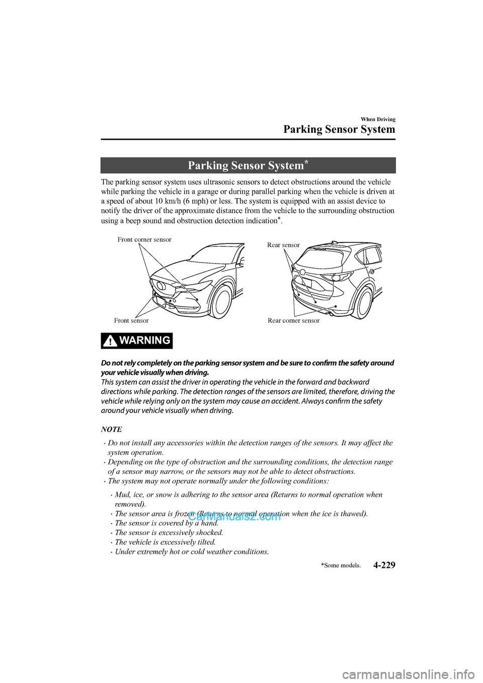
Parking Sensor System*
The parking sensor system uses ultrasonic sensors to detect obstructions around the vehicle
while parking the vehicle in a garage or during parallel parkin g when the vehicle is driven at
a speed of about 10 km/h (6 mph) or less. The system is equippe d with an assist device to
notify the driver of the approximate distance from the vehicle to the surrounding obstruction
using a beep sound and obstruction detection indication
*.
Rear corner sensor
Front corner sensor
Rear sensor
Front sensor
WA R N I N G
Do not rely completely on the parking sensor system and be sure to confirm the safety around
your vehicle visually when driving.
This system can assist the driver in operat ing the vehicle in the forward and backward
directions while parking. The detection ranges of the sensors are limited, therefore, driving the
vehicle while relying only on the system may cause an accident. Always confirm the safety
around your vehicle visually when driving.
NOTE
•Do not install any accessories within the detection ranges of the sensors. It may affect the
system operation.
•Depending on the type of obstruction and the surrounding conditions, the detection range
of a sensor may narrow, or the sensors may not be able to detect obstructions.
•The system may not operate normally under the following conditions:
•Mud, ice, or snow is adhering to the sensor area (Returns to normal operation when
removed).
•The sensor area is frozen (Returns to normal operation when the ice is thawed).
•The sensor is covered by a hand.
•The sensor is excessively shocked.
•The vehicle is excessively tilted.
•Under extremely hot or cold weather conditions.
When Driving
Parking Sensor System
*Some models.4-229
2017-6-7 7:51:19 Form No. CX-5 8FY4-EE-17E+L_Edition2
Page 389 of 772

•The vehicle is driven on bumps, inclines, gravel, or grass covered roads.
•Anything which generates ultrasound is near the vehicle, such as another vehicle's
horn, the engine sound of a motorcycle, the air brake sound of a large-sized vehicle, or
another vehicle's sensors.
•The vehicle is driven in heavy rain or in road conditions causing water-splash.
•A commercially-available wing pole or an aerial for a radio transmitter is installed to
the vehicle.
•The vehicle is moving towards a tall or square curbstone.
•An obstruction is too close to the sensor.
•Obstructions under the bumper may not be detected. Obstructions that are lower than the
bumper or thin which may have been initially detected but are no longer detected as the
vehicle approaches more closely.
•The following types of obstructions may not be detected:
•Thin objects such as wire or rope
•Things which absorb sonic waves easily such as cotton or snow
•Angular shaped objects
•Very tall objects, and those which are wide at the top
•Small, short objects
•Always have the system inspected at an expert repairer, we recommend an Authorised
Mazda Repairer if any shock is applied to the bumpers, even in a minor accident. If the
sensors are deviated, they cannot detect obstructions.
•The system may have a malfunction if the b eep does not operate or the indicator light
does not illuminate when the park assist sensors switch is turned on. Consult an expert
repairer, we recommend an Authorised Mazda Repairer.
•The system may have a malfunction if the beep sound which indicates a system
malfunction is heard and the indicator light flashes. Consult an expert repairer, we
recommend an Authorised Mazda Repairer.
•The beeper which indicates a system malfunction may not be heard if the ambient
temperature is extremely cold, or mud, ice, or snow adheres to the sensor area. Remove
any foreign material from the sensor area.
•When installing a trailer hitch, consult an expert repairer, we recommend an Authorised
Mazda Repairer.
When Driving
Parking Sensor System
4-230
2017-6-7 7:51:19 Form No. CX-5 8FY4-EE-17E+L_Edition2
Page 390 of 772
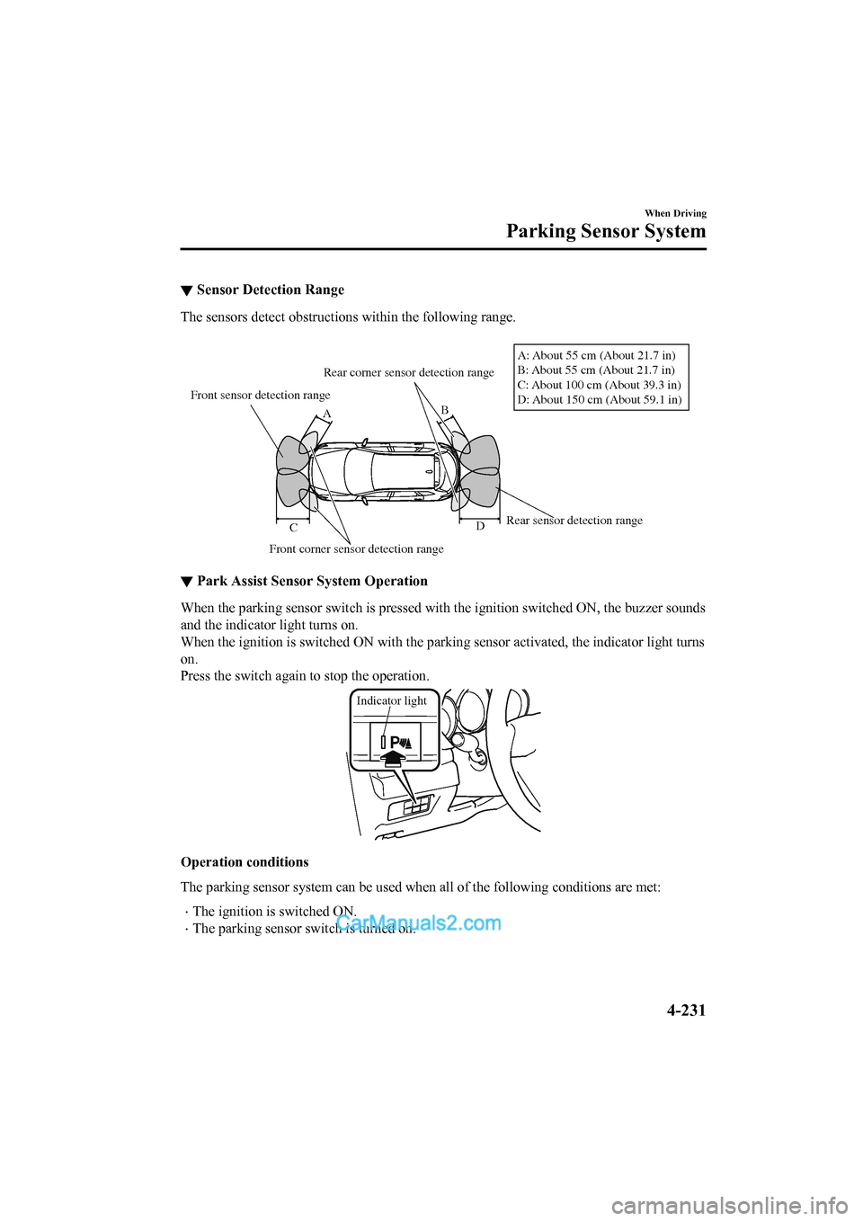
▼Sensor Detection Range
The sensors detect obstructions within the following range.
Front sensor detection range
Front corner sensor detection range Rear sensor detection range
Rear corner sensor detection range
B
A
D
C A: About 55 cm (About 21.7 in)
B: About 55 cm (About 21.7 in)
C: About 100 cm (About 39.3 in)
D: About 150 cm (About 59.1 in)
▼
Park Assist Sensor
System Operation
When the parking sensor switch is pressed with the ignition switched ON, the buzzer sounds
and the indicator light turns on.
When the ignition is switched ON with the parking sensor activa ted, the indicator light turns
on.
Press the switch again to stop the operation.
Indicator light
Operation conditions
The parking sensor system can be used when all of the following conditions are met:
•The ignition is switched ON.
•The parking sensor switch is turned on.
When Driving
Parking Sensor System
4-231
2017-6-7 7:51:19 Form No. CX-5 8FY4-EE-17E+L_Edition2