oil MAZDA MX-5 1994 Workshop Manual
[x] Cancel search | Manufacturer: MAZDA, Model Year: 1994, Model line: MX-5, Model: MAZDA MX-5 1994Pages: 1708, PDF Size: 82.34 MB
Page 437 of 1708

K AUTOMATIC TRANSMISSION FLUID (ATF) Fluid leaks Check for fluid leaks of the transmission as shown below, and repair or replace as necessary. 1. Gaskets, O-ring, and plugs 2. Oil hoses, oil pipes, and connections 3. Oil cooler @ .... O-RING @ .... GASKET 0 .... OIL SEAL 0 .... PLUG @ .... OTHER Gartner Banana
Page 438 of 1708

AUTOMATIC TRANSMISSION FLUID (ATF) K REPLACEMENT 1. On level ground, jack up the vehicle and support it evenly on safety stands. Warning When the transmission and the ATF are hot, they can cause burns to the skin. Allow the transmis- sion and the ATF to cool before doing this proce- dure. 2. Loosen the oil pan installation bolts, and drain the ATF into a container. 3. Remove the oil pan and gasket. 4. Clean the oil pan and the magnet. 5. Install the oil pan along with a new gasket. Tightening torque: 5.9-7.8 N-m (60-80 kgfecm, 53-69 in-lbf) 6. Add approximately 4.0 L (4.2 US qt, 3.5 Imp qt} ATF, and check the ATF level. (Refer to page K-35.) Specified ATF: DexronmII or M-I11 Gartner Banana
Page 447 of 1708

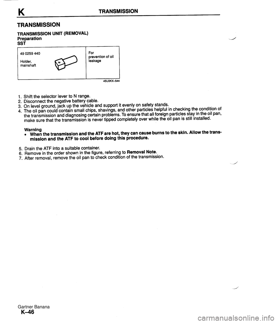
TRANSMISSION TRANSMISSION UNIT (REMOVAL) Preparation SST 49 0259 440 Holder, mainshaft For prevention of oil leakage 1. Shift the selector lever to N range. 2. Disconnect the negative battery cable. 3. On level ground, jack up the vehicle and support it evenly on safety stands. 4. The oil pan could contain small chips, shavings, and other particles helpful in checking the condition of the transmission and diagnosing certain problems. To ensure that all foreign particles stay in the oil pan, make sure that the transmission is never tipped completely over while the oil pan is still installed. Warning When the transmission and the ATF are hot, they can cause burns to the skin. Allow the trans- mission and the ATF to cool before doing this procedure. 5. Drain the ATF into a suitable container. 6. Remove in the order shown in the figure, referring to Removal Note. 7. After removal, remove the oil pan to check condition of the transmission. Gartner Banana
Page 448 of 1708

TRANSMISSION K 1. Shift rod 12. Lockup solenoid connector 2. Undercover 13. Oil pipe 3. Performance rod 14. Harness 4. Exhaust pipe 15. Power plant frame (PPF) 5. Propeller shaft Removal Note ............. page K-48 Removal .................... section L 1 6. Undercover 6. Speedometer cable 17. Torque converter Nut - 7. Vacuum hose 18. Starter u 8. Parklneutral switch connector 19. Transmission mount bolt 9. Vehicle speed pulse generator connector 20. Transmission 10. Solenoid connector Removal Note ............. page K-49 11. ATF thermosensor connector Gartner Banana
Page 451 of 1708

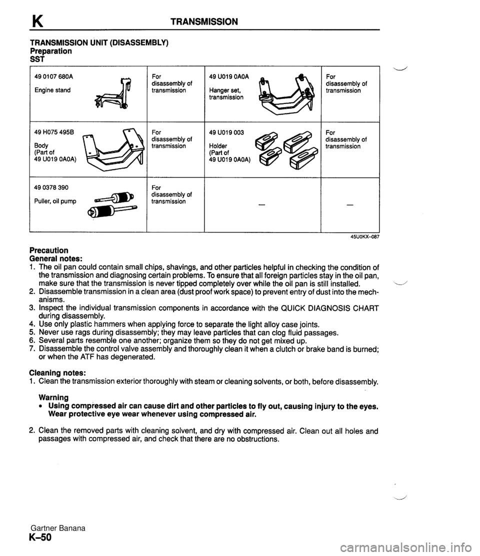
TRANSMISSION TRANSMISSION UNIT (DISASSEMBLY) Preparation SST 49 H075 4958 Body (Part of 49 U019 OAOA) For disassembly of transmission For disassembly of transmission For disassembly of transmission 49 U019 OAOA Hanger set, transmission 49 U019 003 Holder (Part of 49 U019 OAOA) For disassembly of transmission For disassembly of transmission Precaution General notes: 1. The oil pan could contain small chips, shavings, and other particles helpful in checking the condition of the transmission and diagnosing certain problems. To ensure that all foreign particles stay in the oil pan, make sure that the transmission is never tipped completely over while the oil pan is still installed. L/ 2. Disassemble transmission in a clean area (dust proof work space) to prevent entry of dust into the mech- anisms. 3. Inspect the individual transmission components in accordance with the QUICK DIAGNOSIS CHART during disassembly. 4. Use only plastic hammers when applying force to separate the light alloy case joints. 5. Never use rags during disassembly; they may leave particles that can clog fluid passages. 6. Several parts resemble one another; organize them so they do not get mixed up. 7. Disassemble the control valve assembly and thoroughly clean it when a clutch or brake band is burned; or when the ATF has degenerated. Cleaning notes: 1. Clean the transmission exterior thoroughly with steam or cleaning solvents, or both, before disassembly. Warning Using compressed air can cause dirt and other particles to fly out, causing injury to the eyes. Wear protective eye wear whenever using compressed air. 2. Clean the removed parts with cleaning solvent, and dry with compressed air. Clean out all holes and passages with compressed air, and check that there are no obstructions. Gartner Banana
Page 452 of 1708

TRANSMISSION K Components / @ O-RING. O-RING, REPLACE O-RING, REPLACE 1. Vacuum diaphragm 6. Oil pan On-vehicle Removal ....... page K-130 7. Magnet Inspection ................ page K-130 8. Control valve body On-vehicle Installation ..... page K-131 Disassembly I Inspection ... page K-112 On-vehicle Adjustment ..... page K-131 Assembly ................ page K-125 2. Lockup control solenoid valve On-vehicle Removal ....... page K-128 Inspection ................ page K- 42 On-vehicle Installation ..... page K-129 3. Vehicle speed pulse generator 9. Solenoid valve connector Inspection ................ page K- 41 10. Converter housing 4. ParWneutral switch 11. 2nd band servo w Inspection ................ page K- 39 Disassembly I Inspection I Adjustment ............... page K- 40 Assembly ............... page K- 83 5. Torque converter On-vehicle Adjustment ..... page K- 85 Inspection ................ page K- 61 Gartner Banana
Page 453 of 1708

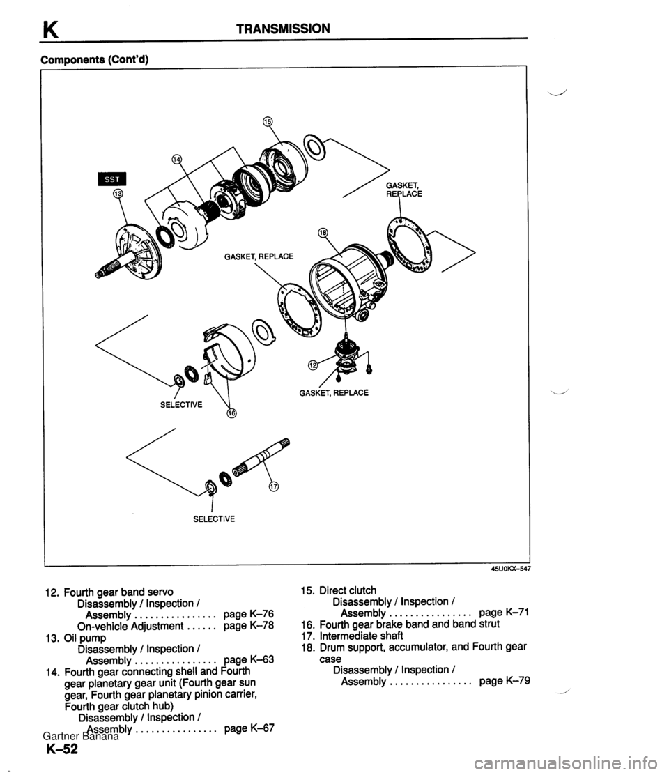
K TRANSMISSION Components (Cont'd) 4 GASKET, REPLACE SELECTIVE %I 12. Fourth gear band servo Disassembly / Inspection / ................ Assembly page K-76 ...... On-vehicle Adjustment page K-78 13. Oil pump Disassembly / Inspection 1 ................ Assembly page K-63 14. Fourth gear connecting shell and Fourth gear planetary gear unit (Fourth gear sun gear, Fourth gear planetary pinion carrier, Fourth gear clutch hub) Disassembly / Inspection / ................ Assembly page K-67 15. Direct clutch Disassembly / Inspection / ................ Assembly page K-71 16. Fourth gear brake band and band strut 17. Intermediate shaft 18. Drum support, accumulator, and Fourth gear case Disassembly / Inspection / ................ Assembly page K-79 Gartner Banana
Page 455 of 1708

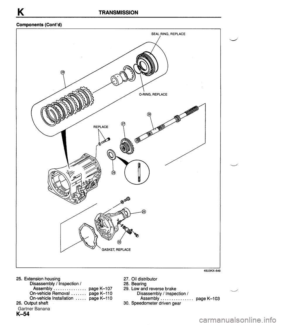
K TRANSMISSION Components (Cont'd) SEAL RING, REPLACE / O-RING, REPLACE /' $,&" $ GASKET, REPLACE 25. Extension housing 27. Oil distributor Disassembly I Inspection I 28. Bearing Assembly ............... page K-107 29. Low and reverse brake On-vehicle Removal ....... page K-110 Disassembly I Inspection / On-vehicle Installation ..... page K-110 Assembly .............. 26. Output shaft 30. Speedometer driven gear page K-103 Gartner Banana
Page 456 of 1708

TRANSMISSION K Procedure 1. Place wooden blocks under the transmission at the con- verter housing and the extension housing positions. 2. Remove the oil pan and gasket. Examine any material found in the pan or on the magnet to determine the condition of the transmission. Clutch facing material . . . . . Drive plate and brake band wear Steel (magnetic) . . . . . . . . . . Bearing, gear, and driven plate wear Aluminum (nonmagnetic) . . Bushings or cast alumi- num parts wear If large amounts of material are found, replace the torque converter and carefully check the transmission for the cause. 3. Install the oil pan and gasket with a few bolts to protect the valve body. 4. Remove the vacuum diaphragm, lockup control solenoid valve, vehicle speed pulse generator, and O-rings. 5. Remove the parwneutral switch. 6. Remove the speedometer driven gear from the exten- sion housing. 7. Remove the O-ring from the speedometer driven gear. Gartner Banana
Page 457 of 1708

K TRANSMISSION 8. Remove the torque converter, and immediately turn it so that the hole faces upward. This will help to keep any re- maining fluid from spilling. 9. Assemble the SST as shown. 10. Mount the transmission onto the SST. 11. Remove the oil pan and gasket. 12. Remove the magnets. 13. Disconnect the solenoid valve connectors. 14. Remove the harnesses from the bracket. Gartner Banana