oil MAZDA MX-5 1994 Workshop Manual
[x] Cancel search | Manufacturer: MAZDA, Model Year: 1994, Model line: MX-5, Model: MAZDA MX-5 1994Pages: 1708, PDF Size: 82.34 MB
Page 310 of 1708

OUTLINE OUTLINE SPECIFICATIONS (i.e. powertrain control module (engine), audio, etc.) *2 With System Selector (49 B019 9AO) test switch at SELF TEST. - Engine Item Starter Ignition system Cylinder Arrangement Battery BP DOHC MT I AT 12, Negative ground S46A24L(S) (32 Ah) Maintenance-free 20.0 A.C. I REAR Voltage V Type and capacity (5-hour rate) 12-65 -. 1 2-70 Drive belt deflection mm {in} Dark current" m A Transistorized (built-in voltage regulator) 14.3-1 4.9 21.5 I0.846) 8 (0.31 1 Ignition timing** BTDC ("CA)lrpm U Alternator 'I Dark current is the constant flow of current while the ignition switch is OFF. 45UoGX-003 New Used 101850 Ignition coil Spark plug FRONT 55-7.0 (0.22-0.27) 6.0-7.5 (0.2H.29) 101800 TY pe Primary coil winding n Secondary coil winding kR Type Plug gap mm {in) Firing order Type Output V-A Regulator type Regulated voltage V TY pe Output V-kW Molded (with igniter) - 8.7-1 2.9 (20°C (68°F)) NGK : BKR5E-11 BKR6E-11 (Standard ... MT) NIPPONDENSO : K16PR-U11 K20PR-U11 (Standard ... MT, AT) 1 .O-1.1 IO.040-0.043) 1-3-4--2 Brush length mm {in) Direct 124.95 17.0 i0.67) 11.5 I0.45) Brush length mm {in} Standard Minimum Coaxial reduction 12-1.4 17.5 i0.69) 12.0 i0.47) Standard Minimum Electronic spark advance (ESA) Powertrain control module (engine) controls spark advance Type Spark advance control Gartner Banana
Page 319 of 1708
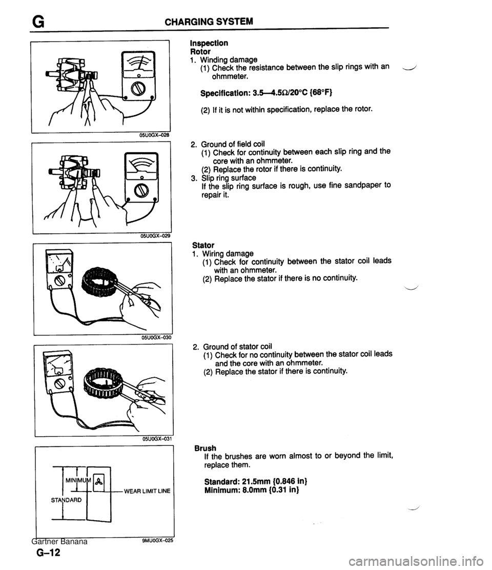
G CHARGING SYSTEM WEAR LIMIT LINE Inspection Rotor 1. Winding damage (1) Check the resistance between the slip rings with an J ohmmeter. Specification: 3.5--4.5SU20°C (68°F) (2) If it is not within specification, replace the rotor. 2. Ground of field coil (1) Check for continuity between each slip ring and the core with an ohmmeter. (2) Replace the rotor if there is continuity. 3. Slip ring surface If the slip ring surface is rough, use fine sandpaper to repair it. Stator 1. Wiring damage (1) Check for continuity between the stator coil leads with an ohmmeter. (2) Replace the stator if there is no continuity. 2. Ground of stator coil (1)~heck for no continuity between the stator coil leads and the core with an ohmmeter. (2) Replace the stator if there is continuity. Brush If the brushes are worn almost to or beyond the limit, replace them. Standard: 21.5mm (0.846 in) Minimum: 8.0mm (0.31 in) Gartner Banana
Page 321 of 1708
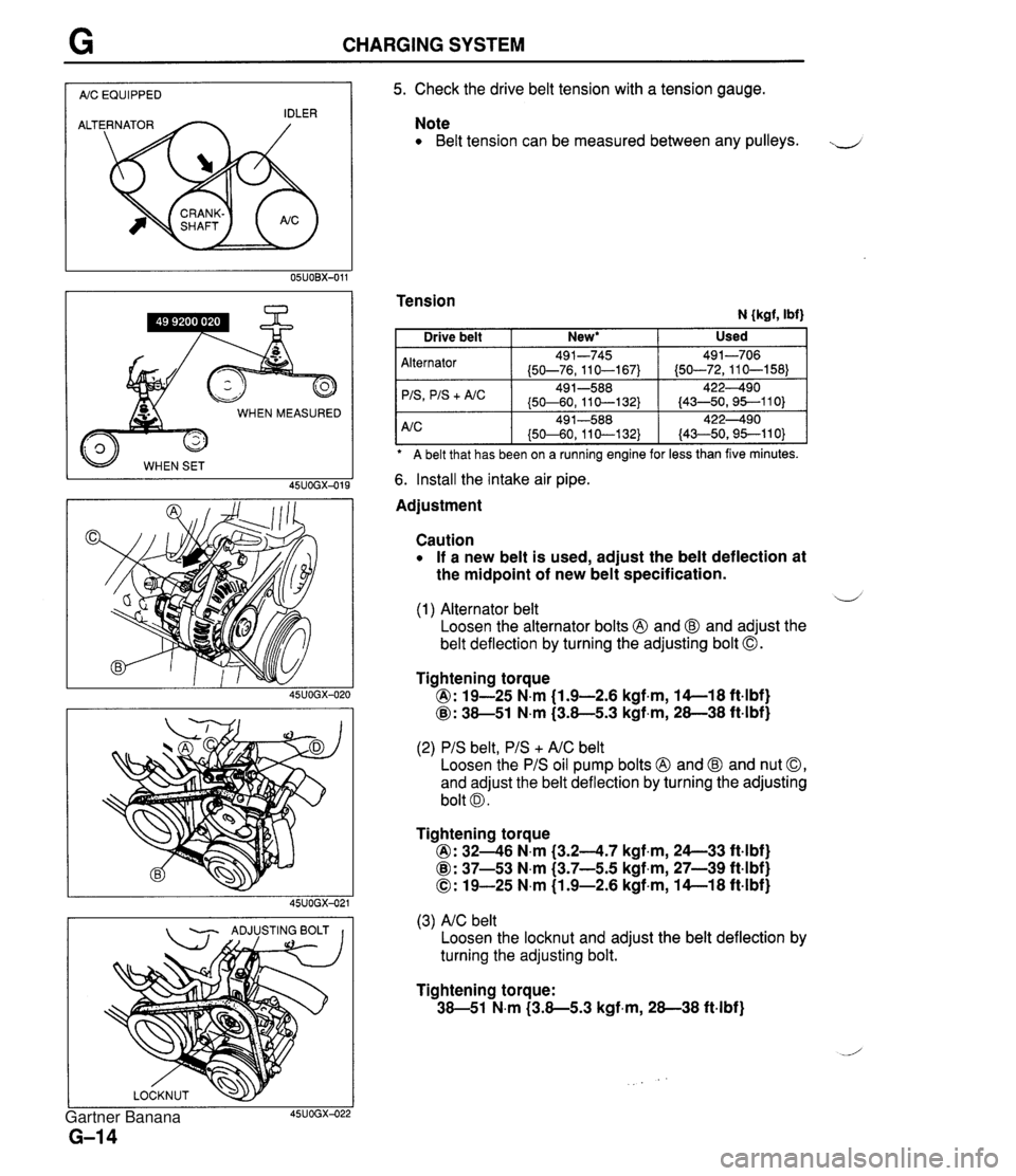
CHARGING SYSTEM I AIC EQUIPPED I WHEN MEASURED 45UOGX-015 - ADJUSTING BOLT I I 5. Check the drive belt tension with a tension gauge. Note Belt tension can be measured between any pulleys. J Tension N {kgf, Ibf) A belt that has been on a ruining engine for less than five minutes. Alternator 'IS
+ A/C 6. Install the intake air pipe. Used Drive belt Adjustment New* I Caution If a new belt is used, adjust the belt deflection at the midpoint of new belt specification. 491-745 (50-76,110-167) 49 1-588 (50-60, 11 0-1 32) d (1) Alternator belt Loosen the alternator bolts @ and @ and adjust the belt deflection by turning the adjusting bolt 0. 491-706 (50-72,110-158) 422490 (43-50,95--110) Tightening torque @: 19-25 N.m (1.9-2.6 kgf.m, 14-1 8 ft4bf) @: 38-51 N.m (3.8-5.3 kgf,m, 28-38 ft-lbf) (2) PIS belt, PIS + AIC belt Loosen the PIS oil pump bolts @ and @ and nut 0, and adjust the belt deflection by turning the adjusting bolt 0. Tightening torque @: 3246 N.m (3.24.7 kgf.m, 24--33 ft4bf) @: 37-53 N.m (3.7-5.5 kgf,m, 27-39 ft-lbf) 0: 19-25 N.m (1.9-2.6 kgf-m, 14-1 8 ft-lbf) (3) AIC belt Loosen the locknut and adjust the belt deflection by turning the adjusting bolt. Tightening torque: 38-51 N.m (3.8-5.3 kgf-m, 28-38 ft-lbf) Gartner Banana
Page 322 of 1708
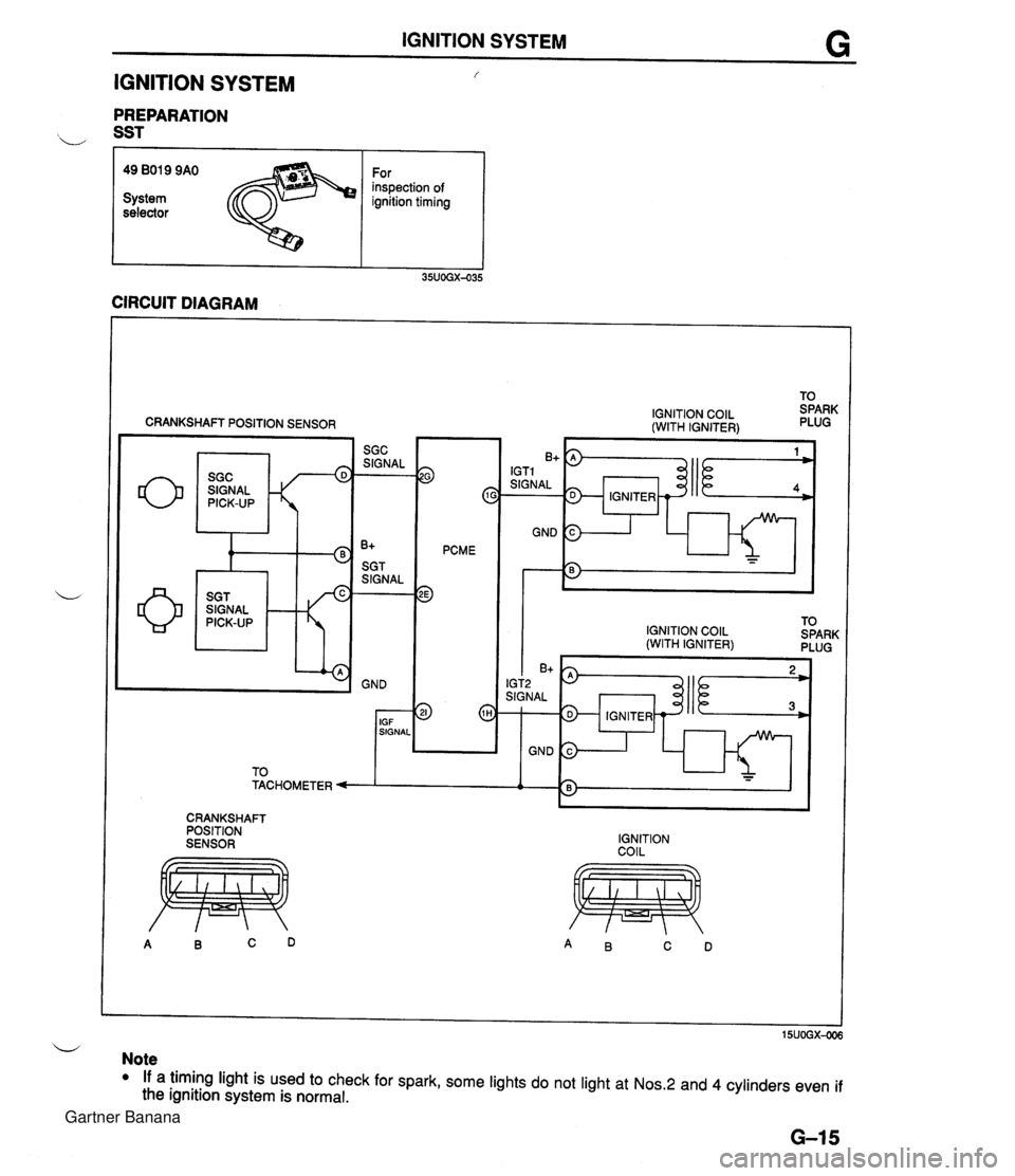
IGNITION SYSTEM G IGNITION SYSTEM f PREPARATION b SST r I I 49 BO19 9AO For inspection of System ignition timing selector CIRCUIT DIAGRAM CRANKSHAFT POSITION SENSOR SIGNAL w 9 c PCME 3 IGNITION COlL (WITH IGNITER) IGNITION COlL TO (WITH IGNITER) SPARK PLUG I I I 6'5) IGT2 SIGNAL 1 IGNITER - GND 3 1 h - - CRANKSHAFT POSITION SENSOR IGNITION COIL u Note If a timing light is used to check for spark, some lights do not light at Nos.2 and 4 cylinders even if the ignition system is normal. Gartner Banana
Page 323 of 1708
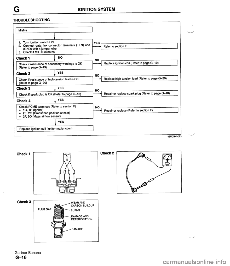
IGNITION SYSTEM TROUBLESHOOTING Misfire I 1 Check 1 NO NO 1. Turn ignition switch ON 2. Connect data link connector terminals (TEN) and (GND) with a jumper wire 3. Check if MIL illuminates I Check if resistance of secondary windings is OK Replace ignition coil (Refer to page G-19) (Refer to page G-19) I Refer to section F Check 2 Check if resistance of Replace high-tension lead (Refer to page G-20) (Refer to page G-20) I I Check 3 Check if spark plug is OK ( I Check 4 1 YES I Check PCME terminals (Refer to section F) a 1 G, 1 H (Igniter) 0 2E, 2G (Crankshaft position sensor) Repair or replace (Refer to section F) ( 2F, 20 ass airflow sensor) YES Replace ignition coil (igniter malfunction) 1 Check 1 Check 3 Check 2 PLUG WEAR AND CARBON BUILDUP BURNS DAMAGE AND DETERIORATION DAMAGE Gartner Banana
Page 324 of 1708
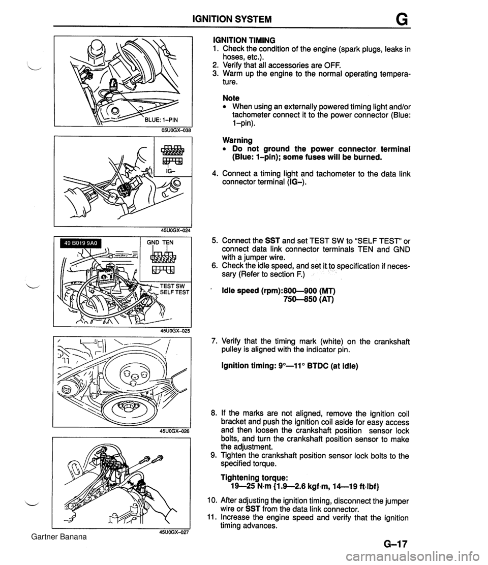
IGNITION SYSTEM G GND TEN I I I IGNITION TIMING 1. Check the condition of the engine (spark plugs, leaks in hoses, etc.). 2. Verify that all accessories are OFF. 3. Warm up the engine to the normal operating tempera- ture. Note When using an externally powered timing light and/or tachometer connect it to the power connector (Blue: l-pin). Warning Do not ground the power connector. terminal (Blue: l-pin); some fuses will be burned. 4. Connect a timing light and tachometer to the data link connector terminal (IG-). 5. Connect the SST and set TEST SW to "SELF TEST" or connect data link connector terminals TEN and GND with a jumper wire. 6. Check the idle speed, and set it to specification if neces- sary (Refer to section F.) ' Idle speed (rpm):800-900 (MT) 75-50 (AT) 7. Verify that the timing mark (white) on the crankshaft pulley is aligned with the indicator pin. Ignition timing: 9"-11" BTDC (at idle) 8. If the marks are not aligned, remove the ignition coil bracket and push the ignition coil aside for easy access and then loosen the crankshaft position sensor lock bolts, and turn the crankshaft position sensor to make the adjustment. 9. Tighten the crankshaft position sensor lock bolts to the specified torque. Tightening torque: 19-25 N-m (1 3-2.6 kgf~m, l4--19 ft.lbf) 10. After adjusting the ignition timing, disconnect the jumper wire or SST from the data link connector. 11. Increase the engine speed and verify that the ignition timing advances. Gartner Banana
Page 326 of 1708
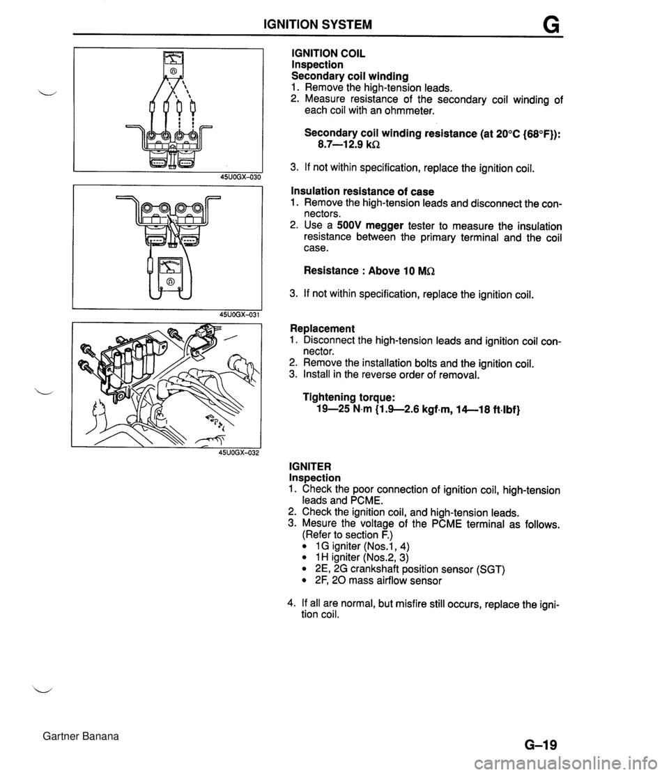
IGNITION SYSTEM IGNITION COIL lnspection Secondary coil winding 1. Remove the high-tension leads. u 2. Measure resistance of the secondary coil winding of each coil with an ohmmeter. Secondary coil winding resistance (at 20°C (68°F)): 8.7-1 2.9 kR 3. If not within specification, replace the ignition coil. 45UOGX-030 I I Insulation resistance of case 1. Remove the high-tension leads and disconnect the con- nectors. 2. Use a 500V megger tester to measure the insulation resistance between the primary terminal and the coil case. Resistance : Above 10 MR 3. If not within specification, replace the ignition coil. L I 45UOGX-031 Replacement 1. Disconnect the high-tension leads and ignition coil con- nector. 2. Remove the installation bolts and the ignition coil. 3. Install in the reverse order of removal. L Tightening torque: 19-25 N.m (1.9--2.6 kgf-m, 14--18 ft-lbf) 45UOGX-032 IGNITER Inspection 1. Check the poor connection of ignition coil, high-tension leads and PCME. 2. Check the ignition coil, and high-tension leads. 3. Mesure the voltage of the PCME terminal as follows. (Refer to section F.) 1 G igniter (Nos.1, 4) 1 H igniter (Nos.2, 3) 2E, 2G crankshaft position sensor (SGT) 2F, 20 mass airflow sensor 4. If all are normal, but misfire still occurs, replace the igni- tion coil. Gartner Banana
Page 333 of 1708
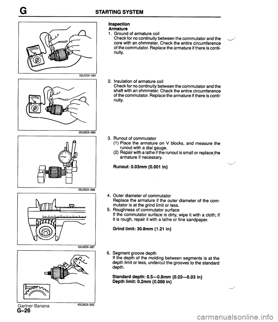
STARTING SYSTEM Inspection Armature 1. Ground of armature coil Check for no continuity between the commutator and the .J core with an ohmmeter. Check the entire circumference of the commutator. Replace the armature if there is conti- nuity. 2, Insulation of armature coil Check for no continuity between the commutator and the shaft with an ohmmeter. Check the entire circumference of the commutator. Replace the armature if there is conti- nuity. 3. Runout of commutator (1) Place the armature on V blocks, and measure the runout with a dial gauge. (2) Repair with a lathe if the runout is small or replace,the armature if necessary. -1' Runout: 0.03mm (0.001 in) 4. Outer diameter of commutator Replace the armature if the outer diameter of the com- mutator is at the grind limit or less. 5. Roughness of commutator surface If the commutator surface is dirty, wipe it with a cloth; if it is rough, repair it with a lathe or fine sandpaper. Grind limit: 30.8mm (1.21 in) 6. Segment groove depth If the depth of the molding between segments is at the depth limit or less, undercut the grooves to the standard depth. Standard depth: 0.5--0.8mm (0.02-4.03 in) Depth limit: 0.2mm (0.008 in) Gartner Banana
Page 334 of 1708
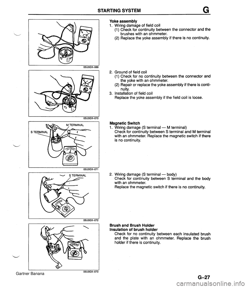
STARTING SYSTEM Yoke assembly 1. Wiring damage of field coil (1) Check for continuity between the connector and the brushes with an ohmmeter. (2) Replace the yoke assembly if there is no continuity. 2. Ground of field coil (1) Check for no continuity between the connector and the yoke with an ohmmeter. (2) Repair or replace the yoke assembly if there is conti- . nuity. 3. Installation of field coil Replace the yoke assembly if the field coil is loose. Magnetic Switch 1. Wiring damage (S terminal - M terminal) Check for continuity between S terminal and M terminal with an ohmmeter. Replace the magnetic switch if there is no continuity. 2. Wiring damage (S terminal - body) Check for continuity between S terminal and the body with an ohmmeter. Replace the magnetic switch if there is no continuity. Brush and Brush Holder Insulation of brush holder Check for no continuity between each insulated brush and the plate with an ohmmeter. Replace the brush holder if there is continuity. Gartner Banana
Page 338 of 1708

OUTLINE, TROUBLESHOOTING GUIDE H OUTLINE SPECIFICATIONS I Clutch control L' Clutch cover Clutch disc Clutch pedal - Enginerrransmission BP DOHC item - M15M-D 1 Master cvlinder inne I Hydraulic Inner diameter mm {in) I 150 (5.91) I Pressure plate side I n n rn cr Tvpe . . Set load N {kgf, Ibf) Outer diameter mm {in) Pedal ratio 6.13 Full stroke mm {in) I 120 (4.72) Diaphraam spring .-.- 4,310 (440,968) 21 5 18.46) . - Height mm {in) * diameter mm {in) TROUBLESHOOTING GUIDE . - I 75--185 i6.89--7.283 15.87 (0.625) . - Release cylinder inner diameter mm {in) Clutch fluid I Problem I Possible Cause 19.05 i0.750) FMVSS116 DOT-3 Clutch disc facing surface hardened or oil on surface Pressure plate damaged u Diaphragm spring damaged or weak lnsufficient clutch pedal play I Slipping I Clutch disc facing worn excessively I Flywheel damaged Faulty disengagement I Clutch disc damaged or excessive runout Clutch disc spines rusted or worn Oil on clutch disc facing Diaphragm spring weak Excessive clutch pedal play Insufficient clutch fluid Leakage of clutch fluid I 1 Clutch disc facing hardened or damaged Clutch vibrates when accelerating I I Clutch disc facing rivets loose Oil on clutch disc facing Torsion dampers weak Clutch pedal stlcks Abnormal noise Pressure plate damaged or excessive runout Flywheel surface hardened or damaged Loose or worn engine mount Pedal shaft not pro~erlv lubricated Clutch release collar damaged Poor lubrication of release collar sleeve Torsion dampers weak Excessive crankshaft end play I I Pilot bearing worn or damaged I I Worn ~ivot points of release fork Action Replace Repair or replace Repair or replace Replace Adjust ~ebair or replace Replace Remove rust or replace Repair or replace Replace Adjust Add fluid Locate and repair or replace Repair or replace Replace Repair or replace Replace Replace Repair or replace Tighten or replace Lubricate or replace Replace Lubricate or replace Replace Repair Replace Repair or replace Page H-14 H-14 H-14 H-14 H-14 H-14 section B H- 6 H-14 H-14 H-14 section B H-14 H-14 45UOHX-OC Gartner Banana