oil MAZDA MX-5 1994 Workshop Manual
[x] Cancel search | Manufacturer: MAZDA, Model Year: 1994, Model line: MX-5, Model: MAZDA MX-5 1994Pages: 1708, PDF Size: 82.34 MB
Page 492 of 1708

TRANSMISSION K REARCLUTCH Preparation SST Preinspection Rear clutch operation 1, Install the rear clutch onto the drum support along with the seal rings. Apply compressed air through the oil pas- sage as shown. i/' Air pressure: 392 kPa {4.0 kg/cm2,57 psi} max. 2. Verify that the retaining plate moves toward the snap ring. If not, the seal ring or O-ring may be damaged or fluid may be leaking at the piston check ball. Inspect them, and replace when assembling. 49 0378 375 Compressor, clutch spring Clearance between retaining plate and snap ring Measure the clearance between the retaining plate and the snap ring. For removal / installation of rear clutch Clearance: 0.8-1.0mm (0.0324.039 in) Adjust the clearance by installing the correct retaining plate. Gartner Banana
Page 494 of 1708
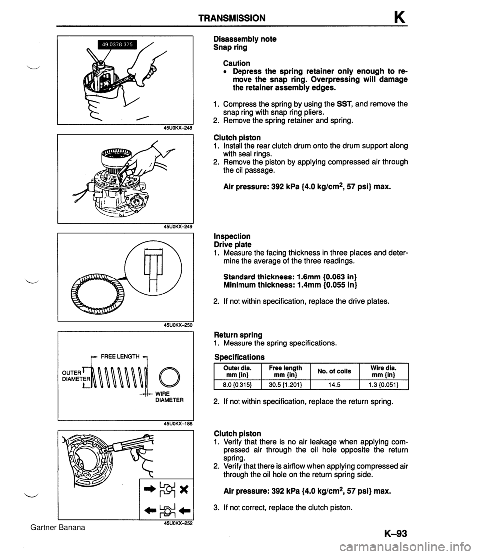
TRANSMISSION K WIRE DIAMETER Disassembly note Snap ring Caution Depress the spring retainer only enough to re- move the snap ring. Overpressing will damage the retainer assembly edges. 1. Compress the spring by using the SST, and remove the snap ring with snap ring pliers. 2. Remove the spring retainer and spring. Clutch piston 1. Install the rear clutch drum onto the drum support along with seal rings. 2. Remove the piston by applying compressed air through the oil passage. Air pressure: 392 kPa (4.0 kg/cm2, 57 psi) max. Inspection Drive plate 1. Measure the facing thickness in three places and deter- mine the average of the three readings. Standard thickness: 1.6mm (0.063 in) Minimum thickness: 1.4mm (0.055 in) 2. If not within specification, replace the drive plates. Return spring 1. Measure the spring specifications. I Outer dia. I Free length I No. of I ;i;;i I mm fin) mm {in} 2. If not within specification, replace the return spring. Clutch piston 1. Verify that there is no air leakage when applying com- pressed air through the oil hole opposite the return spring. 2. Verify that there is airflow when applying compressed air through the oil hole on the return spring side. Air pressure: 392 kPa (4.0 kg/cm2, 57 psi) max. 3. If not correct, replace the clutch piston. Gartner Banana
Page 496 of 1708

TRANSMISSION K 13. Arrange the retaining plate so that the toothless area is in line with the lubrication hole in the rear clutch drum. 14. Install the retaining plate into the rear clutch drum, with the step of the retaining plate facing upward. 15. Install the snap ring. 16. Measure the clearance between the retaining plate and snap ring with a feeler gauge. If not within specification, adjust the clearance by installing the correct retaining plate. Clearance: 0.8-1.0mm (0.032-4.039 in) Retaining plate size mm [in) Caution Applying compressed air to the assembled clutch pack for longer than 3 seconds at a time will dam- age the seal. 17. Install the rear clutch onto the drum support along with the seal rings. Apply compressed air through the oil pas- sage and check the clutch operation. Air pressure: 392 kPa (4.0 kg/cm2, 57 psi) max. 18. Apply petroleum jelly to the bearing, and install it onto the rear clutch drum. Bearing outer diameter: 35.0mm (1.378 in) Gartner Banana
Page 503 of 1708

K TRANSMISSION LOW AND REVERSE BRAKE Preparation SST Preinspection Low and reverse brake operation 1. Apply compressed air through the oil passage as shown. 49 0378 346 Hex head wrench Air pressure: 392 kPa (4.0 kglcm2, 57 psi) max. For removal I installation of one-way clutch 2. Verify that the retaining plate moves toward the snap ring. If not, the seal ring or O-ring may be damaged or fluid may be leaking at the piston check ball. Inspect them, and replace as necessary when assembling. Clearance between retaining plate and snap ring 1. Measure the clearance between the retaining plate and the snap ring. Clearance: 0.8-1.05mm (0.032--0.041 in) i/ 2. Select and install the correct retaining plate when as- sembling. Gartner Banana
Page 505 of 1708
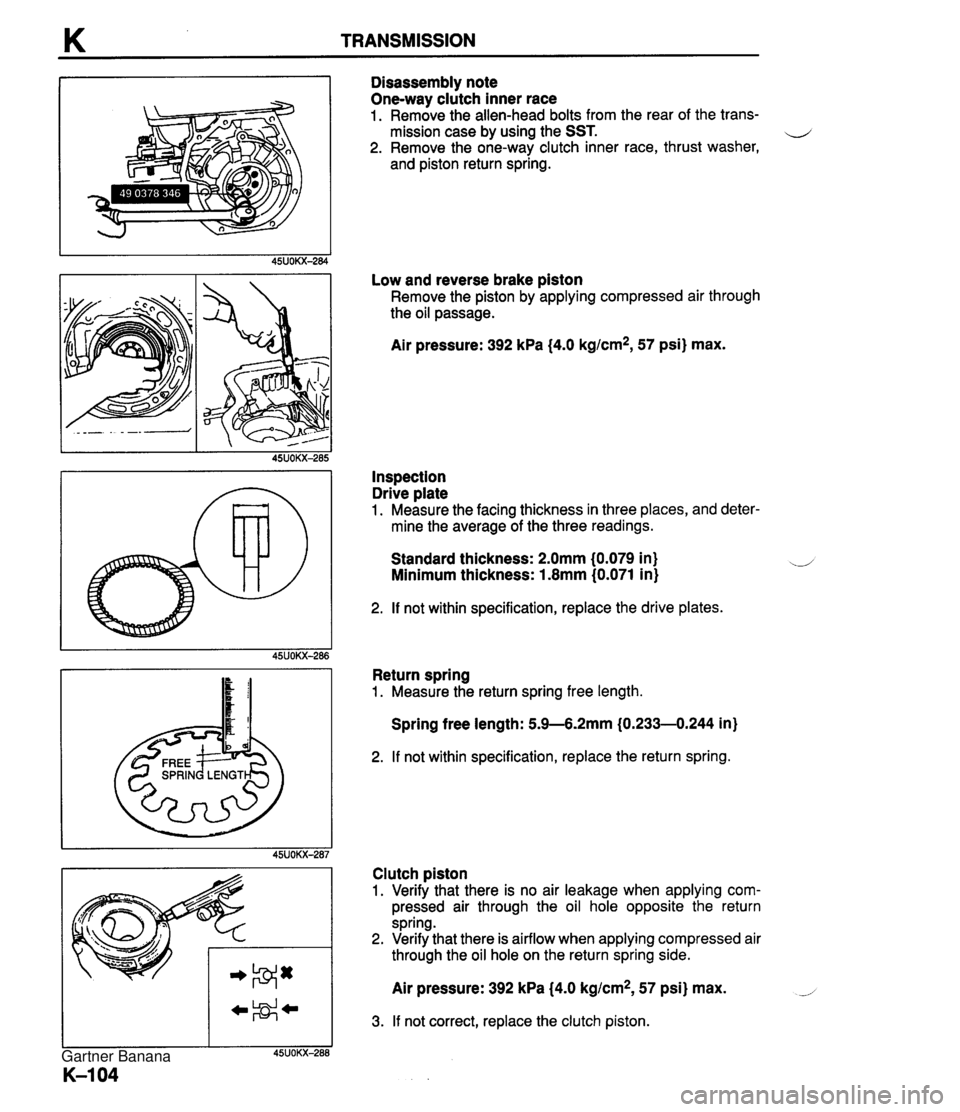
K TRANSMISSION Disassembly note One-way clutch inner race 1. Remove the allen-head bolts from the rear of the trans- mission case by using the SST. 4 2. Remove the one-wav clutch inner race, thrust washer, and piston return spring. Low and reverse brake &ton Remove the piston by gpplying compressed air through the oil passage. Air pressure: 392 kPa (4.0 kg/cm2, 57 psi) max. Inspection Drive plate 1. Measure the facing thickness in three places, and deter- mine the average of the three readings. Standard thickness: 2.0mm (0.079 in) Minimum thickness: 1.8mm (0.071 in) 2. If not within specification, replace the drive plates. Return spring 1. Measure the return spring free length. Spring free length: 5.9-6.2mm (0.233-0.244 in) 2. If not within specification, replace the return spring. Clutch piston 1. Verify that there is no air leakage when applying com- pressed air through the oil hole opposite the return spring. 2. Verify that there is airflow when applying compressed air through the oil hole on the return spring side. Air pressure: 392 kPa (4.0 kg/cm2, 57 psi) max. 3. If not correct, replace the clutch piston. Gartner Banana
Page 507 of 1708
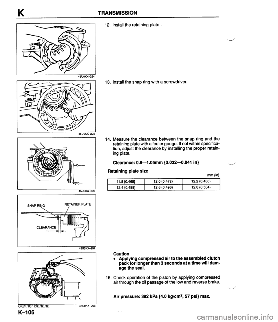
K TRANSMISSION SNAP RING RETAINER PLATE 12. lnstall the retaining plate . 13. Install the snap ring with a screwdriver. 14. Measure the clearance between the snap ring and the retaining plate with a feeler gauge. If not within specifica- tion, adjust the clearance by installing the proper retain- ing plate. Clearance: 0.8-1.05mm (0.032-4.041 in) d Retaining plate size rnrn {in) Caution Applying compressed air to the assembled clutch pack for longer than 3 seconds at a time will dam- age the seal. 15. Check operation of the piston by applying compressed air through the oil passage of the low and reverse brake. _i Air pressure: 392 kPa (4.0 kglcm*, 57 psi) max. Gartner Banana
Page 508 of 1708

TRANSMISSION K EXTENSION HOUSING AND PARKING MECHANISM Disassembly 1 Inspection 1 Assembly u Note The oil seal does not have to be removed unless it is being replaced. 1. Disassemble in the order shown in the figure, referring to Disassembly Note. 2. Inspect all parts, and repair or replace if necessary. 3. Assemble in the reverse order of disassembly, referring to Assembly procedure. . - Extension housing 15. Manual shaft 1 2. Dowel spacer 3. Return spring 4. Parking pawl 5. Pawl shaft 6. Retainer plate 7. Actuator support 8. Steel ball 9. Retainer 10. Spring Inspection .................. page K-108 11. Spring pin 12. Retaining ring 13. Manual plate 14. Parking rod 16. O-ring 17. O-ring 18. Oil distributor Inspection ................ page K-108 19. Seal rings 20. Transmission case 21. Output shaft 22. Snap ring 23. Speedometer drive gear 24. Key 25. Snap ring 26. Oil seal Disassembly note ........... page K-108 Gartner Banana
Page 509 of 1708
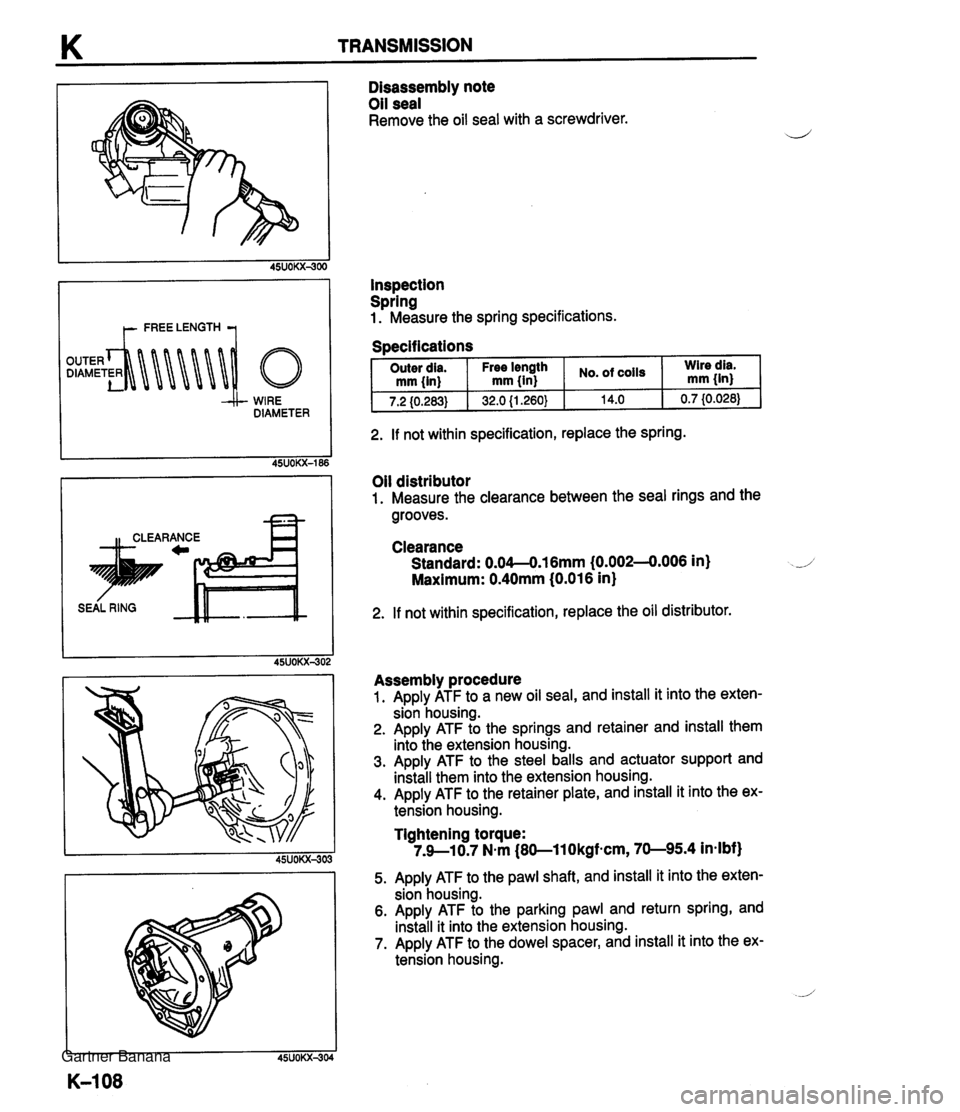
K TRANSMISSION t- FREE LENGTH 1 WIRE DIAMETER n CLEARANCE -a Disassembly note Oil seal Remove the oil seal with a screwdriver. Inspection Spring 1. Measure the spring specifications. Specifications . I Outer dia. 2. If not within specification, replace the spring. Oil distributor 1. Measure the clearance between the seal rings and the grooves. - -. - . - - mm {in) 7.2 (0.283) Clearance Standard: 0.04--0.16mm (0.0024.006 in) Maximum: 0.40mm (0.016 in} No. of coils 14.0 Free length mm {in} 32.0 {I .260} 2. If not within specification, replace the oil distributor. Wire dia. mm 0.7 I0.028) Assembly procedure 1. Apply ATF to a new oil seal, and install it into the exten- sion housing. 2. Apply ATF to the springs and retainer and install them into the extension housing. 3. Apply ATF to the steel balls and actuator support and install them into the extension housing. 4. Apply ATF to the retainer plate, and install it into the ex- tension housing. Tightening torque: 7.9--10.7 Nmm (80-11 Okgfmcm, 70-95.4 in-lbf) 5. Apply ATF to the pawl shaft, and install it into the exten- sion housing. 6. Apply ATF to the parking pawl and return spring, and install it into the extension housing. 7. Apply ATF to the dowel spacer, and install it into the ex- tension housing. Gartner Banana
Page 510 of 1708

TRANSMISSION K 8. Apply ATF to the new O-rings, and install them onto the manual shaft. 9. Apply ATF to the manual shaft, and install it into the transmission case. 10. Install the parking rod and retaining ring. 11. Apply ATF to the manual plate, and install it onto the manual shaft. 12. Drive the spring pin. 13. Check the parking mechanism operation. 14. Apply ATF to the new seal rings, and install them onto the oil distributor. 15. Install the snap ring, key, and speedometer drive gear onto the output shaft. 16. Secure the speedometer drive gear with the snap ring. Gartner Banana
Page 512 of 1708
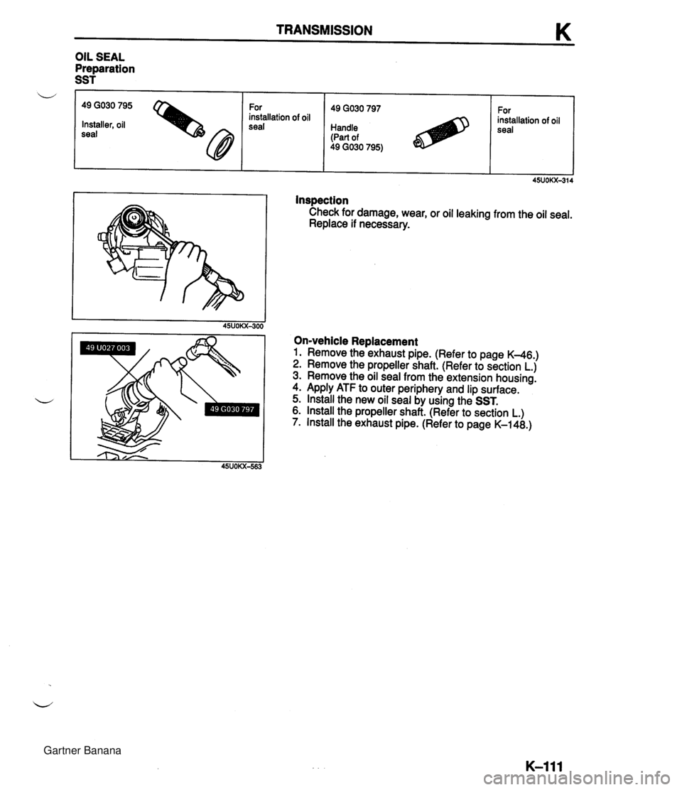
TRANSMISSION K Inspection Check for damage, wear, or oil leaking from the oil seal. Replace if necessary. OIL SEAL Preparation SST On-vehicle Replacement 1. Remove the exhaust pipe. (Refer to page K-46.) 2. Remove the propeller shaft. (Refer to section L.) 3. Remove the oil seal from the extension housing. 4. Apply ATF to outer periphery and lip surface. 5. Install the new oil seal by using the SST. 6. lnstall the propeller shaft. (Refer to section L.) 7. Install the exhaust pipe. (Refer to page K-148.) w 49 GO30 795 For installation of oil Installer, oil seal 49 GO30 797 Handle (Part of 49 GO30 795) For installation of oil seal Gartner Banana