clutch MAZDA MX-5 1994 User Guide
[x] Cancel search | Manufacturer: MAZDA, Model Year: 1994, Model line: MX-5, Model: MAZDA MX-5 1994Pages: 1708, PDF Size: 82.34 MB
Page 154 of 1708

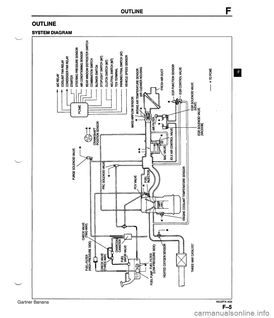
PURGE SOLENOID VALVE 7* AlC RELAY COOLANT FAN RELAY CONDENSER FAN RELAY STARTER STEERING PRESSURE SENSOR AIR CONDITIONING SENSOR ... CHECK VALVE FUEL-FILTER (HIGH-PRESSURE SIDE) / CRANKSHAFT POSITION SENSOR HEATED OXYGEN SENSOR ltT=I THREE-WAY CATALYST - REAR WINDOW DEFROSTER SWITCH COMBINATION SrmCH BLOWER SWlTCH STOPLIGHT SWITCH (MT) CLUTCH SWITCH (MT) - NEUTRALSWrrCH (MT) TEN TERMINAL PARWEUTRAL SWITCH (AT) VEHICLE SPEED SENSOR ENGINE COOLAMTEMPERATURE SENSOR EGR SOLENOID VALVE WEM) EGR SOLENOID VALVE (VACUUM) - w TO PCME Gartner Banana
Page 158 of 1708

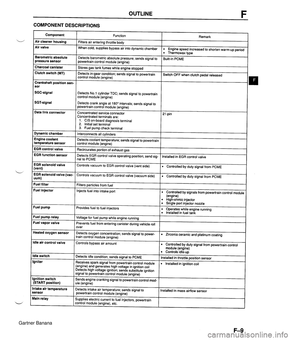
OUTLINE F COMPONENT DESCRIPTIONS Component Air cleaner housing Air valve Remark Function Filters air entering throttle body When cold, supplies bypass air into dynamicchamber w Engine speed increased to shorten warm-up period Thermowax type Barometric absolute pressure sensor Detects barometric absolute pressure; sends signal to powertrain control module (engine) 3uilt-in PCME Charcoal canister Clutch switch (MT) Stores gas tank fumes while engine stopped Detects in-gear condition: sends signal to powertrain control module (engine) --- ~witch OFF when clutch pedal released Crankshaft position sen- sor Detects No.1 cylinder TDC; sends signal to powertrain control module (engine) Detects crank angle at 180" intervals; sends signal to powertrain control module (engine) Data link connector Concentrated service connector Concentrated terminals are: 1. CIS on-board diagnosis terminal 2. Initial set terminal 3. Fuel pump check terminal Dynamic chamber Interconnects all cylinders Detects coolant temperature; sends signal to powertrain control module (engine) Recircurates oortion of exhaust aas Engine coolant temperature sensor EGR control valve lnstalled in EGR control valve EGR function sensor Detects EGR control valve operating position; send sig- nal to PCME EGR solenoid valve (vent) Controls vacuum to EGR control valve (vent side) Controlled by duty signal from PCME . - EGR solenoid valve (vac- Controls vacuum to EGR control valve (vacuum side) 0 Controlled by duty signal from PCME uum) Fuel filter Filters particles from fuel Injects fuel into intake port Fuel injector Controlled by signals from powertrain control module (engine) High-ohmic injector 0 Sinale port injector nozzle Fuel pump Provides fuel to fuel injectors 0 operates while engine running lnstalled in fuel tank Fuel pump relay Voltage for fuel pump while engine running Fuel vapor valve Prevents fuel from entering canister during vehicle roll over Heated oxygen sensor Detects oxygen concentration; sends signal to power- train control module (engine) 0 Zirconia ceramic and platinum coating ldle air control valve Controls bypass air amount Controlled by duty signal from powertrain control module (engine) Controls idle-up lnstalled in throttle position sensor lnstalled in ignition coil ldle switch Igniter Detects idle condition; sends signal to PCME Receives spark signal from powertrain control module (engine) and generates high voltage in ignition coil Detects high voltage ignition; sends substitute ignition signal to powertrain control module (engine) Ignition switch (START position) Sends engine cranking signal to powertrain control mod- ule (engine) Intake air temperature sensor Detects intake air temperature: sends signal to powertrain control module (engine) Installed in mass airflow sensor Main relay Supplies electric current to fuel injectors, powertrain control module (engine), etc. Gartner Banana
Page 161 of 1708

TROUBLESHOOTING GUIDE RELATIONSHIP CHART Fuel injector TEN Terminal (Data link connector) Ignition Switch (Start Position) Steering Pressure Sensor X X X X X X X X X X X X X X X xoo Blower Switch Headlight Switch Stoplight Switch Neutral and Clutch Switches (MT) Parklneutral switch (AT) Air Conditioning Sensor Idle Switch Throttle I BDL) Position Sensor I Sensor (NO) Barometric Absolute Pres- sure Sensor IGF Signal Heated Oxygen Sensor Engine Coolant Temperature Sensor Sensor Mass Air- flow Sensor Intake Air Temperature Sensor Crankshaft SGTSignal Position Sensor SGC-Signal Gartner Banana
Page 206 of 1708

TROUBLESHOOTING GUIDE F 24 Overloaded ) Low intake air amount Throttle valve not oDen fully LACK OF POWER ESCRIPmH - TEP - 1 - 2 : Performance poor under load Reduced maximum speed :heck factors other than engine Clutch slipping as Section H Brake dragging Section P Low tire pressure as Section Q Unrecommended tire size Section Q ;heck if throttle valve wide open throttles when lepressing accelerator fully rROUBLESHOOTlNG HINTS] Factors other than engine malfunction O AirlFuel mixture too lean or too rich Clutch slipping Fuel line pressure low or high Brake dragging Insufficient fuel injection Low tire pressure @ Poor ignition Unrecommended tire size 8 Low engine compression >heck if "00 is displayed on Self-Diagnosis Check- !r with ignition switch ON page F-79 :heck switches for correct operation with Self- Diagnosis Checker Monitor Lamp and ignition switch ON as page F-95 SELECT SW A YSTEM SELECT 1 - Yes Yes Clogged intake air system - INSPECTION I - C 0 0 0 0 - c C - ( E -- I I i I I No - Yes No - Yes - No ACTION %to next step 20 to next step Sheck if accelerator cable is correctly installed page F-103 3 If OK, check throttle body @r page F-101 3 If not OK, install accelerator cable correctly page F-103 - 30 to next step Diagnostic Trouble Code No. displayed Check for cause (Refer to specified check sequence) page F-81 "88" flashes Check PCME terminal 1 E voltage @r page F-145 Specification: Battery positive voltage (Ignition switch ON) o If OK, replace PCME page F-143 O If not OK, check wiring between PCME and Self-Diagno- sis Checker E+T page F-7 Go to next step -- Lamp not ONlOFF with specified switch Check for cause (Refer to specified check sequence) page F-96 Lamp always ON Check wiring between PCME terminal 1 D and Self-Diag- nosis Checker @r page F-7 Gartner Banana
Page 210 of 1708
![MAZDA MX-5 1994 User Guide TROUBLESHOOTING GUIDE TROUBLESHOOTING HINTS] D Factors other than engine malfunction Clutch slipping Brake dragging Low tire pressure Unrecommended tire size 25 O AirIFuel mixture too lean or too rich MAZDA MX-5 1994 User Guide TROUBLESHOOTING GUIDE TROUBLESHOOTING HINTS] D Factors other than engine malfunction Clutch slipping Brake dragging Low tire pressure Unrecommended tire size 25 O AirIFuel mixture too lean or too rich](/img/28/57072/w960_57072-209.png)
TROUBLESHOOTING GUIDE TROUBLESHOOTING HINTS] D Factors other than engine malfunction Clutch slipping Brake dragging Low tire pressure Unrecommended tire size 25 O AirIFuel mixture too lean or too rich Fuel line pressure low or high Insufficient fuel injection @ Poor ignition 6 Low engine compression POOR ACCELERATION Overloaded D Low intake air amount Throttle valve not open fully Clogged intake air system )ESCRIPTION I Performance poor while accelerating INSPECTION :heck factors other than engine Clutch slipping Section H D Brake dragging Section P t Low tire pressure Section Q D Unrecommended tire size Section Q :heck if throttle valve wide open throttles when jepressing accelerator fully Check if "00" is displayed on Self-Diagnosis Check- er with ignition switch ON page F-79 Check switches for correct operation with Self- Diagnosis Checker Monitor Lamp and ignition switch ON page F-95 SELECT SW A SYSTEM SELECT 1 - Yes - No Yes - No - Yes - No Yes - No ACTION Go to next step Repair Go to next step Check if accelerator cable is correctly installed * page 0 If OK, check throttle body ce Page 0 If not OK, install accelerator cable correctly page Go to next step -- Diagnostic Trouble Code No. displayed Check for cause (Refer to specified check sequenc US page "88" flashes Check PCME terminal 1 E voltage Us Page Specification: Battery positive voltage (Ignition switch ON) 0 If OK, replace PCME * Page 9 If not OK, check wiring between PCME and Self- sis Checker * Page Go to next step Lamp not ONlOFF with specified switch Check for cause (Refer to specified check sequenc * Paw Lamp always ON Check wiring between PCME terminal 1 D and Self nosis Checker * Page ! F-103 ! F-101 I F-103 :e) r F-81 ! F-145 I F-143 Diagno- ! F-7 :e) ! F-96 -Diag- ! F-7 Gartner Banana
Page 220 of 1708
![MAZDA MX-5 1994 User Guide TROUBLESHOOTING GUIDE F POOR FUEL ECONOMY I [TROUBLESHOOTING HINTS] Nhile fuel consumption is drastically increased during city driving, short-run operation, stop and go driving, extended winterwarm- MAZDA MX-5 1994 User Guide TROUBLESHOOTING GUIDE F POOR FUEL ECONOMY I [TROUBLESHOOTING HINTS] Nhile fuel consumption is drastically increased during city driving, short-run operation, stop and go driving, extended winterwarm-](/img/28/57072/w960_57072-219.png)
TROUBLESHOOTING GUIDE F POOR FUEL ECONOMY I [TROUBLESHOOTING HINTS] Nhile fuel consumption is drastically increased during city driving, short-run operation, stop and go driving, extended winterwarm- ~p periods, etc., as opposed to "trip" mileage, an attempt should be made to determine these factors when confronted with "poor mileage" conditions. However, since the operator is not always at fault, the following is offered. 3 Operator depressing accelerator more than usual due to O Alcohol blended fuel used low engine power @ High vehicle load Poor ignition Low tire pressure Low intake air amount Unrecommended tire used Electric spark advance control malfunction Brake dragging Clutch slipping @ Fuel cut control malfunction Exhaust component restricted @ High idle speed AirIFuel mixture too rich High fuel line pressure INSPECTION Check factors other than engine Low tire pressure Section Q Unrecommended tire used @zT Section Q Clutch slipping Section H Brake dragging Section P Exhaust component restricted @zT page F-128 ACTION - Yes Go to next step Repair Check if air hoses are connected correctly @zT page F-99 Yes - No Go to next step Repair @zT page F-99 Check if air cleaner element is clean page F-76 Yes - No Go to next step Replace page 699 Check if "00" is displayed on Self-Diagnosis Check- er with ignition switch ON @zT page F-79 Yes Go to next step SELECT SW A SYSTEM SELECT 1 Diagnostic Trouble Code No. displayed Check for cause (Refer to specified check sequence) page F-81 "88" flashes Check PCME terminal 1 E voltage US page F-145 Specification: Battery positive voltage (Ignition switch ON) 6 If OK, replace PCME page F-143 6 If not OK, check wiring between PCME and Self-Diagno- sis Checker page F-7 Check switches for correct operation with Self- Diagnosis Checker Monitor Lamp and ignition switch ON page F-95 SELECT SW A Yes Go to next step ~~p Lamp not ONIOFF with specified switch Check for cause (Refer to specified check sequence) @zT page F-96 Lamp always ON Check wiring between PCME terminal 1 F and Self-Diag- nosis Checker us page F-7 Gartner Banana
Page 223 of 1708
![MAZDA MX-5 1994 User Guide F TROUBLESHOOTING GUIDE DESCRIPTION I Blower fan operates but cool air not expelled ITROUBLESHOOTING HINTS] Open or short circuit in wiring harness NC relay malfunction 34 Air conditioning sensor malf MAZDA MX-5 1994 User Guide F TROUBLESHOOTING GUIDE DESCRIPTION I Blower fan operates but cool air not expelled ITROUBLESHOOTING HINTS] Open or short circuit in wiring harness NC relay malfunction 34 Air conditioning sensor malf](/img/28/57072/w960_57072-222.png)
F TROUBLESHOOTING GUIDE DESCRIPTION I Blower fan operates but cool air not expelled ITROUBLESHOOTING HINTS] Open or short circuit in wiring harness NC relay malfunction 34 Air conditioning sensor malfunction Magnetic clutch malfunction PCME malfunction AIC DOES NOT WORK INSPECTION ;round terminal B at NC relay with jumper wire Yes tnd check if condenser fan operates when ignition ;witch is turned ON #C RELAY I ;round terminal B at PCME 1 J terminal with jump- Yes ,r wire and check if condenser fan operates when gnition switch is turned ON - No :heck if Air conditioning sensor is OK Yes Section U ACTION 30 to next step 30 to A/C system Troubleshooting Section U 30 to next step qepair wire between PCME and A/C relay page F-7 Try known good PCME page F-144 ;heck Air conditioning sensor and wiring Section U Gartner Banana
Page 244 of 1708

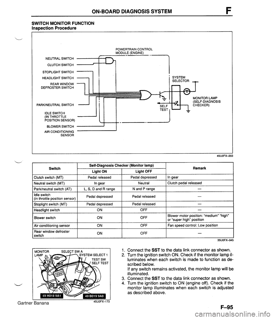
ON-BOARD DIAGNOSIS SYSTEM SWITCH MONITOR FUNCTION Inspection Procedure POWERTRAIN CONTROL MODULE (ENGINE) NEUTRAL SWITCH CLUTCH SWITCH 1 STOPLIGHT SWITCH HEADLIGHT SWITCH REAR WINDOW DEFROSTER SWITCH PARKINEUTRAL SWITCH IDLE SWITCH (IN THROTTLE POSITION SENSOR) BLOWER SWITCH AIR CONDITIONING SENSOR I ' SYSTEM MONITOR LAMP (SELF-DIAGNOSIS 1 Clutch switch (MT) 1 Pedal released I Pedal depressed I In gear I Switch Self-Diagnosis Checker (Monitor lamp) I Liaht ON Liaht OFF . . I I I - I Idle switch (in throttle position sensor) I Pedal depressed I Pedal released 1 Remark ParWneutral switch (AT) I L, S, D and R range I N and P range I I I Stoplight switch (MT) Pedal depressed I Pedal released - I Neutral I Clutch pedal released Neutral switch (MT) - In gear I I Blower switch Headlight switch OFF Blower motor position: "medium" "high" or "super hiah" position I I ON 1. Connect the SST to the data link connector as shown. 2. Turn the ignition switch ON. Check if the monitor lamp il- luminates when each switch is made to function as de- scribed below. If any switch remains activated, the monitor lamp will be illuminated. 3. Connect the SST to the data link connector as shown. 4. Turn the ignition switch to ON (engine off). Check if the monitor lamp illuminates when each switch is adjusted as described above. 45UOFX-173 OFF 1 Air conditioning sensor Rear window defroster switch - ON ON OFF OFF Fan speed control: Low position - Gartner Banana
Page 245 of 1708

F ON-BOARD DIAGNOSIS SYSTEM Procedure - Set conditions to deactivate each switch a All accessories OFF a Transmission in neutral a All pedals released Verify that monitor lamp does not illuminate Neutral and Clutch switches (MT) Parklneutral switch (AT) Depress clutch pedal Verify that monitor lamp does not illuminate Return transmission to neutral NO PC: a Neutral or clutch switch malfunction (Refer to F-146) a Open circuit in related wire harness a Powertrain control module (engine) terminal 1V malfunction (Refer to page F-146) - Shift transmission into gear Verify that monitor lamp illuminates with clutch pedal is re- leased PC: a Clutch switch malfunction (Refer to page F-157) 35UOFX-046 I ParWneutral switch OK Shift into P or N range Check each switch and related wire harness a Clutch and Neutral switch :Refer to page F-I57 a Idle switch (in throttle position sensor) :Refer to page F-154 a Stoplight switch :Refer to Section T Headlight switch :Refer to Section T 1 Check each switch as described I I NO - ldle switch (in throttle position sensor) a Blower switch :Refer to Section T a Air conditioning sensor :Refer to Section U a Rear window defroster switch :Refer to Section T a ParWneutral switch :Refer to Section K YES PC: a ParWneutral switch malfunction (Refer to Section K) a Open or short circuit in related wire harness a PCME terminal 1 V voltage incorrect (Refer to page F-I 46) PCME malfunction - Shift transmission into L, S, D, or P range Check that monitor lamp illuminates 35UOFX-06 NO + YES I 1 I ldle switch OK I L I PC: Throttle position sensor malfunction (Refer to page F-144) a Short circuit in wire harness from throttle position sensor to PCME a PCME terminal 1 N voltage incorrect (Refer to page F-145) a PCME malfunction - Depress accelerator pedal and check that monitor lamp illu- minates f NO --c YES PC: a Throttle position sensor malfunction (Refer to page F-144) Open circuit in wire harness from throttle position sensor to PCME PCME terminal 2M voltage incorrect (Refer to page F-146) Release acceleration pedal and check that monitor lamp does not illuminate 2 YES I I Gartner Banana
Page 271 of 1708

PRESSURE REGULATOR CONTROL SYSTEM PRESSURE REGULATOR CONTROL SYSTEM DATA LINK CONNECTOR - CLUTCH SWITCH (MT) (TEN TERMINAL) PARKINEUTRAL SWITCH (PCMT) (AT) THROTTLE POSITION SENSOR L 1 ,,,, INTAKE AIR TEMPERATURE 1 SENSOR (IN MASS AIRFLOW SENSOR) -;- ENGINE COOLANT TEMPERATURE SENSOR PRC SOLENOID VALVE CRANKSHAFT POSITION SENSOR PRESSURE REGULATOR PCME I Above 90°C {194OF} ( Above 70°C {158'F} I Throttle valve closed throttle position or no load condition I Approx. 150 1 I Operating condition Coolant temperature I Intake air temperature I Engine condition I I To prevent percolation of the fuel during hot restart idle, vacuum to the pressure regulator is momentarily cut, and the fuel injection pressure is increased to slightly more than 284 kPa (2.9 kgf/cm2, 41.2 psi}. Operating time (sec) Gartner Banana