transmission MAZDA MX-5 1994 User Guide
[x] Cancel search | Manufacturer: MAZDA, Model Year: 1994, Model line: MX-5, Model: MAZDA MX-5 1994Pages: 1708, PDF Size: 82.34 MB
Page 123 of 1708

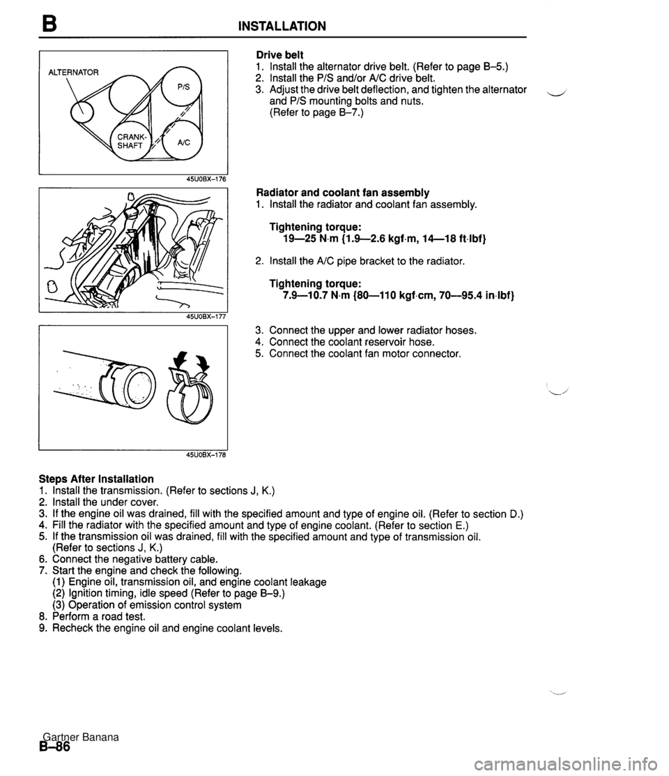
B INSTALLATION ALTERNATOR Drive belt 1. lnstall the alternator drive belt. (Refer to page B-5.) 2. lnstall the PIS and/or AIC drive belt. 3. Adjust the drive belt deflection, and tighten the alternator - and PIS mounting bolts and nuts. (Refer to page 8-7.) Radiator and coolant fan assembly 1. lnstall the radiator and coolant fan assembly. Tightening torque: 19-25 N.m (1.9-2.6 kgf.m, 14--18 ft4bf) 2. lnstall the AIC pipe bracket to the radiator Tightening torque: 7.9-10.7 N.m (80-110 kgf.cm, 70-95.4 in4bf) 3. Connect the upper and lower radiator hoses. 4. Connect the coolant reservoir hose. 5. Connect the coolant fan motor connector. Steps After Installation 1. lhstall the transmission. (Refer to sections J, K.) 2. lnstall the under cover. 3. If the engine oil was drained, fill with the specified amount and type of engine oil. (Refer to section D.) 4. Fill the radiator with the specified amount and type of engine coolant. (Refer to section E.) 5. If the transmission oil was drained, fill with the specified amount and type of transmission oil. (Refer to sections J, K.) 6. Connect the negative battery cable. 7. Start the engine and check the following. (1) Engine oil, transmission oil, and engine coolant leakage (2) Ignition timing, idle speed (Refer to page 59.) (3) Operation of emission control system 8. Perform a road test. 9. Recheck the engine oil and engine coolant levels. Gartner Banana
Page 132 of 1708

OIL PAN D RIGHT . . LEFT Removal Note Engine mount nut 1. Loosen the oil pan mounting bolts. 2. Remove the engine mounting nuts. 3. Lift the engine slightly with a hoist. Crossmember installation bolt and nut 1. Support the crossmember with a transmission jack. 2. Remove the crossmember installation bolts and nuts. 3. Separate the steering intermediate shaft from the pinion shaft. 4. Lower the crossmember until the clearance between the oil pan and the steering gear housing exceeds approx. 100mm (3.94 in). Oil pan 1. Remove the oil pan mounting bolts. Caution Pry tools can easily scratch the cylinder block and the oil pan contact surfaces. Prying off the oild pan can also easily bend the oil pan flange. Refer to the following instructions before remov- ing the oil pan. 2. Insert a screwdriver only at the points shown in the fig- ure. 3. Remove the oil pan. Oil baffle 1. Insert a screwdriver between the cylinder block and the oil baffle to separate them. 2. Remove the oil baffle. Installation Note Oil baffle 1. Remove all foreign material from the contact surfaces. 2. Apply a continuous bead of silicone sealant to the oil baffle along the inside of the bolt holes, and install within five minutes. Gartner Banana
Page 159 of 1708

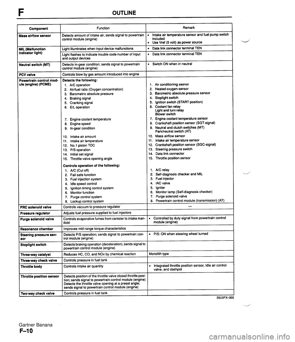
Neutral swltch (MT) 7 PCV valve Powertrain control mod- ule (engine) (PCME) Purge solenoid valve Resonance chamber Steering pressure sen- Stoplight swltch I Throttle posltion sensor r [Two-way check valve Function jetects amount of intake air; sends signal to powertrain :ontrol module (engine) Li~ht illuminates when input device malfunctions - Light flashes to indicate trouble code number of input and output devices Detects in-gear condition; sends signal to powertrain :ontrol module (engine) - Controls blow by aas amount introduced into engine Detects the followlng: 1. A/C operation 2. Airlfuel ratio (Oxygen concentration) 3. Barometric absolute pressure 4. Braking signal 5. Cranking signal 6. EIL operation 7. Engine coolant temperature 8. Engine speed 9. In-gear condition 10. lntake air amount 11, lntake air temperature 12. No.1 piston TDC 13. PIS operation 14. Initial set signal 15. Throttle valve opening angle Controls operatlon of the followlng: 1. AIC (Cut off) 2. Fail-safe function 3. Fuel injection system 4. ldle speed control 5. Ignition timing control system 6. Monitor function 7. Purge control system 8. Lockup control svstem Controls vacuum to pressure regulator -- Adjusts fuel pressure supplied to fuel injectors Controls evaporative fumes from canister to intake man- ifold -- lm~roves mid-ranae torque characteristics -. Detects PIS operation; sends signal to powertrain con- trol module (engine) -- Detects braking operation (deceleration); sends signal to powertrain control module (engine) Reduces HC, CO, and NOx by chemical reaction Controls pressurein fuel tank Controls intake air quantity Detects position of the throttle valve closed throttle posi- tion; sends signal to powertrain control module (engine) Detects the throttle valve opening at a preset angle; sends si~nal to powertrain control module (engine) controls pressure in fuel tank Remark lntake air temperature sensor and fuel pump switch included Use Vref (5 volt) as power source ' Data link connector terminal TEN ' Data link connector terminal TEN Switch ON when in neutral 1, Air conditioning sesnor 2. Heated oxygen sensor 3. Barometric absolute pressure sensor 4. Stoplight switch 5. Ignition switch (START position) 6. Coolant fan relay Light and turn relay Blower switch 7. Engine coolant temperature sensor 8. Crankshaft position sensor (SGT-signal) 9. Neutral and dutch switches (MT) Parklneutral switch (AT) 10. Mass airflow sensor 11, lntake air temperature sensor 12. Crankshaft position sensor (SGC-signal) 13. Steering pressure switch 14. Data link connector 15. Throttle position sensor 1. NC relay 2. Self-diagnosis checker and MIL 3. Fuel injector 4. IAC valve 5. Igniter 6. Monitor lamp (Self-diagnosis checker) 7. Purge solenoid valve 8. Powertrain control module (transmission) (AT) D Controlled by duty signal from powertrain control module (engine) D PIS: ON when steering wheel turned Monolith type D Integrated throttle position sensor, Idle air control valve, and dashpol Gartner Banana
Page 245 of 1708

F ON-BOARD DIAGNOSIS SYSTEM Procedure - Set conditions to deactivate each switch a All accessories OFF a Transmission in neutral a All pedals released Verify that monitor lamp does not illuminate Neutral and Clutch switches (MT) Parklneutral switch (AT) Depress clutch pedal Verify that monitor lamp does not illuminate Return transmission to neutral NO PC: a Neutral or clutch switch malfunction (Refer to F-146) a Open circuit in related wire harness a Powertrain control module (engine) terminal 1V malfunction (Refer to page F-146) - Shift transmission into gear Verify that monitor lamp illuminates with clutch pedal is re- leased PC: a Clutch switch malfunction (Refer to page F-157) 35UOFX-046 I ParWneutral switch OK Shift into P or N range Check each switch and related wire harness a Clutch and Neutral switch :Refer to page F-I57 a Idle switch (in throttle position sensor) :Refer to page F-154 a Stoplight switch :Refer to Section T Headlight switch :Refer to Section T 1 Check each switch as described I I NO - ldle switch (in throttle position sensor) a Blower switch :Refer to Section T a Air conditioning sensor :Refer to Section U a Rear window defroster switch :Refer to Section T a ParWneutral switch :Refer to Section K YES PC: a ParWneutral switch malfunction (Refer to Section K) a Open or short circuit in related wire harness a PCME terminal 1 V voltage incorrect (Refer to page F-I 46) PCME malfunction - Shift transmission into L, S, D, or P range Check that monitor lamp illuminates 35UOFX-06 NO + YES I 1 I ldle switch OK I L I PC: Throttle position sensor malfunction (Refer to page F-144) a Short circuit in wire harness from throttle position sensor to PCME a PCME terminal 1 N voltage incorrect (Refer to page F-145) a PCME malfunction - Depress accelerator pedal and check that monitor lamp illu- minates f NO --c YES PC: a Throttle position sensor malfunction (Refer to page F-144) Open circuit in wire harness from throttle position sensor to PCME PCME terminal 2M voltage incorrect (Refer to page F-146) Release acceleration pedal and check that monitor lamp does not illuminate 2 YES I I Gartner Banana
Page 297 of 1708

CONTROL SYSTEM Check Point for Each Terminal B+: Battery positive voltage Terminal -. - Connection to Abnormal voltage Possible cause Battery Always OV (Battery OK) Always OV Main relay a ROOM 10A fuse burned Open circuit in wiring from ROOM 1 OA fuse to PCME terminal 1A Main relay malfunction (Refer to page F-156) Open circuit in wiring from main relay to PCME termi- nal 1 B Ignition switch (Start position) a Main relay malfunction (Refer to page F-156) Open circuit in wiring from main relay to data link connector terminal +B Open or short circuit in wiring from data link connec- tor terminal MEN to PCME terminal 1 D Always OV (Starter turns) Always OV Open circuit in wiring from starter interlock switch to PCME terminal 1 C Self-Diagnosis Checker (Monitor lamp) Always B+ a Poor connection at PCME connector PCME malfunction I Always approx. 5V I a PCME malfunction Malfunction indicator light (MIL) Always below 2.5V (MIL always ON) Always below 2.5V Open circuit in wiring from combination meter to (MIL never ON) I PCME terminal I E a Short circuit in wiring from combination meter to PCME terminal 1 E PCME malfunction Always B+ Poor connection at PCME connector a PCME malfunction Self-Diagnosis Checker (Code No.) Always below 2.5V (No display on Self-Diagnosis Checker) Main relay malfunction (Refer to page F-156) a Open circuit in wiring from main relay to data link connector terminal +B Always B+ Always below 2.5V ("88" is displayed and buzzer sounds continuously) a Poor connection at PCME connector a PCME malfunction - Open or short circuit in wiring from data link connec- tor terminal FEN to PCME terminal I E Igniter Always OV a Refer to Code No.01 troubleshooting I (Refer to section GI Powertrain control module (transmission) Always B+ I PCME malfunction A/C relay malfunction (Refer to section U) a Open circuit in wiring from main relay to NC relay a Open circuit in wiring from NC relay to PCME termi- nal 1 J a Short circuit in wiring from NC relay to PCME termi- nal 1 J a PCME malfunction Always below 2.5V (NC does not operate) Always below 2.5V (Air conditioning sensor OFF but A/C operates) AIC relay Air conditioning sensor malfunction (Refer to section U) Poor connection at PCME connector PCME malfunction Always B+ Open circuit in wiring from PCME terminal 1 K to ground PCME malfunction Ground (MT) Always B+ Open (AT) Always OV Short circuit in wiring from PCME terminal 1 K to grounc PCME malfunction Coolant fan relay Always below 1 .OV (Coolant fan OK) Open or short circuit in wiring from fan relay to PCME terminal I L PCME malfunction Gartner Banana
Page 306 of 1708

CONTROL SYSTEM LOCK 4. If not as specified, replace the main relay. MAIN RELAY lnspection 1. Verify that the main relay clicks when turning the ignition switch OFF -+ ON. 2. Apply battery positive voltage to terminal A and ground terminal B of the main relay. 3. Use an ohmmeter to check continuity of the terminals as shown. CLUTCH SWITCH Inspection 1. Disconnect the clutch switch connector. 2. Connect an ohmmeter to the switch. 3. Check continuity of the switch. Battery positive voltage applied - Continuity - Terminals CD L 4. If not as specified, replace the clutch switch. Battery positive voltage not applied No continuity Pedal Depressed Released Replacement 1. Disconnect the clutch switch connector. 2. Loosen the locknut. 3. Remove the clutch switch. 4. Install in the reverse order of removal. 5. Adjust the pedal height. (Refer to Section H.) Continuity Yes No 4. If not as specified, replace the neutral switch. NEUTRAL SWITCH lnspection 1. Disconnect the neutral switch connector. 2. Connect an ohmmeter to the switch. 3. Check continuity of the switch. Transmission Neutral Other ranges Continuity , Yes No Gartner Banana
Page 350 of 1708

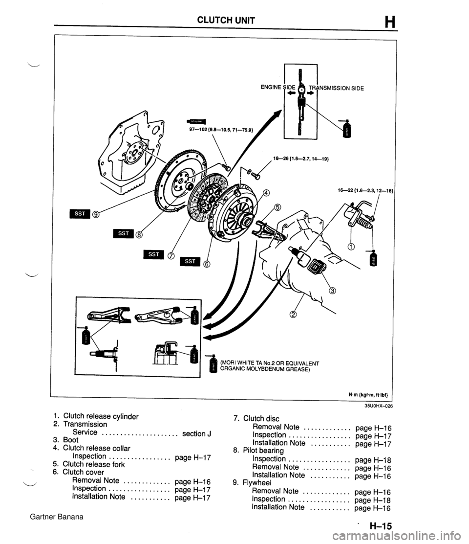
CLUTCH UNIT H 97-1 02 {O&-10.5,71-75.9) 18--26 {I .6-2.7,14-19) (MORI WHITE TA No.2 OR EQUIVALENT ORGANIC MOLYBDENUM GREASE) 1. Clutch release cylinder 2. Transmission Service ..................... section J 3. Boot 4. Clutch release collar Inspection ................. page H-17 5. Clutch release fork 6. Clutch cover Removal Note ............. page H-16 Inspection ................. page H-17 Installation Note ........... page H-17 7. Clutch disc Removal Note ............. page H-16 Inspection ................. page H-17 Installation Note ........... page H-17 8. Pilot bearing Inspection ................. page H-18 Removal Note ............. page H-16 Installation Note ........... page H-16 9. Flywheel Removal Note ............. page H-16 Inspection ................. page H-18 Installation Note ........... page H-16 Gartner Banana
Page 355 of 1708

Before beginning any service procedure. refer to section T of this manual for air bag system service warnings and audio antitheft system alarm conditions . MANUAL TRANSMISSION INDEX ....................................... J- 2 ..................................... OUTLINE J- 3 SPECIFICATIONS ........................... J- 3 ........................ STRUCTURAL VIEW J- 4 ............................. COMPONENTS J- 5 ............................. POWER FLOW J- 6 TROUBLESHOOTING GUIDE .................. J- 7 .......................... TRANSMISSION OIL J- 8 ............................... INSPECTION J- 8 ............................ REPLACEMENT J- 8 TRANSMISSION .............................. J- 9 ............................. PREPARATION J- 9 REMOVAL .................................. J-10 DISASSEMBLY ............................. J-13 ............................... INSPECTION 5-23 ASSEMBLY ................................. J-26 INSTALLATION ............................. J-45 25UOJX-011 Gartner Banana
Page 356 of 1708

J INDEX INDEX OIL SPECIFICATION API SERVICE GL-4 OR GL-5 ALL-SEASON TYPE: SAE 75W-90 ABOVE 10°C {50°F): SAE 80W-90 CAPACITY. 2.0 L {2.1 US qt, 1.8 Imp qt} 1. Transmission Removal . . . . . . . . . . . . . . . . . . . . page J-10 Disassembly . . . . . . . . . . . . . . . . page J-13 Inspection . . . . . . . . . . . . . . . . . . . page J-23 Assembly . . . . . . . . . . . . . . . . . . . page J-26 Installation . . . . . . . . . . . . . . . . . . page J-45 Gartner Banana
Page 357 of 1708

OUTLINE OUTLINE SPECIFICATIONS Transmission Item M15M-D Synchronization mechanism Forward: Synchromesh Reverse: Synchromesh Shift type Gear ratio I st 2nd 5-speed, floor shift 3.1 36 1.888 5th Reverse 0.81 4 3.758 API service GL-4 or GL-5 SAE 75W-90 SAE 80W-90 Grade ' Capacity L {US qt, Imp qt} Viscosity 2.0 12.1, 1.8) All-season Above 10°C {50°F) 45UOJX401 Gartner Banana