MAZDA MX-5 1997 Factory Workshop Manual
Manufacturer: MAZDA, Model Year: 1997, Model line: MX-5, Model: MAZDA MX-5 1997Pages: 514, PDF Size: 17.89 MB
Page 51 of 514
Sensor is a cable driven pulse generator that is part of speedometer. Pulse signals are sent to TCM.
TCM OUTPUT DEVICES
HOLD Indicator Light
Receives signal from TCM to indicate switch position.
Inhibitor Signal
When shift selector lever is moved from Park or Neutral to another gear, signal is sent from TCM to ECM to
regulate fuel injection volume for shift shock prevention.
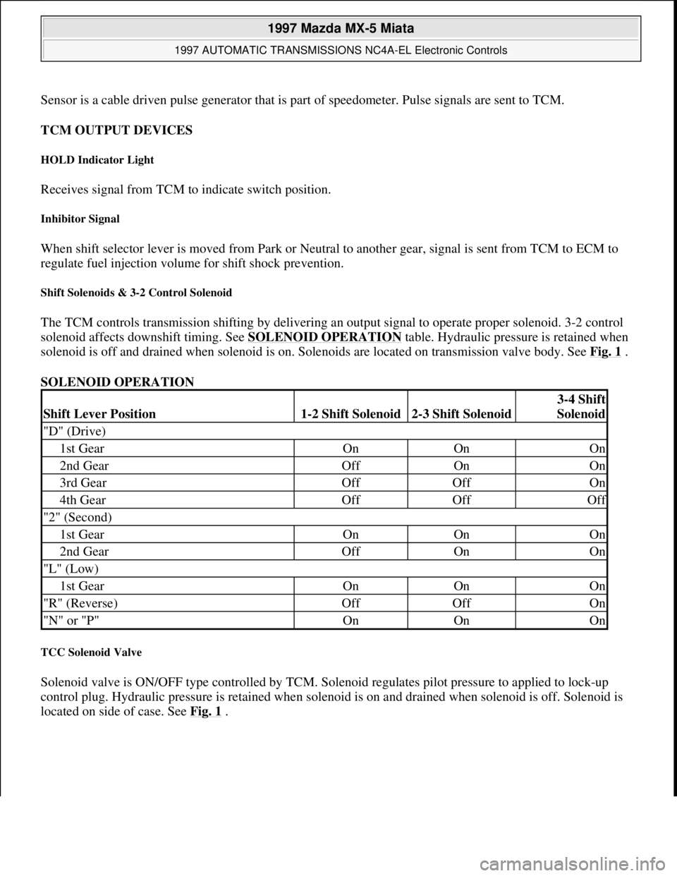
Shift Solenoids & 3-2 Control Solenoid
The TCM controls transmission shifting by delivering an output signal to operate proper solenoid. 3-2 control
solenoid affects downshift timing. See SOLENOID OPERATION
table. Hydraulic pressure is retained when
solenoid is off and drained when solenoid is on. Solenoids are located on transmission valve body. See Fig. 1
.
SOLENOID OPERATION
TCC Solenoid Valve
Solenoid valve is ON/OFF type controlled by TCM. Solenoid regulates pilot pressure to applied to lock-up
control plug. Hydraulic pressure is retained when solenoid is on and drained when solenoid is off. Solenoid is
located on side of case. See Fig. 1
.
Shift Lever Position1-2 Shift Solenoid2-3 Shift Solenoid
3-4 Shift
Solenoid
"D" (Drive)
1st GearOnOnOn
2nd GearOffOnOn
3rd GearOffOffOn
4th GearOffOffOff
"2" (Second)
1st GearOnOnOn
2nd GearOffOnOn
"L" (Low)
1st GearOnOnOn
"R" (Reverse)OffOffOn
"N" or "P"OnOnOn
1997 Mazda MX-5 Miata
1997 AUTOMATIC TRANSMISSIONS NC4A-EL Electronic Controls
Microsoft
Sunday, July 05, 2009 1:35:03 PMPage 3 © 2005 Mitchell Repair Information Company, LLC.
Page 52 of 514

Fig. 1: Locating Solenoid Valves
Courtesy of MAZDA MOTORS CORP.
SELF-DIAGNOSTIC SYSTEM
SYSTEM DIAGNOSIS
TCM monitors transmission operation and contains a self-diagnostic system which stores a Diagnostic Trouble
Code (DTC) if an electronic control system failure or component malfunction exists. If a problem exists in any
of the solenoids or speed sensors and DTC is set, TCM will deliver a signal to blink the HOLD indicator light
on instrument panel to warn the driver. DTC may be set if a failure exists and can be retrieved for transmission
diagnosis.
RETRIEVING TROUBLE CODES
NOTE: Before testing transmission, ensure fluid level is correct. Ensure engine starts
with shift lever in Park and Neutral to ensure proper adjustment of transmission
range switch. Transmission Control Module (TCM) must first be checked for
stored codes. See RETRIEVING TROUBLE CODES
.
NOTE: Before retrieving DTC, ensure proper battery voltage exists for self-diagnostic
system operation. If any DTC are present other than those listed below, see
1997 Mazda MX-5 Miata
1997 AUTOMATIC TRANSMISSIONS NC4A-EL Electronic Controls
Microsoft
Sunday, July 05, 2009 1:35:03 PMPage 4 © 2005 Mitchell Repair Information Company, LLC.
Page 53 of 514
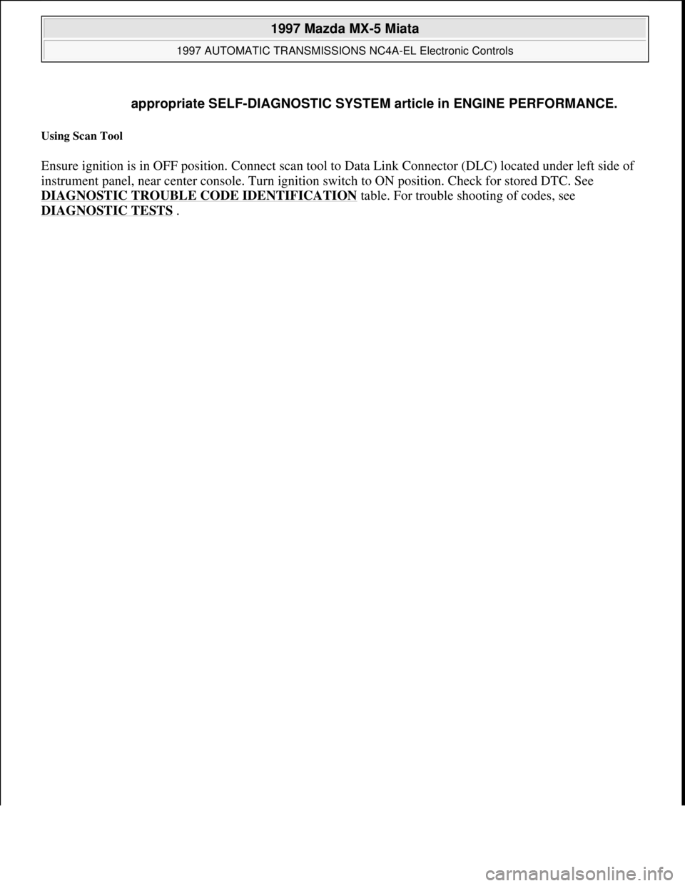
Using Scan Tool
Ensure ignition is in OFF position. Connect scan tool to Data Link Connector (DLC) located under left side of
instrument panel, near center console. Turn ignition switch to ON position. Check for stored DTC. See
DIAGNOSTIC TROUBLE CODE IDENTIFICATION
table. For trouble shooting of codes, see
DIAGNOSTIC TESTS
. appropriate SELF-DIAGNOSTIC SYSTEM article in ENGINE PERFORMANCE.
1997 Mazda MX-5 Miata
1997 AUTOMATIC TRANSMISSIONS NC4A-EL Electronic Controls
Microsoft
Sunday, July 05, 2009 1:35:03 PMPage 5 © 2005 Mitchell Repair Information Company, LLC.
Page 54 of 514
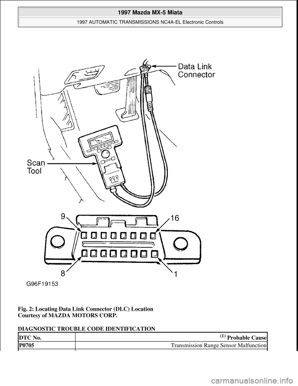
Fig. 2: Locating Data Link Connector (DLC) Location
Courtesy of MAZDA MOTORS CORP.
DIAGNOSTIC TROUBLE CODE IDENTIFICATION
DTC No.(1) Probable Cause
P0705 Transmission Range Sensor Malfunction
1997 Mazda MX-5 Miata
1997 AUTOMATIC TRANSMISSIONS NC4A-EL Electronic Controls
Microsoft
Sunday, July 05, 2009 1:35:03 PMPage 6 © 2005 Mitchell Repair Information Company, LLC.
Page 55 of 514
CLEARING CODES
To clear DTC stored in TCM, use scan tool. See scan tool instruction manual. Road test vehicle.
COMPONENT LOCATION
COMPONENT LOCATION
COMPONENT CONNECTOR IDENTIFICATION
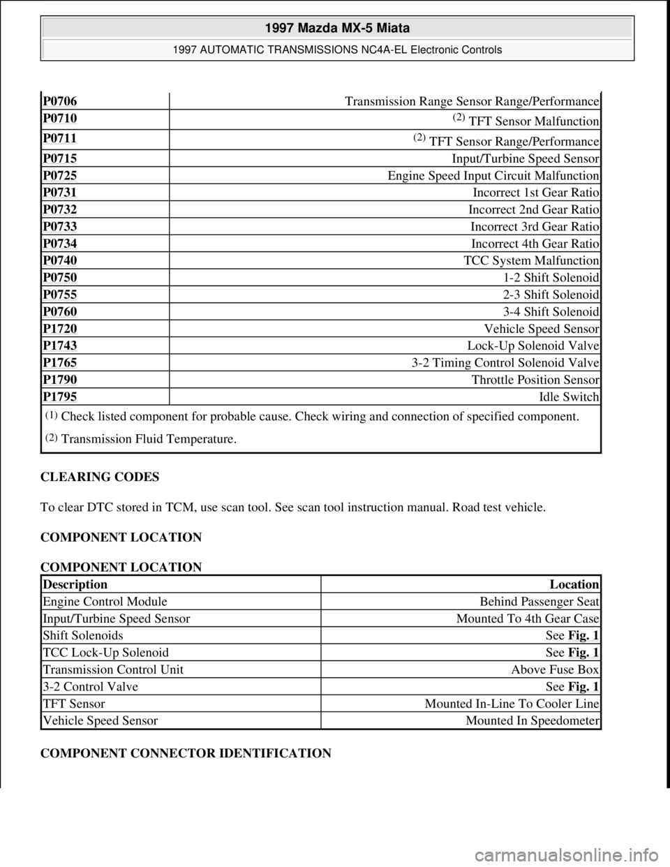
P0706 Transmission Range Sensor Range/Performance
P0710 (2) TFT Sensor Malfunction
P0711 (2) TFT Sensor Range/Performance
P0715 Input/Turbine Speed Sensor
P0725 Engine Speed Input Circuit Malfunction
P0731 Incorrect 1st Gear Ratio
P0732 Incorrect 2nd Gear Ratio
P0733 Incorrect 3rd Gear Ratio
P0734 Incorrect 4th Gear Ratio
P0740 TCC System Malfunction
P0750 1-2 Shift Solenoid
P0755 2-3 Shift Solenoid
P0760 3-4 Shift Solenoid
P1720 Vehicle Speed Sensor
P1743 Lock-Up Solenoid Valve
P1765 3-2 Timing Control Solenoid Valve
P1790 Throttle Position Sensor
P1795 Idle Switch
(1)Check listed component for probable cause. Check wiring and connection of specified component.
(2)Transmission Fluid Temperature.
DescriptionLocation
Engine Control ModuleBehind Passenger Seat
Input/Turbine Speed SensorMounted To 4th Gear Case
Shift SolenoidsSee Fig. 1
TCC Lock-Up SolenoidSee Fig. 1
Transmission Control UnitAbove Fuse Box
3-2 Control ValveSee Fig. 1
TFT SensorMounted In-Line To Cooler Line
Vehicle Speed SensorMounted In Speedometer
1997 Mazda MX-5 Miata
1997 AUTOMATIC TRANSMISSIONS NC4A-EL Electronic Controls
Microsoft
Sunday, July 05, 2009 1:35:03 PMPage 7 © 2005 Mitchell Repair Information Company, LLC.
Page 56 of 514
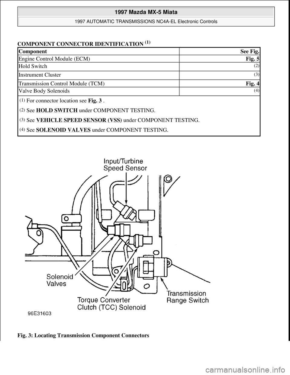
COMPONENT CONNECTOR IDENTIFICATION (1)
Fig. 3: Locating Transmission Component Connectors
ComponentSee Fig.
Engine Control Module (ECM)Fig. 5
Hold Switch(2)
Instrument Cluster(3)
Transmission Control Module (TCM)Fig. 4
Valve Body Solenoids(4)
(1)For connector location see Fig. 3 .
(2)See HOLD SWITCH under COMPONENT TESTING.
(3)See VEHICLE SPEED SENSOR (VSS) under COMPONENT TESTING.
(4)See SOLENOID VALVES under COMPONENT TESTING.
1997 Mazda MX-5 Miata
1997 AUTOMATIC TRANSMISSIONS NC4A-EL Electronic Controls
Microsoft
Sunday, July 05, 2009 1:35:03 PMPage 8 © 2005 Mitchell Repair Information Company, LLC.
Page 57 of 514
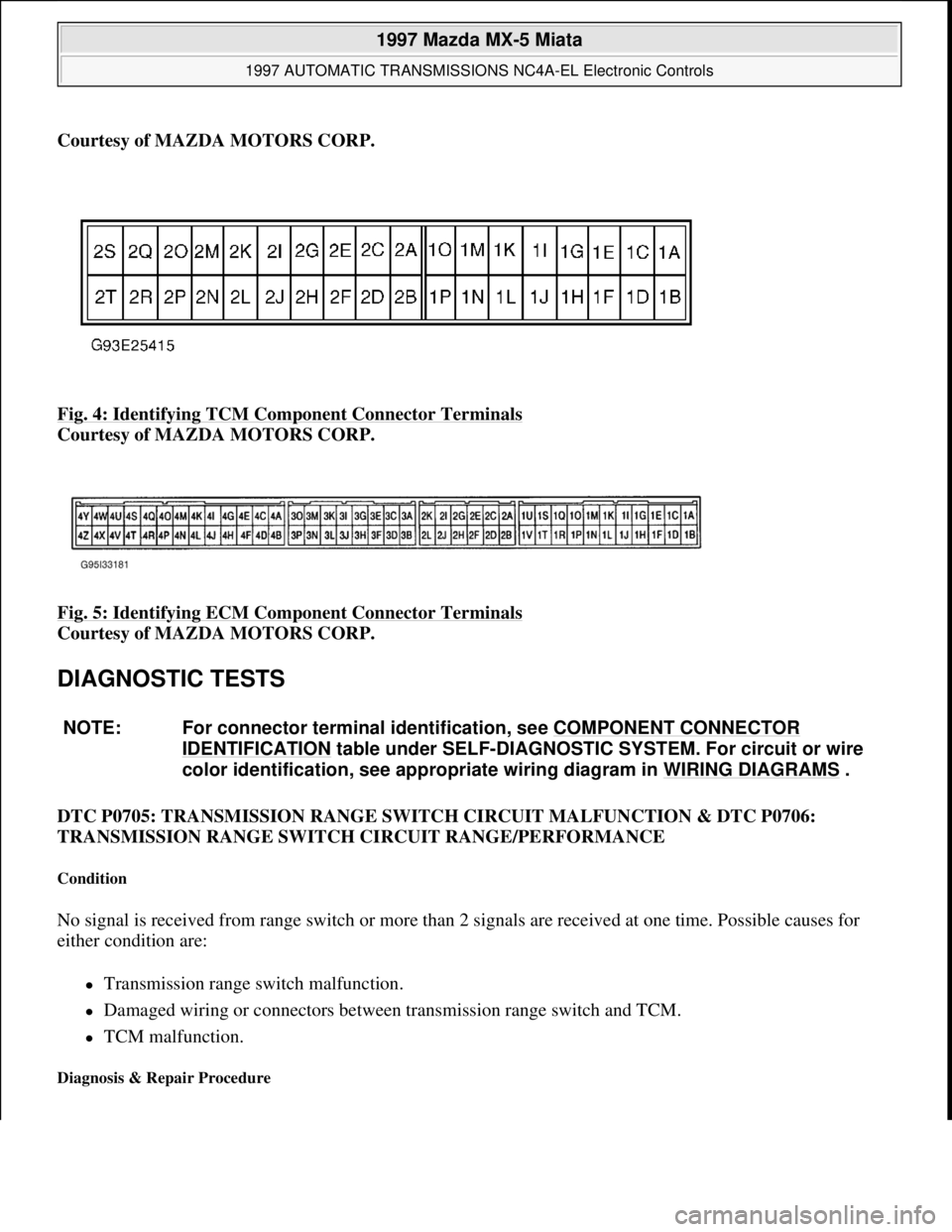
Courtesy of MAZDA MOTORS CORP.
Fig. 4: Identifying TCM Component Connector Terminals
Courtesy of MAZDA MOTORS CORP.
Fig. 5: Identifying ECM Component Connector Terminals
Courtesy of MAZDA MOTORS CORP.
DIAGNOSTIC TESTS
DTC P0705: TRANSMISSION RANGE SWITCH CIRCUIT MALFUNCTION & DTC P0706:
TRANSMISSION RANGE SWITCH CIRCUIT RANGE/PERFORMANCE
Condition
No signal is received from range switch or more than 2 signals are received at one time. Possible causes for
either condition are:
Transmission range switch malfunction.
Damaged wiring or connectors between transmission range switch and TCM.
TCM malfunction.
Diagnosis & Repair Procedure
NOTE: For connector terminal identification, see COMPONENT CONNECTOR
IDENTIFICATION table under SELF-DIAGNOSTIC SYSTEM. For circuit or wire
color identification, see appropriate wiring diagram in WIRING DIAGRAMS
.
1997 Mazda MX-5 Miata
1997 AUTOMATIC TRANSMISSIONS NC4A-EL Electronic Controls
Microsoft
Sunday, July 05, 2009 1:35:03 PMPage 9 © 2005 Mitchell Repair Information Company, LLC.
Page 58 of 514
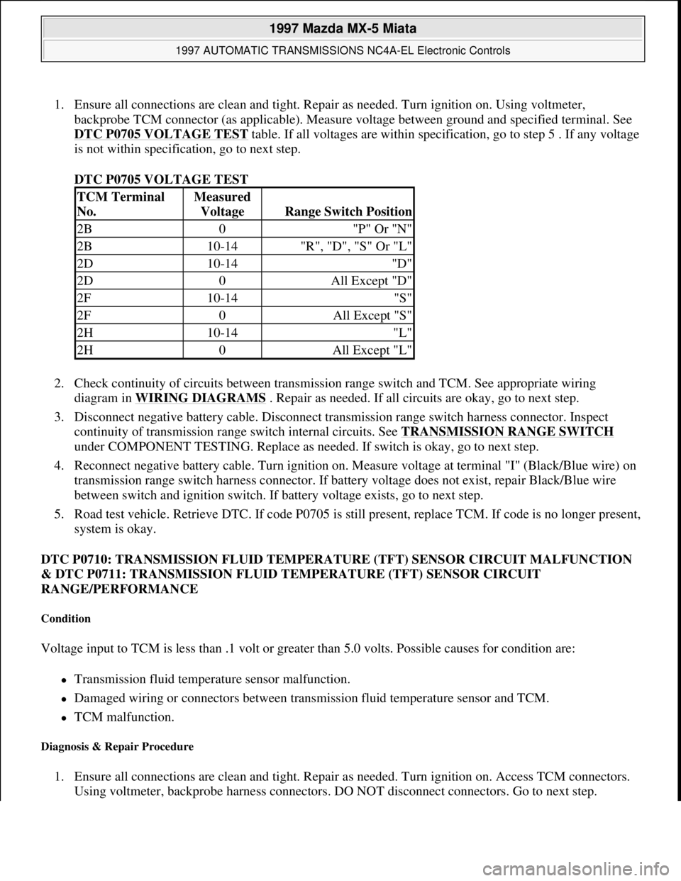
1. Ensure all connections are clean and tight. Repair as needed. Turn ignition on. Using voltmeter,
backprobe TCM connector (as applicable). Measure voltage between ground and specified terminal. See
DTC P0705 VOLTAGE TEST
table. If all voltages are within specification, go to step 5 . If any voltage
is not within specification, go to next step.
DTC P0705 VOLTAGE TEST
2. Check continuity of circuits between transmission range switch and TCM. See appropriate wiring
diagram in WIRING DIAGRAMS
. Repair as needed. If all circuits are okay, go to next step.
3. Disconnect negative battery cable. Disconnect transmission range switch harness connector. Inspect
continuity of transmission range switch internal circuits. See TRANSMISSION RANGE SWITCH
under COMPONENT TESTING. Replace as needed. If switch is okay, go to next step.
4. Reconnect negative battery cable. Turn ignition on. Measure voltage at terminal "I" (Black/Blue wire) on
transmission range switch harness connector. If battery voltage does not exist, repair Black/Blue wire
between switch and ignition switch. If battery voltage exists, go to next step.
5. Road test vehicle. Retrieve DTC. If code P0705 is still present, replace TCM. If code is no longer present,
system is okay.
DTC P0710: TRANSMISSION FLUID TEMPERATURE (TFT) SENSOR CIRCUIT MALFUNCTION
& DTC P0711: TRANSMISSION FLUID TEMPERATURE (TFT) SENSOR CIRCUIT
RANGE/PERFORMANCE
Condition
Voltage input to TCM is less than .1 volt or greater than 5.0 volts. Possible causes for condition are:
Transmission fluid temperature sensor malfunction.
Damaged wiring or connectors between transmission fluid temperature sensor and TCM.
TCM malfunction.
Diagnosis & Repair Procedure
1. Ensure all connections are clean and tight. Repair as needed. Turn ignition on. Access TCM connectors.
Using voltmeter, backprobe harness connectors. DO NOT disconnect connectors. Go to next step.
TCM Terminal
No.Measured
Voltage
Range Switch Position
2B0"P" Or "N"
2B10-14"R", "D", "S" Or "L"
2D10-14"D"
2D0All Except "D"
2F10-14"S"
2F0All Except "S"
2H10-14"L"
2H0All Except "L"
1997 Mazda MX-5 Miata
1997 AUTOMATIC TRANSMISSIONS NC4A-EL Electronic Controls
Microsoft
Sunday, July 05, 2009 1:35:03 PMPage 10 © 2005 Mitchell Repair Information Company, LLC.
Page 59 of 514
2. Measure voltage between terminal No. 1G (Green wire) and No. 2P (Black/Light Blue wire) on TCM
connector. Voltage should be about 3.3 volts at 77°F (25°C). If voltage is within specifications, go to step
6 . If voltage is not within specifications, go to next step.
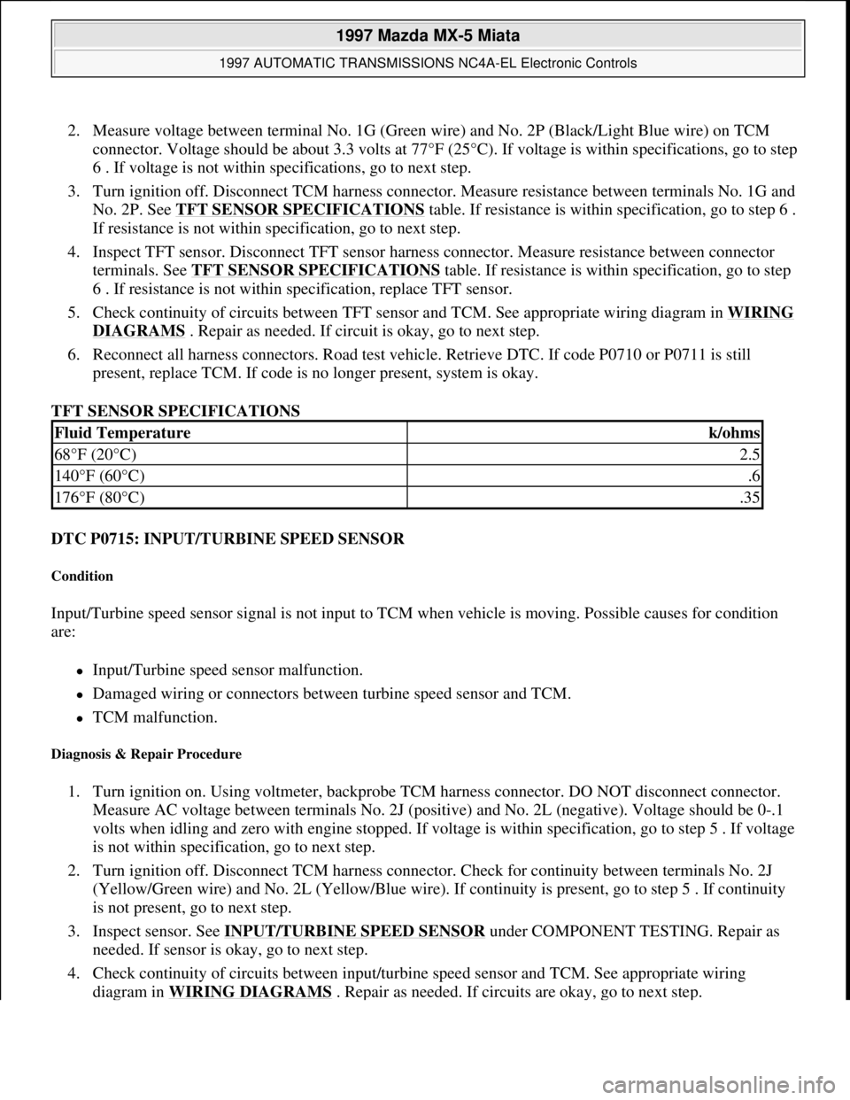
3. Turn ignition off. Disconnect TCM harness connector. Measure resistance between terminals No. 1G and
No. 2P. See TFT SENSOR SPECIFICATIONS
table. If resistance is within specification, go to step 6 .
If resistance is not within specification, go to next step.
4. Inspect TFT sensor. Disconnect TFT sensor harness connector. Measure resistance between connector
terminals. See TFT SENSOR SPECIFICATIONS
table. If resistance is within specification, go to step
6 . If resistance is not within specification, replace TFT sensor.
5. Check continuity of circuits between TFT sensor and TCM. See appropriate wiring diagram in WIRING
DIAGRAMS . Repair as needed. If circuit is okay, go to next step.
6. Reconnect all harness connectors. Road test vehicle. Retrieve DTC. If code P0710 or P0711 is still
present, replace TCM. If code is no longer present, system is okay.
TFT SENSOR SPECIFICATIONS
DTC P0715: INPUT/TURBINE SPEED SENSOR
Condition
Input/Turbine speed sensor signal is not input to TCM when vehicle is moving. Possible causes for condition
are:
Input/Turbine speed sensor malfunction.
Damaged wiring or connectors between turbine speed sensor and TCM.
TCM malfunction.
Diagnosis & Repair Procedure
1. Turn ignition on. Using voltmeter, backprobe TCM harness connector. DO NOT disconnect connector.
Measure AC voltage between terminals No. 2J (positive) and No. 2L (negative). Voltage should be 0-.1
volts when idling and zero with engine stopped. If voltage is within specification, go to step 5 . If voltage
is not within specification, go to next step.
2. Turn ignition off. Disconnect TCM harness connector. Check for continuity between terminals No. 2J
(Yellow/Green wire) and No. 2L (Yellow/Blue wire). If continuity is present, go to step 5 . If continuity
is not present, go to next step.
3. Inspect sensor. See INPUT/TURBINE SPEED SENSOR
under COMPONENT TESTING. Repair as
needed. If sensor is okay, go to next step.
4. Check continuity of circuits between input/turbine speed sensor and TCM. See appropriate wiring
dia
gram in WIRING DIAGRAMS . Repair as needed. If circuits are okay, go to next step.
Fluid Temperaturek/ohms
68°F (20°C)2.5
140°F (60°C).6
176°F (80°C).35
1997 Mazda MX-5 Miata
1997 AUTOMATIC TRANSMISSIONS NC4A-EL Electronic Controls
Microsoft
Sunday, July 05, 2009 1:35:04 PMPage 11 © 2005 Mitchell Repair Information Company, LLC.
Page 60 of 514
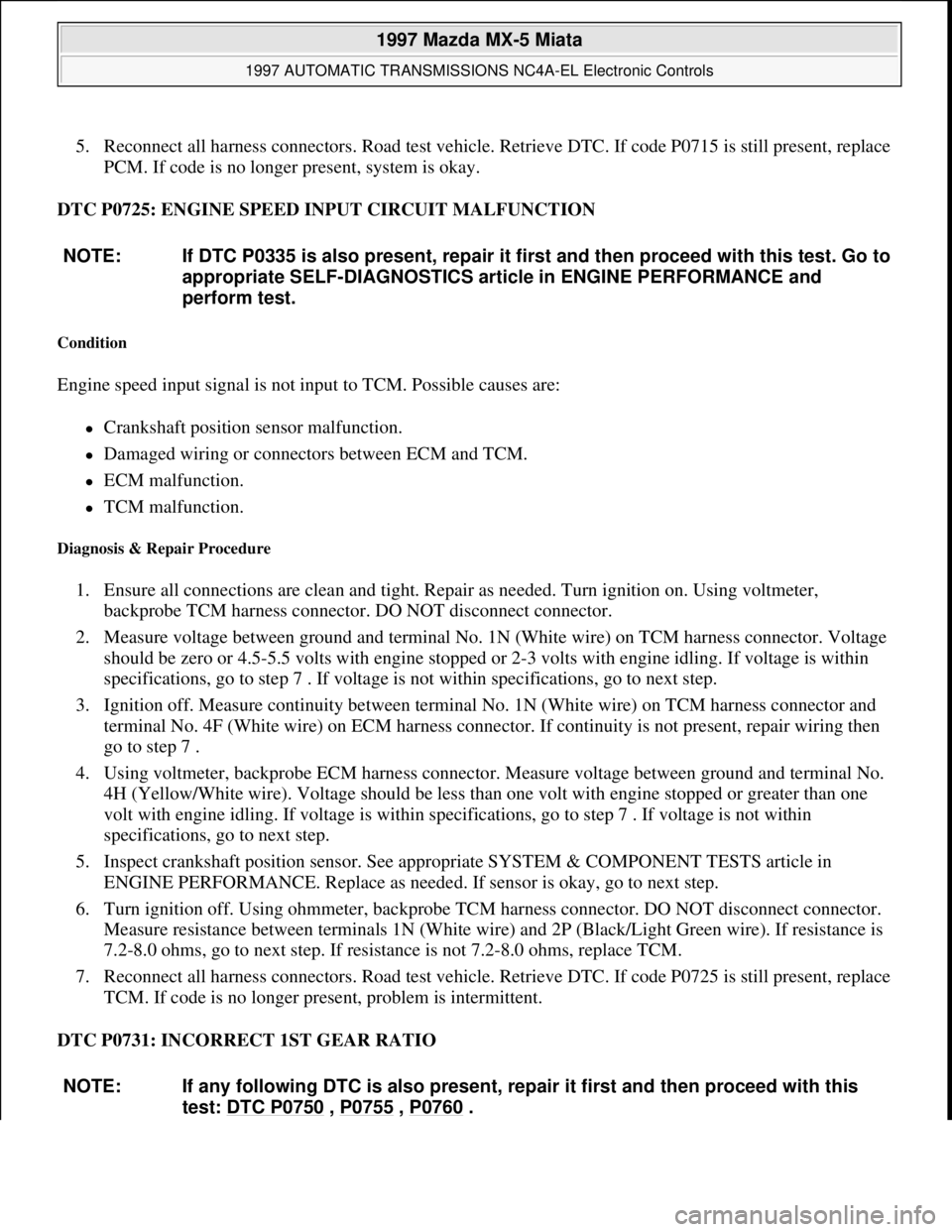
5. Reconnect all harness connectors. Road test vehicle. Retrieve DTC. If code P0715 is still present, replace
PCM. If code is no longer present, system is okay.
DTC P0725: ENGINE SPEED INPUT CIRCUIT MALFUNCTION
Condition
Engine speed input signal is not input to TCM. Possible causes are:
Crankshaft position sensor malfunction.
Damaged wiring or connectors between ECM and TCM.
ECM malfunction.
TCM malfunction.
Diagnosis & Repair Procedure
1. Ensure all connections are clean and tight. Repair as needed. Turn ignition on. Using voltmeter,
backprobe TCM harness connector. DO NOT disconnect connector.
2. Measure voltage between ground and terminal No. 1N (White wire) on TCM harness connector. Voltage
should be zero or 4.5-5.5 volts with engine stopped or 2-3 volts with engine idling. If voltage is within
specifications, go to step 7 . If voltage is not within specifications, go to next step.
3. Ignition off. Measure continuity between terminal No. 1N (White wire) on TCM harness connector and
terminal No. 4F (White wire) on ECM harness connector. If continuity is not present, repair wiring then
go to step 7 .
4. Using voltmeter, backprobe ECM harness connector. Measure voltage between ground and terminal No.
4H (Yellow/White wire). Voltage should be less than one volt with engine stopped or greater than one
volt with engine idling. If voltage is within specifications, go to step 7 . If voltage is not within
specifications, go to next step.
5. Inspect crankshaft position sensor. See appropriate SYSTEM & COMPONENT TESTS article in
ENGINE PERFORMANCE. Replace as needed. If sensor is okay, go to next step.
6. Turn ignition off. Using ohmmeter, backprobe TCM harness connector. DO NOT disconnect connector.
Measure resistance between terminals 1N (White wire) and 2P (Black/Light Green wire). If resistance is
7.2-8.0 ohms, go to next step. If resistance is not 7.2-8.0 ohms, replace TCM.
7. Reconnect all harness connectors. Road test vehicle. Retrieve DTC. If code P0725 is still present, replace
TCM. If code is no longer present, problem is intermittent.
DTC P0731: INCORRECT 1ST GEAR RATIO NOTE: If DTC P0335 is also present, repair it first and then proceed with this test. Go to
appropriate SELF-DIAGNOSTICS article in ENGINE PERFORMANCE and
perform test.
NOTE: If any following DTC is also present, repair it first and then proceed with this
test: DTC P0750
, P0755 , P0760 .
1997 Mazda MX-5 Miata
1997 AUTOMATIC TRANSMISSIONS NC4A-EL Electronic Controls
Microsoft
Sunday, July 05, 2009 1:35:04 PMPage 12 © 2005 Mitchell Repair Information Company, LLC.