MAZDA MX-5 1997 Factory Service Manual
Manufacturer: MAZDA, Model Year: 1997, Model line: MX-5, Model: MAZDA MX-5 1997Pages: 514, PDF Size: 17.89 MB
Page 41 of 514
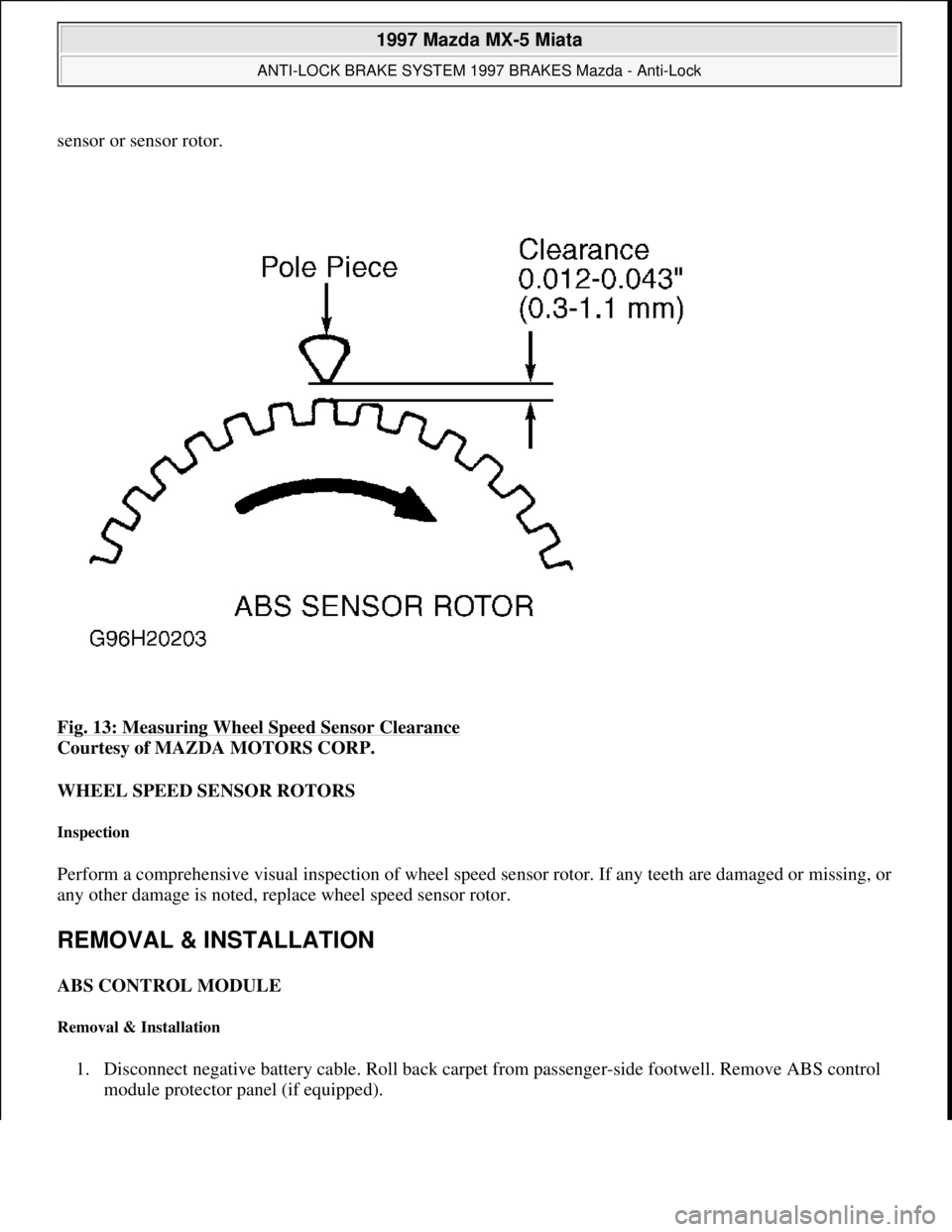
sensor or sensor rotor.
Fig. 13: Measuring Wheel Speed Sensor Clearance
Courtesy of MAZDA MOTORS CORP.
WHEEL SPEED SENSOR ROTORS
Inspection
Perform a comprehensive visual inspection of wheel speed sensor rotor. If any teeth are damaged or missing, or
any other damage is noted, replace wheel speed sensor rotor.
REMOVAL & INSTALLATION
ABS CONTROL MODULE
Removal & Installation
1. Disconnect negative battery cable. Roll back carpet from passenger-side footwell. Remove ABS control
module protector panel (if equipped).
1997 Mazda MX-5 Miata
ANTI-LOCK BRAKE SYSTEM 1997 BRAKES Mazda - Anti-Lock
Microsoft
Sunday, July 05, 2009 1:48:49 PMPage 20 © 2005 Mitchell Repair Information Company, LLC.
Page 42 of 514
2. Disconnect ABS control module electrical connector. Remove ABS control module mounting bolts/nuts.
Remove ABS control module. To install, reverse removal procedure. Tighten ABS control module
mounting bolts/nuts to 61-87 INCH lbs. (6.9-9.8 N.m).
HYDRAULIC UNIT
Removal & Installation
1. Disconnect negative battery cable. Disconnect hydraulic unit electrical connector. Using Flare Nut
Wrench (49-0259-770B), disconnect brakelines from hydraulic unit. Note location of brakelines for
installation reference. Disconnect electrical connectors. Remove hydraulic unit mounting bolts and nuts.
2. Remove hydraulic unit. To install, reverse removal procedure. Tighten mounting bolts and nuts to
specification. See TORQUE SPECIFICATIONS
. Add fluid and bleed air from system. See
BLEEDING BRAKE SYSTEM
.
FRONT WHEEL SPEED SENSOR ROTOR
Removal
Raise and support vehicle. Remove front wheel assemblies. Remove brake caliper and wire aside. Remove
rotor. Remove grease cap and wheel bearing lock nut. Remove wheel hub. Using Puller (49-0839-425C) and
Attachment (49-F027-007), remove wheel speed sensor rotor from hub.
Installation
To install, reverse removal procedure. Tighten bolts and nuts to specification. See TORQUE
SPECIFICATIONS .
REAR WHEEL SPEED SENSOR ROTOR
Removal
Raise and support vehicle. Remove rear wheel assemblies. Remove brake caliper and wire aside. Remove wheel
bearing lock nut. Remove lower control arm-to-rear steering knuckle bolt and nut. Remove drive axle. DO NOT
disassemble drive axle assembly to remove sensor rotor. Replace drive axle assembly.
Installation
To install, reverse removal procedure. Tighten bolts and nuts to specification. See TORQUE
SPECIFICATIONS .
WHEEL SPEED SENSOR
Removal & Installation
Raise and support vehicle. Remove wheel assemblies. Disconnect wheel speed sensor electrical connector.
Remove wheel speed sensor mounting bolt. Remove wheel speed sensor from vehicle. To install, reverse
1997 Mazda MX-5 Miata
ANTI-LOCK BRAKE SYSTEM 1997 BRAKES Mazda - Anti-Lock
Microsoft
Sunday, July 05, 2009 1:48:49 PMPage 21 © 2005 Mitchell Repair Information Company, LLC.
Page 43 of 514
removal procedure. Tighten mounting bolt to specification. See TORQUE SPECIFICATIONS.
VALVE & MOTOR RELAYS
Removal & Installation
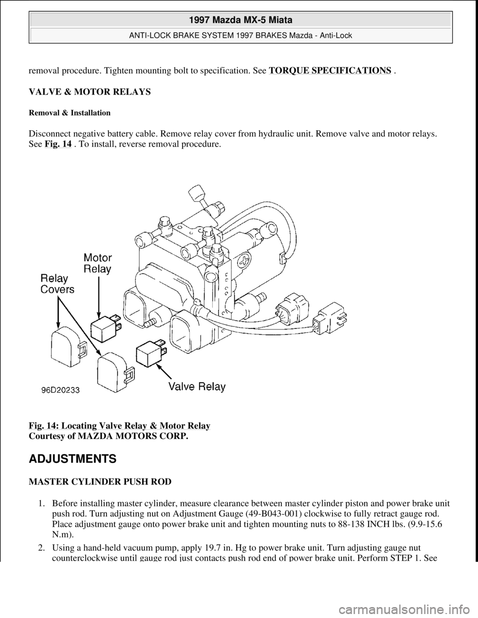
Disconnect negative battery cable. Remove relay cover from hydraulic unit. Remove valve and motor relays.
See Fig. 14
. To install, reverse removal procedure.
Fig. 14: Locating Valve Relay & Motor Relay
Courtesy of MAZDA MOTORS CORP.
ADJUSTMENTS
MASTER CYLINDER PUSH ROD
1. Before installing master cylinder, measure clearance between master cylinder piston and power brake unit
push rod. Turn adjusting nut on Adjustment Gauge (49-B043-001) clockwise to fully retract gauge rod.
Place adjustment gauge onto power brake unit and tighten mounting nuts to 88-138 INCH lbs. (9.9-15.6
N.m).
2. Using a hand-held vacuum pump, apply 19.7 in. Hg to power brake unit. Turn adjusting gauge nut
counterclockwise until
gauge rod just contacts push rod end of power brake unit. Perform STEP 1. See
1997 Mazda MX-5 Miata
ANTI-LOCK BRAKE SYSTEM 1997 BRAKES Mazda - Anti-Lock
Microsoft
Sunday, July 05, 2009 1:48:49 PMPage 22 © 2005 Mitchell Repair Information Company, LLC.
Page 44 of 514
Fig. 15 .
3. Lightly push on end of adjusting gauge rod to ensure it is properly seated. Verify no gap exists between
adjusting nut and adjusting gauge body. Remove adjusting gauge from power brake unit without
disturbing adjusting nut. Place adjusting gauge on master cylinder.
4. Lightly push on end of adjusting gauge rod to ensure gauge rod is bottomed in master cylinder piston.
Ensure no clearance exists between adjusting gauge body and adjusting nut (clearance "B") or between
body and master cylinder (clearance "C"). Perform STEP 2. See Fig. 15
.
5. If clearance "B" exists, push rod is too short. If clearance "C" exists, push rod is too long. To adjust
clearance "B", go to next step. To adjust clearance "C", go to step 8).
6. To adjust clearance "B", lightly push on end of adjusting gauge rod. Using a feeler gauge, measure
clearance between adjusting nut and adjusting gauge. Perform STEP 3. See Fig. 15
.
7. Using Push Rod Adjuster (49-B043-004) and Adapter (49-B043-003), turn push rod nut to lengthen
power brake booster push rod an amount equal to amount measured at clearance "B" in step 6). Perform
STEP 4. See Fig. 15
.
8. To adjust clearance "C", measure and record adjusting gauge rod height D1. Perfrom STEP 5. See Fig.
15 . Turn adjusting nut until adjusting gauge body sits squarely on master cylinder.
9. Turn adjusting nut only enough for body to touch adjusting gauge. Measure and record adjusting gauge
height D2 of adjusting gauge rod. Perform STEP 6. See Fig. 15
. Subtract D1 from D2 measurement.
10. Using push rod adjuster and adapter, turn push rod nut to shorten power brake booster push rod an
amount equal to difference between hei
ght D1 and D2. Perform STEP 4. See Fig. 15 . NOTE: When lightly pushing on end of adjusting gauge rod in step 4), only use
enough pressure to bottom rod in piston. Too much pressure may cause a
false reading.
NOTE: Push rod threads are specially designed so bolt becomes harder to turn
past a certain point to prevent loosening of bolt. Turn bolt only within this
range.
1997 Mazda MX-5 Miata
ANTI-LOCK BRAKE SYSTEM 1997 BRAKES Mazda - Anti-Lock
Microsoft
Sunday, July 05, 2009 1:48:49 PMPage 23 © 2005 Mitchell Repair Information Company, LLC.
Page 45 of 514
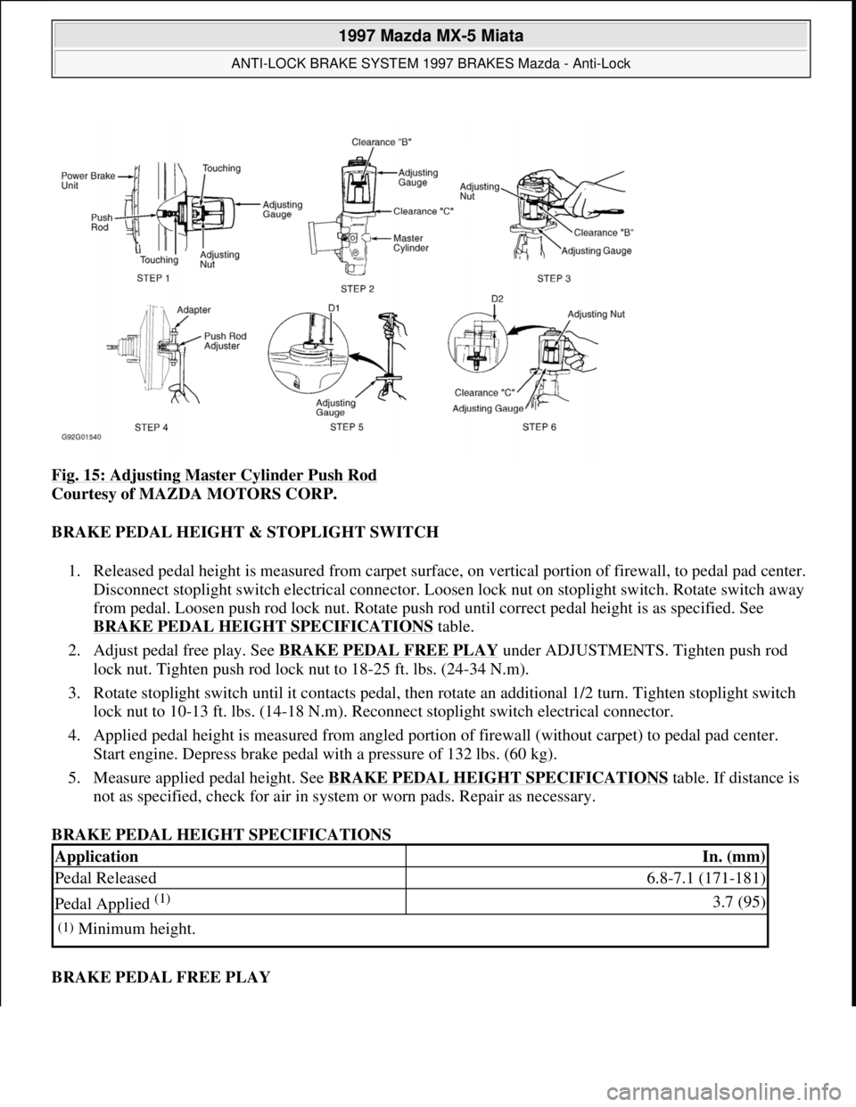
Fig. 15: Adjusting Master Cylinder Push Rod
Courtesy of MAZDA MOTORS CORP.
BRAKE PEDAL HEIGHT & STOPLIGHT SWITCH
1. Released pedal height is measured from carpet surface, on vertical portion of firewall, to pedal pad center.
Disconnect stoplight switch electrical connector. Loosen lock nut on stoplight switch. Rotate switch away
from pedal. Loosen push rod lock nut. Rotate push rod until correct pedal height is as specified. See
BRAKE PEDAL HEIGHT SPECIFICATIONS
table.
2. Adjust pedal free play. See BRAKE PEDAL FREE PLAY
under ADJUSTMENTS. Tighten push rod
lock nut. Tighten push rod lock nut to 18-25 ft. lbs. (24-34 N.m).
3. Rotate stoplight switch until it contacts pedal, then rotate an additional 1/2 turn. Tighten stoplight switch
lock nut to 10-13 ft. lbs. (14-18 N.m). Reconnect stoplight switch electrical connector.
4. Applied pedal height is measured from angled portion of firewall (without carpet) to pedal pad center.
Start engine. Depress brake pedal with a pressure of 132 lbs. (60 kg).
5. Measure applied pedal height. See BRAKE PEDAL HEIGHT SPECIFICATIONS
table. If distance is
not as specified, check for air in system or worn pads. Repair as necessary.
BRAKE PEDAL HEIGHT SPECIFICATIONS
BRAKE PEDAL FREE PLAY
ApplicationIn. (mm)
Pedal Released6.8-7.1 (171-181)
Pedal Applied (1) 3.7 (95)
(1)Minimum height.
1997 Mazda MX-5 Miata
ANTI-LOCK BRAKE SYSTEM 1997 BRAKES Mazda - Anti-Lock
Microsoft
Sunday, July 05, 2009 1:48:49 PMPage 24 © 2005 Mitchell Repair Information Company, LLC.
Page 46 of 514
With engine off, depress pedal a few times to eliminate vacuum. Depress brake pedal by hand and check pedal
free play. See BRAKE PEDAL FREE PLAY SPECIFICATIONS
table. Adjust play by loosening push rod
lock nut. Turn push rod until correct free play is obtained. Tighten push rod lock nut to 18-25 ft. lbs. (24-34
N.m).
BRAKE PEDAL FREE PLAY SPECIFICATIONS
PARKING/EMERGENCY BRAKE
1. Depress brake pedal several times. Pull parking brake lever with a force of 44 lbs. (20 kg). If stroke is 7-9
notches, parking brake is properly adjusted. If stroke is not 7-9 notches, raise and support rear of vehicle.
Release parking brake lever.
2. Rotate cable adjusting nut at lever end of cable, located under console cover, until stroke is within
specification. Ensure rear brakes do not drag. Ensure parking brake warning light illuminates when brake
lever is pulled one notch.
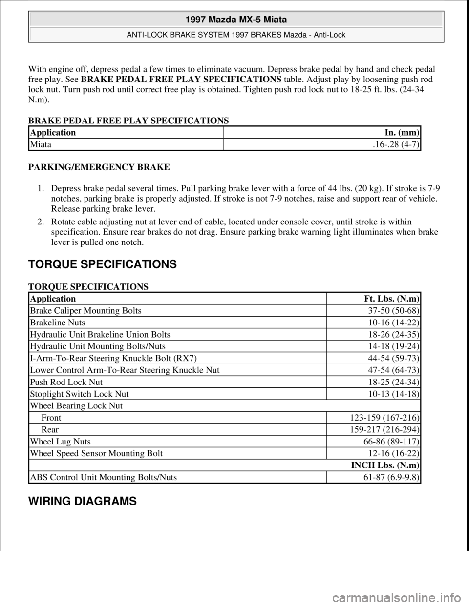
TORQUE SPECIFICATIONS
TORQUE SPECIFICATIONS
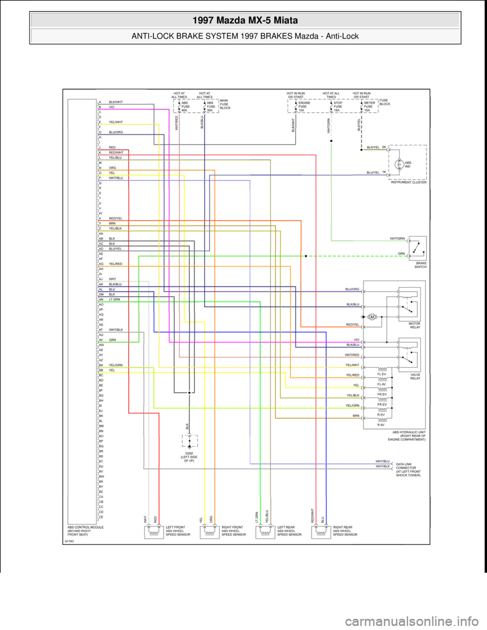
WIRING DIAGRAMS
ApplicationIn. (mm)
Miata.16-.28 (4-7)
ApplicationFt. Lbs. (N.m)
Brake Caliper Mounting Bolts37-50 (50-68)
Brakeline Nuts10-16 (14-22)
Hydraulic Unit Brakeline Union Bolts18-26 (24-35)
Hydraulic Unit Mounting Bolts/Nuts14-18 (19-24)
I-Arm-To-Rear Steering Knuckle Bolt (RX7)44-54 (59-73)
Lower Control Arm-To-Rear Steering Knuckle Nut47-54 (64-73)
Push Rod Lock Nut18-25 (24-34)
Stoplight Switch Lock Nut10-13 (14-18)
Wheel Bearing Lock Nut
Front123-159 (167-216)
Rear159-217 (216-294)
Wheel Lug Nuts66-86 (89-117)
Wheel Speed Sensor Mounting Bolt12-16 (16-22)
INCH Lbs. (N.m)
ABS Control Unit Mounting Bolts/Nuts61-87 (6.9-9.8)
1997 Mazda MX-5 Miata
ANTI-LOCK BRAKE SYSTEM 1997 BRAKES Mazda - Anti-Lock
Microsoft
Sunday, July 05, 2009 1:48:49 PMPage 25 © 2005 Mitchell Repair Information Company, LLC.
Page 47 of 514
1997 Mazda MX-5 Miata
ANTI-LOCK BRAKE SYSTEM 1997 BRAKES Mazda - Anti-Lock
Microsoft
Sunday, July 05, 2009 1:48:49 PMPage 26 © 2005 Mitchell Repair Information Company, LLC.
Page 48 of 514

Fig. 16: Anti-Lock Brake System (ABS) Wiring Diagram (1997 Miata)
1997 Mazda MX-5 Miata
ANTI-LOCK BRAKE SYSTEM 1997 BRAKES Mazda - Anti-Lock
Microsoft
Sunday, July 05, 2009 1:48:49 PMPage 27 © 2005 Mitchell Repair Information Company, LLC.
Page 49 of 514
1997 AUTOMATIC TRANSMISSIONS
NC4A-EL Electronic Controls
APPLICATION
TRANSMISSION APPLICATION
DESCRIPTION
The NC4A-EL series is a 4-speed electronically controlled automatic transmission. Five solenoids attached to
valve body control shift changes. Solenoids are controlled by the Transmission Control Module (TCM).
The TCM receives information from various input devices. The TCM uses this information to control following
solenoids:
Shift solenoids for transmission shifting.
Torque Converter Clutch (TCC) solenoid for torque converter clutch lock-up.
3-2 control solenoid for downshift timing control.
A HOLD switch is mounted on the shift lever. HOLD function may be activated in "D", "S" or "L" gears by
pressing HOLD button. In "L" and "S" positions, vehicle is held in selected gear and no upshift or downshift
takes place. This function is used for driving up steep inclines or for engine braking assistance when descending
steep grades. If activated in "D" position a 1-2 and 2-3 upshift is permitted when starting from a stop, but after
the 2-3 upshift the vehicle is locked in "D" until it comes to a complete stop. The 1-2 and 2-3 upshift pattern is
changed to a "short shift" specification. This function is used for starting off or driving on slippery surfaces.
Pushin
g HOLD button again deactivates system.
VehicleTransmission Model
MiataNC4A-EL
CAUTION: Vehicle is equipped with Supplemental Restraint System (SRS). When
servicing vehicle, use care to avoid accidental air bag deployment. SRS-
related components are located in steering column, center console and
instrument panel. DO NOT use electrical test equipment on these circuits.
If necessary, deactivate SRS before servicing components. See AIR BAG
DEACTIVATION PROCEDURES article in GENERAL INFORMATION.
CAUTION: Disconnecting battery on models equipped with anti-theft radio require
canceling of anti-theft operation. See appropriate AUTOMATIC
TRANSMISSION SERVICING article in TRANSMISSION SERVICING. Refer
to vehicle owner's manual to identify radio type.
NOTE: Torque Converter Clutch (TCC) solenoid is also known as lock-up solenoid,
TCC lock-up or 4th gear solenoid.
1997 Mazda MX-5 Miata
1997 AUTOMATIC TRANSMISSIONS NC4A-EL Electronic Controls
1997 Mazda MX-5 Miata
1997 AUTOMATIC TRANSMISSIONS NC4A-EL Electronic Controls
Microsoft
Sunday, July 05, 2009 1:35:03 PMPage 1 © 2005 Mitchell Repair Information Company, LLC.
Microsoft
Sunday, July 05, 2009 1:35:38 PMPage 1 © 2005 Mitchell Repair Information Company, LLC.
Page 50 of 514
OPERATION
TCM
TCM receives information from various input devices and uses this information to control solenoids on
transmission valve body for transmission shifting and torque converter clutch engagement.
TCM automatically switches from NORMAL mode to POWER mode corresponding to driving condition in
"D" range. Upshifts and downshifts are performed at a higher speed in POWER mode than in NORMAL mode.
TCM contains a self-diagnostic system, which will store Diagnostic Trouble Codes (DTC) if a failure or
problem exists in electronic control system. DTC can be retrieved to determine problem area. See SELF-
DIAGNOSTIC SYSTEM . TCM is located under left side of instrument panel, above fuse block.
TCM INPUT DEVICES & SIGNALS
4th Gear Inhibit Signal
Signal is input to TCM when cruise control is on. Signal detects when difference between target speed and
actual speed exceeds specification.
HOLD Switch
HOLD switch delivers input to TCM to indicate gears preferred by operator. Switch is located on shift lever
handle. HOLD switch is canceled when ignition switch is turned off.
Input/Turbine Speed Sensor
Sensor is a magnetic pick-up type pulse generator that monitors input shaft speed. AC waveform is input to
TCM by output speed sensor. Sensor is located on front of transmission, back of converter housing.
Throttle Position (TP) Sensor
TP sensor delivers an input signal to TCM indicating throttle valve position (opening). TP sensor is located on
side of throttle body.
Transmission Range Switch
Transmission range switch delivers an input signal to TCM indicating shift lever position. Switch is located on
side of transmission.
Transmission Fluid Temperature (TFT) Sensor
TFT sensor is threaded into cooler line banjo mounting on side of transmission case. Sensor sends signal to
TCM indicating fluid temperature.
Vehicle Speed Sensor
1997 Mazda MX-5 Miata
1997 AUTOMATIC TRANSMISSIONS NC4A-EL Electronic Controls
Microsoft
Sunday, July 05, 2009 1:35:03 PMPage 2 © 2005 Mitchell Repair Information Company, LLC.