MAZDA MX-5 1997 Factory Manual Online
Manufacturer: MAZDA, Model Year: 1997,
Model line: MX-5,
Model: MAZDA MX-5 1997
Pages: 514, PDF Size: 17.89 MB
MAZDA MX-5 1997 Factory Manual Online
MX-5 1997
MAZDA
MAZDA
https://www.carmanualsonline.info/img/28/57070/w960_57070-0.png
MAZDA MX-5 1997 Factory Manual Online
Trending: dimensions, transmission, radiator, height, park assist, cruise control, wheel alignment
Page 81 of 514
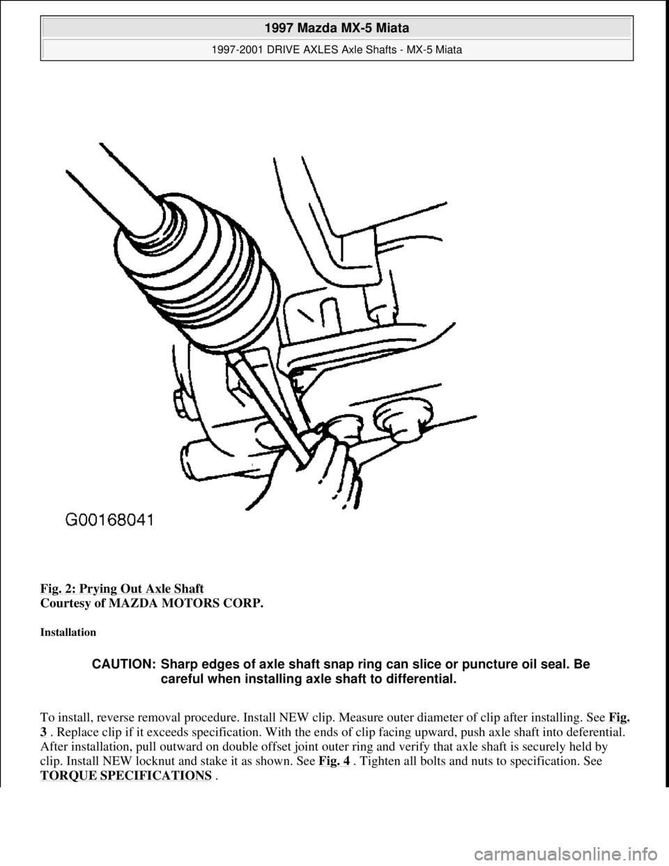
Fig. 2: Prying Out Axle Shaft
Courtesy of MAZDA MOTORS CORP.
Installation
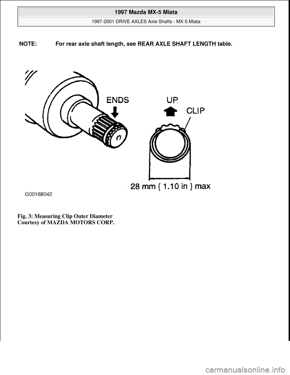
To install, reverse removal procedure. Install NEW clip. Measure outer diameter of clip after installing. See Fig.
3 . Replace clip if it exceeds specification. With the ends of clip facing upward, push axle shaft into deferential.
After installation, pull outward on double offset joint outer ring and verify that axle shaft is securely held by
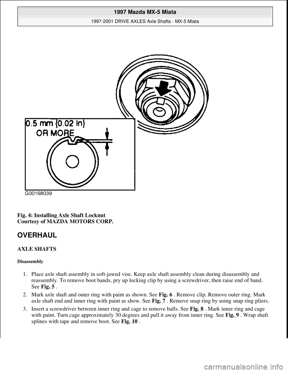
clip. Install NEW locknut and stake it as shown. See Fig. 4
. Tighten all bolts and nuts to specification. See
TORQUE SPECIFICATIONS
.
CAUTION: Sharp edges of axle shaft snap ring can slice or puncture oil seal. Be
careful when installing axle shaft to differential.
1997 Mazda MX-5 Miata
1997-2001 DRIVE AXLES Axle Shafts - MX-5 Miata
Microsoft
Sunday, July 05, 2009 1:51:37 PMPage 3 © 2005 Mitchell Repair Information Company, LLC.
Page 82 of 514
Fig. 3: Measuring Clip Outer Diameter
Courtesy of MAZDA MOTORS CORP. NOTE: For rear axle shaft length, see REAR AXLE SHAFT LENGTH
table.
1997 Mazda MX-5 Miata
1997-2001 DRIVE AXLES Axle Shafts - MX-5 Miata
Microsoft
Sunday, July 05, 2009 1:51:37 PMPage 4 © 2005 Mitchell Repair Information Company, LLC.
Page 83 of 514
Fig. 4: Installing Axle Shaft Locknut
Courtesy of MAZDA MOTORS CORP.
OVERHAUL
AXLE SHAFTS
Disassembly
1. Place axle shaft assembly in soft-jawed vise. Keep axle shaft assembly clean during disassembly and
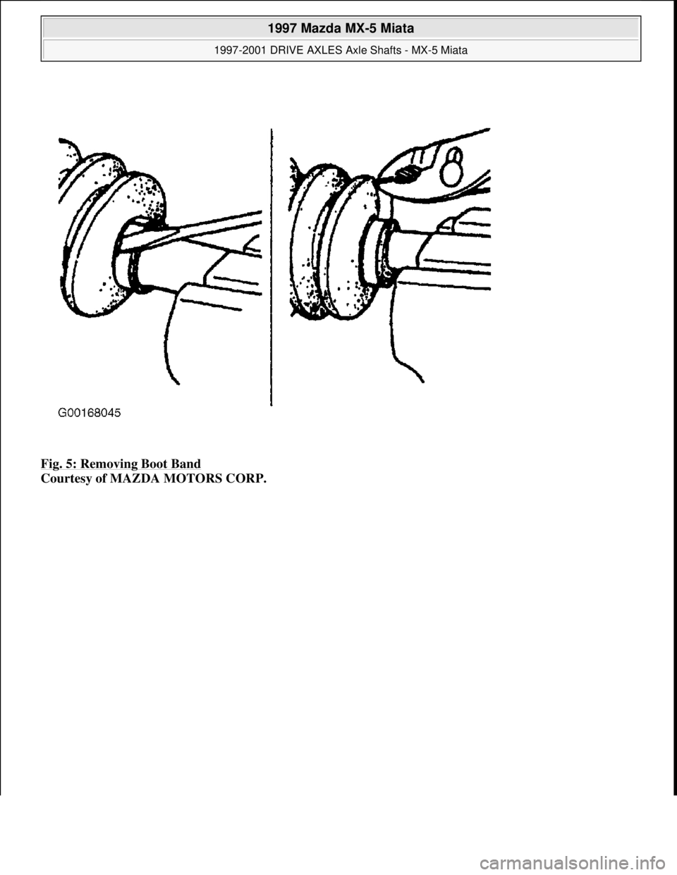
reassembly. To remove boot bands, pry up locking clip by using a screwdriver, then raise end of band.
See Fig. 5
.
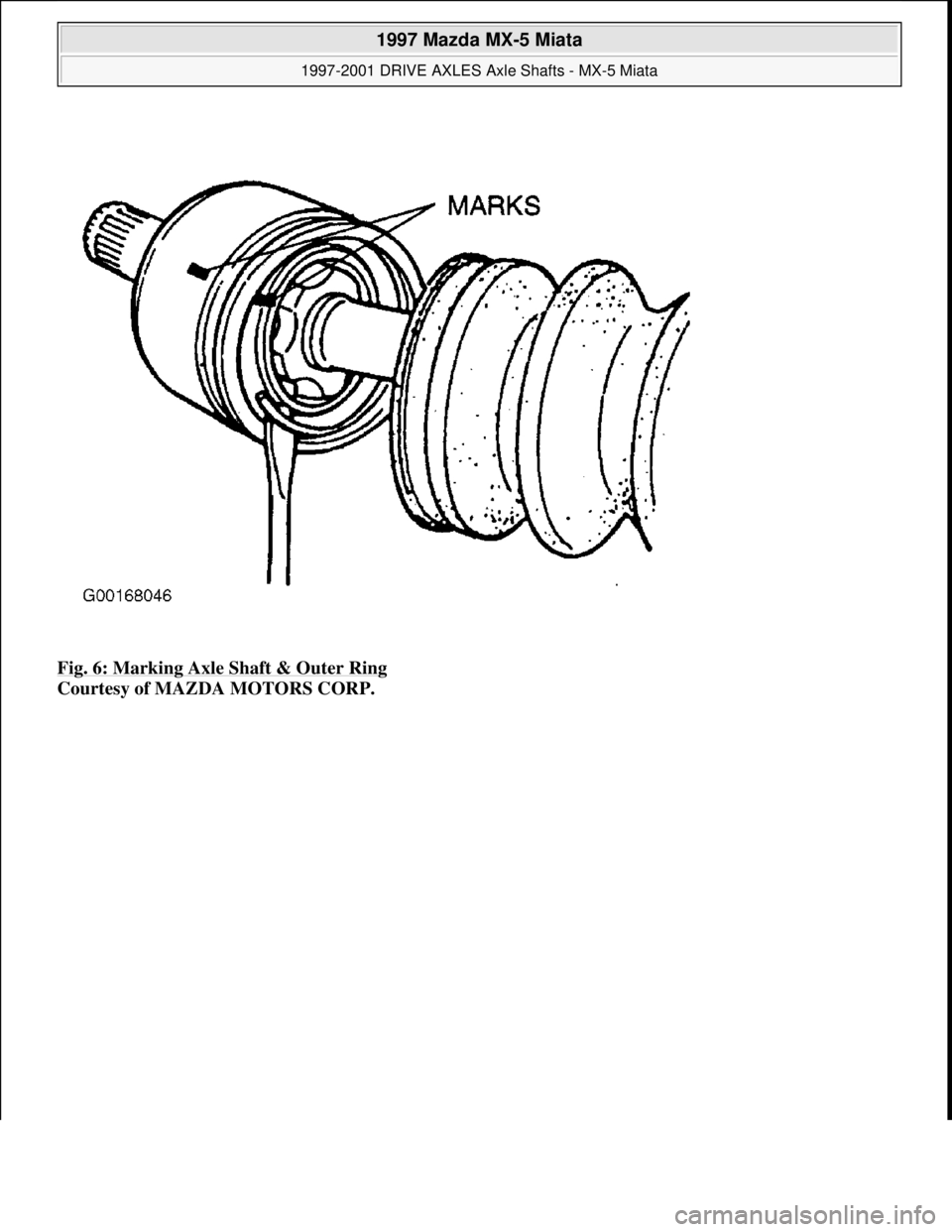
2. Mark axle shaft and outer ring with paint as shown. See Fig. 6
. Remove clip. Remove outer ring. Mark
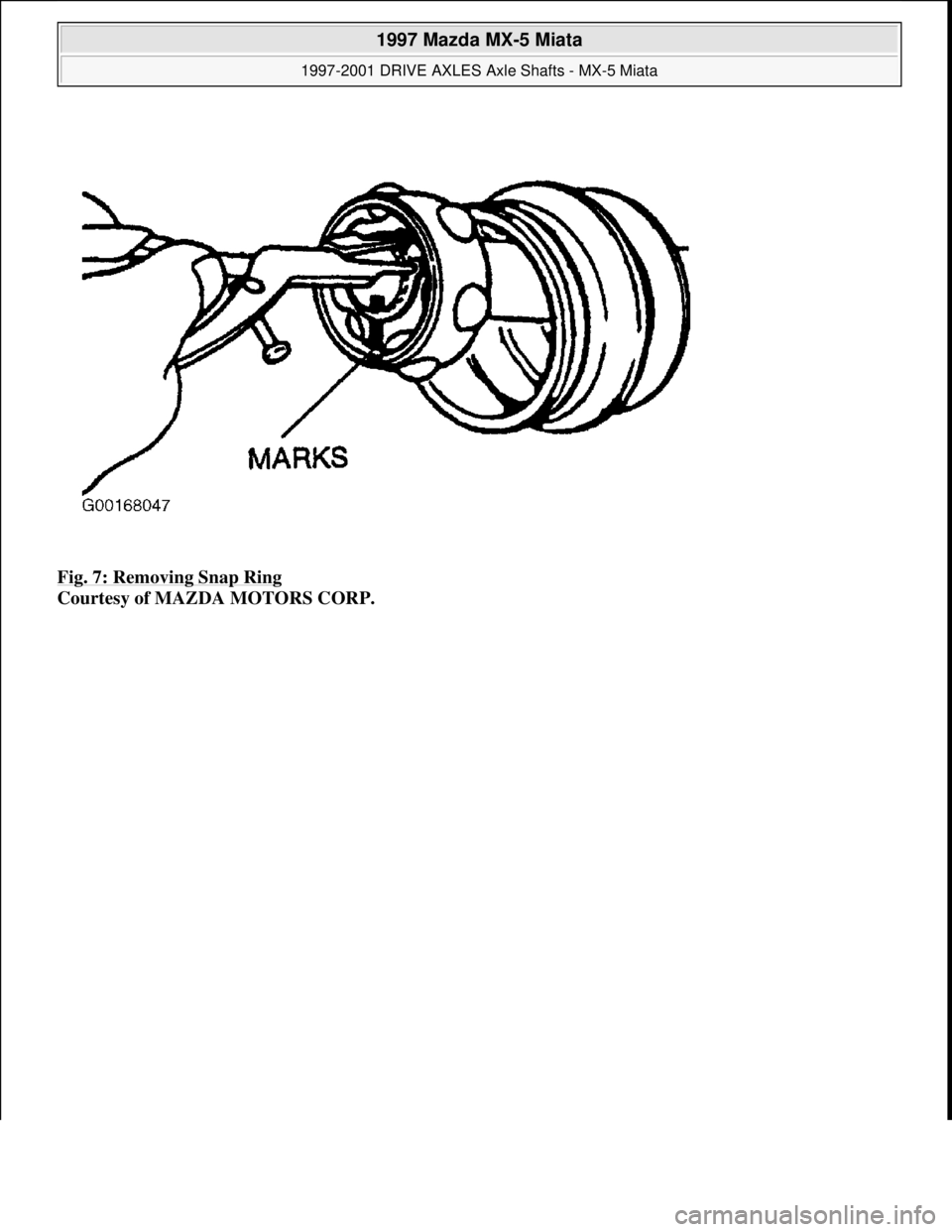
axle shaft end and inner ring with paint as show. See Fig. 7
. Remove snap ring by using snap ring pliers.
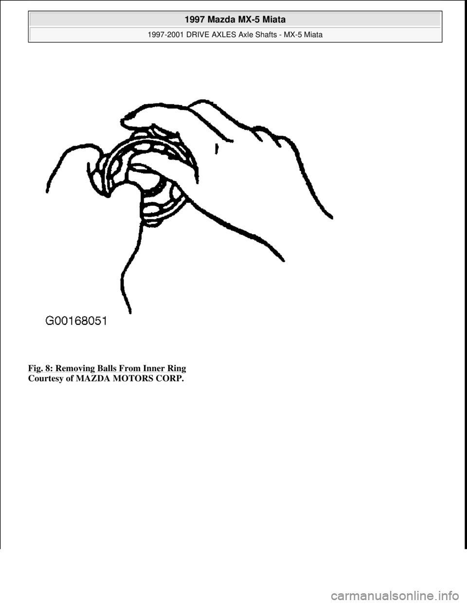
3. Insert a screwdriver between inner ring and cage to remove balls. See Fig. 8
. Mark inner ring and cage
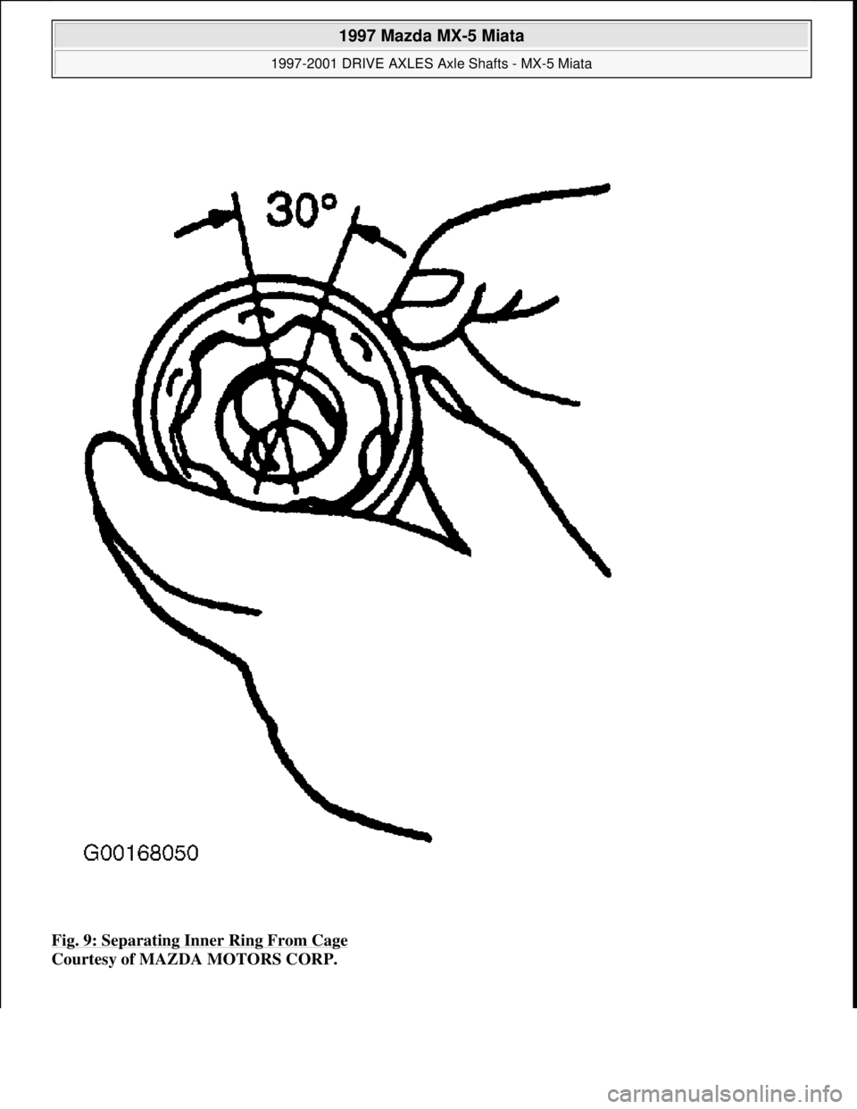
with paint. Turn cage approximately 30 degrees and pull it away from inner ring. See Fig. 9
. Wrap shaft
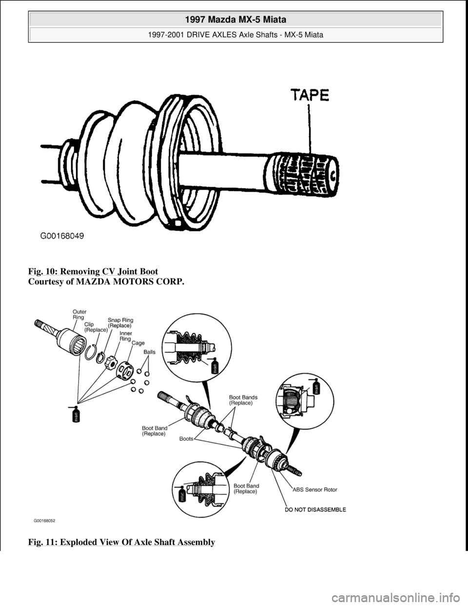
splines with tape and remove boot. See Fig. 10
.
1997 Mazda MX-5 Miata
1997-2001 DRIVE AXLES Axle Shafts - MX-5 Miata
Microsoft
Sunday, July 05, 2009 1:51:37 PMPage 5 © 2005 Mitchell Repair Information Company, LLC.
Page 84 of 514
Fig. 5: Removing Boot Band
Courtesy of MAZDA MOTORS CORP.
1997 Mazda MX-5 Miata
1997-2001 DRIVE AXLES Axle Shafts - MX-5 Miata
Microsoft
Sunday, July 05, 2009 1:51:37 PMPage 6 © 2005 Mitchell Repair Information Company, LLC.
Page 85 of 514
Fig. 6: Marking Axle Shaft & Outer Ring
Courtesy of MAZDA MOTORS CORP.
1997 Mazda MX-5 Miata
1997-2001 DRIVE AXLES Axle Shafts - MX-5 Miata
Microsoft
Sunday, July 05, 2009 1:51:37 PMPage 7 © 2005 Mitchell Repair Information Company, LLC.
Page 86 of 514
Fig. 7: Removing Snap Ring
Courtesy of MAZDA MOTORS CORP.
1997 Mazda MX-5 Miata
1997-2001 DRIVE AXLES Axle Shafts - MX-5 Miata
Microsoft
Sunday, July 05, 2009 1:51:37 PMPage 8 © 2005 Mitchell Repair Information Company, LLC.
Page 87 of 514
Fig. 8: Removing Balls From Inner Ring
Courtesy of MAZDA MOTORS CORP.
1997 Mazda MX-5 Miata
1997-2001 DRIVE AXLES Axle Shafts - MX-5 Miata
Microsoft
Sunday, July 05, 2009 1:51:37 PMPage 9 © 2005 Mitchell Repair Information Company, LLC.
Page 88 of 514
Fig. 9: Separating Inner Ring From Cage
Courtesy of MAZDA MOTORS CORP.
1997 Mazda MX-5 Miata
1997-2001 DRIVE AXLES Axle Shafts - MX-5 Miata
Microsoft
Sunday, July 05, 2009 1:51:37 PMPage 10 © 2005 Mitchell Repair Information Company, LLC.
Page 89 of 514
Fig. 10: Removing CV Joint Boot
Courtesy of MAZDA MOTORS CORP.
Fig. 11: Exploded View Of Axle Shaft Assembly
1997 Mazda MX-5 Miata
1997-2001 DRIVE AXLES Axle Shafts - MX-5 Miata
Microsoft
Sunday, July 05, 2009 1:51:37 PMPage 11 © 2005 Mitchell Repair Information Company, LLC.
Page 90 of 514
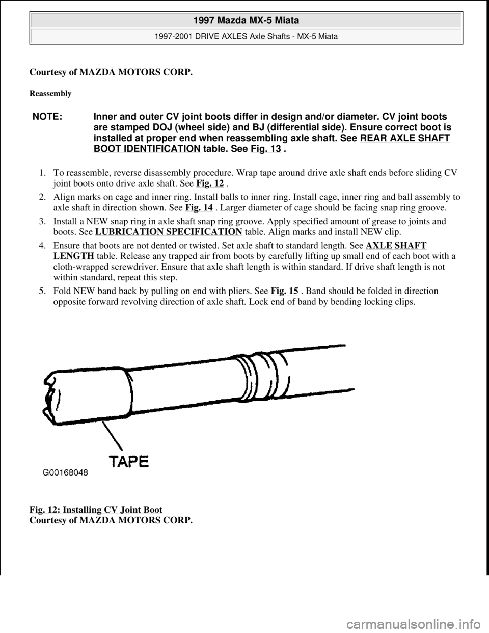
Courtesy of MAZDA MOTORS CORP.
Reassembly
1. To reassemble, reverse disassembly procedure. Wrap tape around drive axle shaft ends before sliding CV
joint boots onto drive axle shaft. See Fig. 12
.
2. Align marks on cage and inner ring. Install balls to inner ring. Install cage, inner ring and ball assembly to
axle shaft in direction shown. See Fig. 14
. Larger diameter of cage should be facing snap ring groove.
3. Install a NEW snap ring in axle shaft snap ring groove. Apply specified amount of grease to joints and
boots. See LUBRICATION SPECIFICATION
table. Align marks and install NEW clip.
4. Ensure that boots are not dented or twisted. Set axle shaft to standard length. See AXLE SHAFT
LENGTH table. Release any trapped air from boots by carefully lifting up small end of each boot with a
cloth-wrapped screwdriver. Ensure that axle shaft length is within standard. If drive shaft length is not
within standard, repeat this step.
5. Fold NEW band back by pulling on end with pliers. See Fig. 15
. Band should be folded in direction
opposite forward revolving direction of axle shaft. Lock end of band by bending locking clips.
Fig. 12: Installing CV Joint Boot
Courtesy of MAZDA MOTORS CORP. NOTE: Inner and outer CV joint boots differ in design and/or diameter. CV joint boots
are stamped DOJ (wheel side) and BJ (differential side). Ensure correct boot is
installed at proper end when reassembling axle shaft. See REAR AXLE SHAFT
BOOT IDENTIFICATION table. See Fig. 13 .
1997 Mazda MX-5 Miata
1997-2001 DRIVE AXLES Axle Shafts - MX-5 Miata
Microsoft
Sunday, July 05, 2009 1:51:37 PMPage 12 © 2005 Mitchell Repair Information Company, LLC.
Trending: service indicator, ignition, fuses, dashboard, fuel filter location, fog light, window
